@masterkenobi said:
........... I am wondering what is the black rectangle thingy next to the LEDs for.
It's a pushbutton for inclusion of new nodes.
@masterkenobi said:
........... I am wondering what is the black rectangle thingy next to the LEDs for.
It's a pushbutton for inclusion of new nodes.
Thanks, I knew about that but that is not what I was looking for. When the switch is pushed OR in the webGUI the button 'Start' is clicked on, the LED does not react. It used to blink continuously in v1.4 while in 'discovery' mode'.
Otherwise the LED's do work fine for RX and TX so I know the yellow one for inclusion does work.
In v1.4 a yellow LED was slowly blinking while in inclusion-mode; this was nice. For me this was in v1.4.1 to be exact.
Today I updated to 1.5 and not only is the (optional) switch now reversed, but the LED only blinks ones when it finishes.
The switch was for me easy to fix because I had pins for default-closed as well but the LED is a pity.
I'm running a serial gateway with a VeraLite UI7 with the updated UI7 files. Nice graphics!
Edit: typos
It just works now!
I removed the Ethernet gateway device from the UI and added the new device as per description on the webside. For a short while I had the error ComFailure but found on the forum that in advanced this must be altered from 1 to 0.
@hek
Ok, I missed that news than. Will try that one of these days because have it still laying around. I remember the serial port was there but the device disapeard in the UI.
@hek said:
You should use an Arduino Nano for the Vera gateway as it has a hard time recognising the Uno board.
http://www.mysensors.org/build/serial_gateway
and
Are you sure?
An edge is running ui7 and then a serial gateway will not work. I had one running fine on my VeraLite until I 'upgraded' it to ui7. I never got it working until I built an Ethernet gateway.
Did this with an uno with 5100 shield. Runs perfectly, still hate ui7 though...
Hi, just teaming up because I have the exact same problem.
http://forum.micasaverde.com/index.php/topic,30528.msg247112.html#msg247112
It is absolutely a software problem because this same hardware run fine with UI5.
Doesn't the UNO already has the optiboot loader standard?
See: https://github.com/Optiboot/optiboot
Thuis non-FTDI problem has been mentioned before:
http://forum.mysensors.org/topic/1024/serial-port-configuration-not-available
An uno as serial gateway?.
I think that is not supported and you should use a nano for that:
http://www.mysensors.org/build/serial_gateway
You have a sharp eye!
Have a good read at http://forum.micasaverde.com/index.php?topic=19263.15
It is all in there.
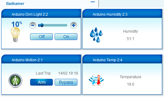
Finally a new DHT22 arrived from China and now this project is completely finished.
@NotYetRated
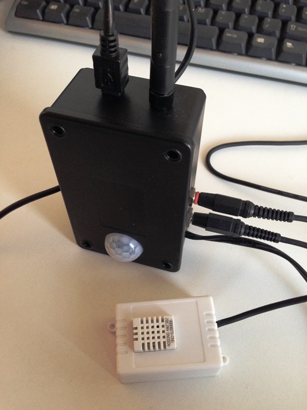
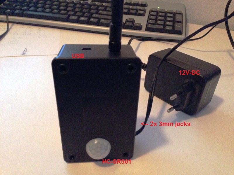
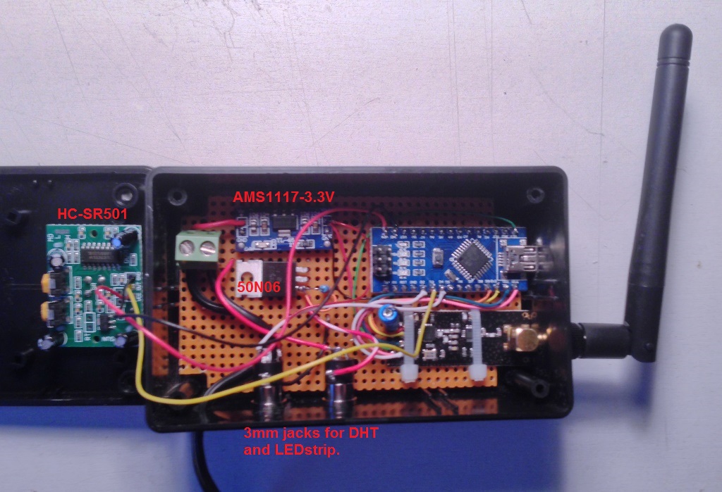
The components are:
The LEDstrip and DHT are connected via 3mm plugs and jacks.
The DHT and NRF are fed by the 3.3v regulator. The nano and FET are using the raw 12v.
The sketch:
(sorry, no working codebender account yet)
/***
 * This program is free software; you can redistribute it and/or
 * modify it under the terms of the GNU General Public License
 * version 2 as published by the Free Software Foundation.
 *
 * DESCRIPTION
 * This sketch provides a Dimmable LED Light using PWM and based Henrik Ekblad
 * <henrik.ekblad@gmail.com> Vera Arduino Sensor project.
 * Developed by Bruce Lacey, inspired by Hek's MySensor's example sketches.
 *
 * The circuit uses a MOSFET for Pulse-Wave-Modulation to dim the attached LED or LED strip.
 * The MOSFET Gate pin is connected to Arduino pin 3 (LED_PIN), the MOSFET Drain pin is connected
 * to the LED negative terminal and the MOSFET Source pin is connected to ground.
 *
 * This sketch is extensible to support more than one MOSFET/PWM dimmer per circuit.
 *
 * REVISION HISTORY
 * Version 1.0  - February 15, 2014 - Bruce Lacey
 * Version 1.1  - August 13, 2014 - Converted to 1.4 (hek)
 * Version 1.1a - August 14, 2014 - Added MotionSensor (Ed)
 * Version 1.1b - December 22, 2014 - Added DHT-Sensor (Ed)
 * Version 1.1c - December 29, 2014 - Added LED timeout (Ed)
 * Version 1.1d - Januari 4, 2015 - Updated lib to 1.4.1 (Ed)
 *
 ***/
#define SN "DimmableLED"
#define SV "1.1d"

#include <MySensor.h>
#include <SPI.h>
#include <DHT.h>

#define Motion_PIN 3           // The digital input you attached your motion sensor.  (Only 2 and 3 generates interrupt!)
#define INTERRUPT Motion_PIN-2 // Usually the interrupt = pin -2 (on uno/nano anyway)
#define LED_PIN 5              // Arduino pin attached to MOSFET Gate pin
#define DHT_PIN 4
#define FADE_DELAY 30          // Delay in ms for each percentage fade up/down (10ms = 1s full-range dim)
#define Motion_CHILD 1         // Id of the MotionSensor child
#define Dimmer_CHILD 2         // Id of the DimmableLED child
#define Hum_CHILD 3            // Id of the DHT-humidity child
#define Temp_CHILD 4           // Id of the DHT-temperature child
boolean lastMotion = false;

MySensor gw(9,10);
DHT dht;
float lastTemp;
float lastHum;
static int currentLevel = 0;       // Current dim level...
long previousMillisDHT = 0;        // stores last time DHT was updated
long previousMillisLED = 0;        // stores last time LED was updated
long intervalDHT = 60000;          // read DHT every ....
long durationLED = 1800000;        // Max 'On'-time for LED's (watchdog)
MyMessage motionMsg(Motion_CHILD, V_TRIPPED);
MyMessage dimmerMsg(Dimmer_CHILD, V_DIMMER);
MyMessage lightMsg(Dimmer_CHILD, V_LIGHT);
MyMessage humMsg(Hum_CHILD, V_HUM);
MyMessage tempMsg(Temp_CHILD, V_TEMP);

void setup()
{
  // Serial.println( SN );
  gw.begin( incomingMessage );    // Listen to dimmer-info from Vera
  dht.setup(DHT_PIN);

  // Register all sensors to gw (they will be created as child devices)
  gw.present( Motion_CHILD, S_MOTION );
  gw.present( Dimmer_CHILD, S_DIMMER );
  gw.present( Hum_CHILD, S_HUM );
  gw.present( Temp_CHILD, S_TEMP );

  gw.sendSketchInfo(SN, SV);
  // Pull the gateway's current dim level - restore light level upon sender node power-up
  gw.request( Dimmer_CHILD, V_DIMMER );
}


void loop()
{
  gw.process();

  // Read digital motion value
  boolean motion = digitalRead(Motion_PIN) == HIGH;
  if (lastMotion != motion) {
    lastMotion = motion;
    gw.send(motionMsg.set(motion ? "1" : "0" ));  // Send motion value to gw
  }

  // DHT22:
  unsigned long currentMillisDHT = millis();
  if(currentMillisDHT - previousMillisDHT > intervalDHT) {
    previousMillisDHT = currentMillisDHT;

    float temperature = dht.getTemperature();
    if (isnan(temperature)) {
      Serial.println("Failed reading temperature from DHT");
    } else if (temperature != lastTemp) {
      lastTemp = temperature;

      gw.send(tempMsg.set(temperature, 1));
      Serial.print("T: ");
      Serial.println(temperature);
    }

    float humidity = dht.getHumidity();
    if (isnan(humidity)) {
      Serial.println("Failed reading humidity from DHT");
    } else if (humidity != lastHum) {
      lastHum = humidity;
      gw.send(humMsg.set(humidity, 1));
      Serial.print("H: ");
      Serial.println(humidity);
    }
  }

  // Limit LED 'On'-time.
  unsigned long currentMillis = millis();

    if (( currentLevel > 0 ) && ((currentMillis - previousMillisLED) > durationLED)) {
      analogWrite( LED_PIN, 0 );              // Kill LED's after max 'On'-time
      gw.send(dimmerMsg.set(0));
      currentLevel=0;
    }

}


void incomingMessage(const MyMessage &message) {
  if (message.type == V_LIGHT || message.type == V_DIMMER) {

    //  Retrieve the power or dim level from the incoming request message
    int requestedLevel = atoi( message.data );

    // Adjust incoming level if this is a V_LIGHT variable update [0 == off, 1 == on]
    requestedLevel *= ( message.type == V_LIGHT ? 100 : 1 );

    // Clip incoming level to valid range of 0 to 100
    requestedLevel = requestedLevel > 100 ? 100 : requestedLevel;
    requestedLevel = requestedLevel < 0   ? 0   : requestedLevel;

    // Serial.print( "Changing level from " );
    // Serial.print( currentLevel );
    // Serial.print( " to " );
    // Serial.println( requestedLevel );

    fadeToLevel( requestedLevel );

    // Inform the gateway of the current DimmableLED's SwitchPower1 and LoadLevelStatus value...
    // gw.send(lightMsg.set(currentLevel > 0 ? 1 : 0));

    }
}

// This method provides a graceful fade up/down effect
void fadeToLevel( int toLevel ) {
  if (toLevel > 0){ previousMillisLED = millis();}
  int delta = ( toLevel - currentLevel ) < 0 ? -1 : 1;

  while ( currentLevel != toLevel ) {
    currentLevel += delta;
    analogWrite( LED_PIN, (int)(currentLevel / 100. * 255) );
    delay( FADE_DELAY );
  }
}
LEDdimmer.ino
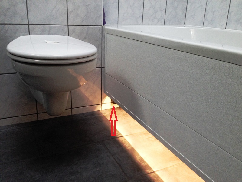
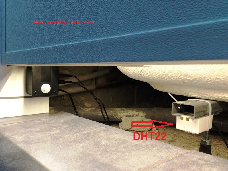
The DHT part in the sketch is not in use because I damaged the sensor by using the wrong voltage :( but this part is 'standard' code borrowed from the MySensors libraries. The project is a succes in my eyes; the box is not visable ander the bath but the motionsensor is sensitive enough to trigger everytime someone enters the room. The sensor gets untripped after 30 seconds but I have PLEG switch off the LED's 90 seconds after still being untrapped. This way I can change the timeout without opening the box. Only the watchdog part is my doing and I'm the worst coder on this forum so be warned :)
@BulldogLowell
Ok, thanks for explaining. I'm no programmer but trying to understand the code. So because there is also a sleep-periode, the earlier mentioned delay could be omitted? I do not fully understand how the motion interrupt is working but I replaced the 30 second sleep with a few lines using millis, as you implied so that the loop keeps on running to do other things.
At the moment my sensor is a working combination of a LED-dimmer with a motion-sensor and now trying to add a DHT. This stuff is fun!
Posted some photo's at http://forum.mysensors.org/topic/781/my-led-dimmer-motion-temp-hum-sensor
Nothing new but just my implementation of great examples found on this forum and made 'my own' :)
A LED-dimmer triggered with a motion-sensor and managed via PLEG on a VeraLite. The box is mounted under my bathtub as floor-lighting. PLEG takes care of the intensity depending on day- or night. The sketch has a watchdog routine for taking care of switching of might there never be an 'off' command coming in from Vera.
Question about a minor detail:
Wouldn't a motionsenser trip be missed during:
delay(dht.getMinimumSamplingPeriod()); ?
For a DHT22 this is 2 seconds... or does the interrupt still has precedence?
@hek
That is great! Thank you very much, it worked first time. I have a LED-strip with a 50N06 FET connected to 12v and a 10K pull-down on the gate. Flawless!
Well, maybe one tiny little thing: when the dimmer is at 100% and I press the minus it always goes to 80% instead of 90%.
But this is not something in the sketch but in the library.
About the part:
// hek comment: Is this really nessesary?
gw.send( dimmerMsg.set(currentLevel) );
I left that out and there is no difference at all
Edit: I tried about every markdown possibility there is to create a code-block but it doesn't work. Sorry.
@blacey
You're sketch looks really nice and I would like to use it but I started already with the 1.4 libraries. Any chance you will rewrite it for 1.4? I've had a look at it but it's to complicated for me to understand.
To be honest, I could not believe it had to do with the power. So I kept on trying several other things like changing channels. But in the end nothing really helped so I lowered to "RF24_PA_HIGH" for the GateWay. And THAT really helped :flushed:
So I must admit that the 3.3v is not up to the demand. That is weird because I use a LM1117 on a breakout board plus on additional capacitor over the 3.3v side. 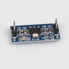
Could it the be that the Nano's 5v is not up to it to deliver enough current from it's 5v pin?
I have the GateWay on an external USB-hub with its own power-source.