Skip to content
  • MySensors
  • OpenHardware.io
  • Categories
  • Recent
  • Tags
  • Popular
Skins
  • Light
  • Brite
  • Cerulean
  • Cosmo
  • Flatly
  • Journal
  • Litera
  • Lumen
  • Lux
  • Materia
  • Minty
  • Morph
  • Pulse
  • Sandstone
  • Simplex
  • Sketchy
  • Spacelab
  • United
  • Yeti
  • Zephyr
  • Dark
  • Cyborg
  • Darkly
  • Quartz
  • Slate
  • Solar
  • Superhero
  • Vapor

  • Default (No Skin)
  • No Skin
Collapse
Brand Logo
dbemowskD

dbemowsk

@dbemowsk
About
Posts
1.4k
Topics
90
Shares
0
Groups
1
Followers
4
Following
0

Posts

Recent Best Controversial

  • What did you build today (Pictures) ?
    dbemowskD dbemowsk

    Though not fully finished, I am prototyping a new in-wall switch/scene controller with an integrated 128x64 OLED display. The design is made to fit my decora wall switch design that I had posted a while back. Here is a mock up of how I think the keypad and screen will be layed out.
    !0_1513471867393_4ef1b764-81be-48e7-9047-0493e0467626-image.png
    0_1513471973166_221268ef-db5a-4572-9929-536364bbd172-image.png

    For the screen, I am hoping to display the current room temperature and possibly the outside temp. I can also scroll messages across the screen if needed. I can also do some custom graphics and icons.

    I have tested the display connected to my uno with the Adafruit sample code and think it does a nice job. This is not my video, but it is the same sample code that I used to test it.
    https://www.youtube.com/watch?v=ldq0-IXl_GM

    I'll post more as I get further along.

    General Discussion

  • Custom icons
    dbemowskD dbemowsk

    I thought I would post a few custom icons that I made for my Domoticz setup. If anyone is interested I will post the zip files needed to add them to Domoticz.
    Garage door controller Garage door off Garage door on

    Irrigation zone sprinkler Irrigation zone off Irrigation zone on

    Motion detector Motion detect off Motion detect on

    Domoticz

  • Driveway motion light
    dbemowskD dbemowsk

    So my latest project has been to replace an X-10 FloodCam (VT38A) motion sensor light controller with a MySensorized controller. I had been having some problems with the light getting stuck on for very long periods of time. The other issue was that this, like a lot of my other X-10 modules, I couldn't get a status reading from it, which was annoying. It had a built in camera which was wireless, but you needed an X-10 receiver to use it, and where I had my equipment, the picture was crappy at best.

    I had some relay modules that were given to me by a friend, so I thought I would use one on this node. The node has 3 parts, the motion sensor, an LDR sensor, and the relay module. The concept is simple. The LDR is used to detect dusk/dawn to only allow the motion to turn on the relay/light when it is dark outside. I had a project box that I bought a while back for another project that I never used, so I figured this was the perfect project for it, but the trick was making everything fit.

    The relay module was a 12 volt module, so I needed a 12 volt supply. I opted for the HiLink HLK-PM12. On the 5 volt pro mini that I was using, the regulator would get quite hot with 12 volts on the RAW input, so I decided to use a second regulator (LM7808) to drop the RAW voltage from 12 to 8 volts. It meant that I was regulating the voltage twice, but it worked well.

    I took the old mounting tube off of the old floodcam and used it on the new setup. That now lets me swivel and point the sensor box to wherever I need it. It also lets me run my 120 volt power wires into the light assembly. The power wires are:

    • Black - Hot
    • White - Neutral
    • Blue - Switched hot for lights

    One other thing that can't be seen in the pics is that I put hot glue over most of the screws and nuts that were coming out of the plastic case. I did this to help prevent them from getting wet and rusting. I did this at the last minute before I installed it which is why it can't be seen in the pics.

    Here are some pics of the setup.
    BoardsPartially assembledClosed assemblyFull assembly

    My Project

  • Your workshop :)
    dbemowskD dbemowsk

    Still need to do some setup and sorting of things, but here are some pics of my newly remodeled workshop area.
    0_1524016993863_1a09cf98-8ebf-490f-a7e2-7a10530d3313-image.png
    0_1524017006148_3ab1bd48-9155-4a51-a18b-947c280681b7-image.png
    0_1524017053672_60ffb747-570b-4b77-b440-16025b9ca1cd-image.png
    I really need to get rid of that old Leader analog scope and get myself a DSO. It is a conversation piece though. I have it connected to my old heathkit square/sine wave audio function generator. Does anyone have a recommendation on a cheaper DSO that would be good for microcontroller work?

    General Discussion

  • What did you build today (Pictures) ?
    dbemowskD dbemowsk

    Finally finished my 2.2.0 gateway and have it mounted in the new enclosure. It appears to be talking to my 2.0.0 sensors just fine.!
    0_1525234938553_567ab940-cceb-4167-8ed1-bb8038ab854a-image.png

    General Discussion

  • What did you build today (Pictures) ?
    dbemowskD dbemowsk

    Though not MySensors related, I thought I'd post my latest build that has been consuming a lot of my time lately. This is the main reason I haven't been on the forum much lately. I bought a drone kit recently. Here are some pics from the initial assembly:
    0_1529865599257_6cb603d6-6e77-4f65-98b2-32cbd703de6e-image.png
    0_1529865626778_5bb010ca-c35a-439f-9692-920fbdfcda7d-image.png
    0_1529865650762_bb4e8b1d-dffb-49a9-8769-74567b7cd332-image.png

    Since the initial build I have flown it and from a hard landing broken one of the cheap plastic legs that it came with. I designed a replacement with my 3D printer and some 1/4 inch aluminum rod.
    0_1529865823787_21b6acc1-aa67-49ed-9c48-ab10d691b0c5-image.png
    0_1529865845366_4cde4d44-e6d0-4dc7-894a-77c38d0f958e-image.png

    Here are some pics at it's current stage. I have designed and printed some prop guards and a few other add-ons:
    0_1529866240417_f94e6de8-d3cc-4b8e-8c41-80f8b9dce60d-image.png
    0_1529866316628_d7cdb2a3-b4ee-4632-8c84-9f97f656daa3-image.png
    0_1529866388984_33f28a28-a295-4375-ab92-048a259f8efa-image.png

    I have also designed and built a small servo based 3 axis camera gimbal. The controller was built using one of my spare 5 volt pro minis and an MPU-6050 accelerometer. Still working on the parts that will attach it to the drone, and I still need to pick up an FPV camera to attach to it, but a simple FPV cam is cheap.
    0_1529866448927_8a3084ed-1e2f-49ac-a1f8-797ac13bec1c-image.png
    0_1529866856366_8e332d29-99f0-4dd4-bf3f-7ade3bc3dbd8-image.png
    0_1529866891384_bcf7406a-5e68-4ad6-95aa-cf3324f2cb9a-image.png

    General Discussion

  • MySensors weather station
    dbemowskD dbemowsk

    So after getting my 3D printer I was thinking of all the MySensors projects that I could build with it. One of the things that I had looked at previously was setting up a weather station for my setup. The problem was that I would have had to buy some commercial weather station hardware and try to convert it to work with MySensors. The hardware alone for these was a bit expensive, not to mention the work it would take to convert it.

    Having a 3D printer now has opened new doors for this project. I started working on designs for the parts to this and have some good progress. I still need to work out some of the electronics, but that will come in time as I get parts built.

    One of the first things was designing a tipping bucket rain gauge which I have some posts on in a topic under hardware in the forum. I still need to print some parts for this. Started printing some things and ran out of white filament. Just got my new roll in the other day, so I will most likely start these in the next couple days.

    No weather station is complete without wind speed and wind direction sensors, so that's what I decided to embark on next. Since I had to wait for my new roll of filament, I decided to work on some of the design. Here is the proposed design that I came up with:
    0_1492579442253_upload-9d6f2c2d-b14f-4e01-aa55-2676b8a767a0
    This design is loosely based off of some setups that I saw when doing some google image searches. I started with the anemometer cups. I found an OpenSCAD design for these on thingiverse http://www.thingiverse.com/thing:34644 and used that as my starting point. I designed all of the other parts around this. So the only part of this that I can say is not truly my design is that. There are 12 parts total that I printed for this:

    • 3 anemometer cups with arms
    • Central cylinder that the cups mount to
    • Bottom case with square mounting peg that holds the anemometer sensor
    • wind speed rotor that holds the magnet for the sensor
    • Top case that holds the wind direction vane
    • The wind direction cap
    • 2 wind vane arms to hold the tail fin and the nose cone
    • The tail fin
    • The nose cone
      One last part that I have not designed yet which will be pretty simple is the internal wind direction rotor that will hold the magnet for the direction sensor.

    Here are some pics of the finished parts:

    Wind direction vane inside showing 1 inch roller bearing
    0_1492580928347_upload-e9276313-c9ee-4021-82f3-0f2b47e71763

    Anemometer inside showing the mounted rotor.
    0_1492581218664_upload-12a03fee-2522-449a-a4e3-8f32a3575725

    The full assembly
    0_1492581353570_upload-83e77ae4-8c44-4276-8ecb-eef6b5b55eb7

    For the screw posts to hold the cap and base together, I took some stainless circuit board mounting posts similar to the ones below that I had in my parts bin and use my soldering iron to melt them into the holes. My guess is that the melted plastic took a good hold of the threaded end, so I doubt they are coming out.
    0_1492581503247_upload-99e1007c-c652-4aa9-acf5-2a99d761c30a

    All in all, the project is coming together nicely. Once I get a few more pieces together, I will post all of this on my thingiverse page and give the link to the group. I will post further details on this as I get things done. I always welcome comments and suggestion to my designs, so if you have any, feel free to post them here.

    Enclosures / 3D Printing

  • Logo
    dbemowskD dbemowsk

    First attempt playing with the logo. I did a manual filament change from yellow to blue. Didn't have any black PLA, only ABS, otherwise I would have used black. This is more of a lithophane style which didn't do the best, but is still okay. I want to try to figure this out using paths in inkscape and exporting them to OpenSCAD. Having some trouble with that though. I'll figure it out in time.

    The picture is next to a soda can so you can get an idea of the size.
    0_1518854620201_a241d8c1-cfe2-48f9-89c3-50dbe1c7d346-image.png

    General Discussion

  • What did you build today (Pictures) ?
    dbemowskD dbemowsk

    So I have uploaded the 3D design files for my MySensors gateway case to thingiverse for anyone that is interested.
    https://www.thingiverse.com/thing:2904969
    I have included the OpenSCAD file used to generate the .stl files. I would be interested in seeing posts of other makes or remixes of the design.
    0_1526002262637_67192e23-fb8e-466b-94f5-fcd97b18d713-image.png
    0_1526002292130_7b6ba83e-5139-4e4a-9e80-711f9522b90d-image.png
    0_1526002312195_131bcc11-a1ab-4c59-874a-6399fd4fe029-image.png

    General Discussion

  • Merry X-mas and Happy New 2018
    dbemowskD dbemowsk

    Thanks to the core team for a great platform and all the work that you have done, and Merry Christmas to all on the forum.

    Announcements

  • MOWBOT: Resurecting a 15 year old project
    dbemowskD dbemowsk

    So in the early 2000's, 2002 2003 somewhere in there, I had started working on an idea for making a robotic lawn mower. I had worked on the project for a few years and kept having recurring problems with the electronics. The project ended up getting put in storage for around 15 years. I saw it rusting away in my basement and said, "I really need to bring that back to life."

    THE ORIGINAL DESIGN

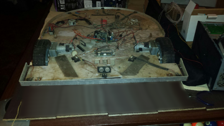
    All the major hardware was designed by me. The main frame is a custom welded steel frame. The main deck was fabricated from a piece of acrylic that I had gotten from someone who had used it originally for a science fair computer display. The blade motor carriage was designed to fit at 3 different levels for different blade cut heights.

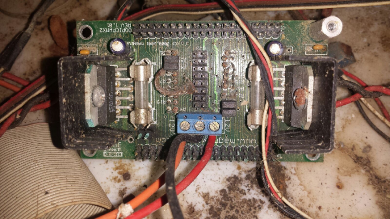
    For the electronics, I had started using an old robotics micro-controller called OOPic. With it, I had a dual H bridge motor controller to give it differential steering. The front and rear both had custom bent aluminum bumpers which could detect directional contact with the use of micro-switches around the edge. I had side looking IR distance sensors for short range side sensing, with a front mounted ultrasonic distance sensor for longer range of vision.

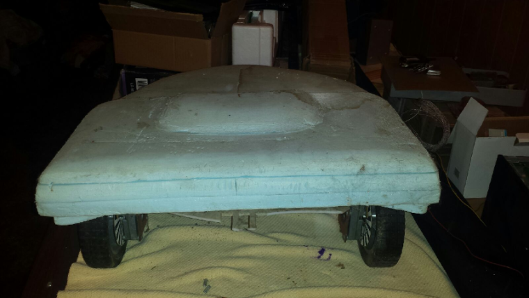
    I had gotten so far as to start designing an outer shell for it that I was going to make out of fiberglass. In some of the pics you will see the styrofoam shell mold I had started building.

    AFTER PULLING IT OUT OF STORAGE

    I didn't have it covered or protected, so in the time it has been in storage, the frame has rusted, motors and electronics are corroded, deck is dirty, the front of the acrylic platform broke off and the front part broke in two pieces. WHEW, that was a mouthful. Looking at this picture, you can see that it is in rough shape. This is before any cleanup work so I have a before and after view when it is done.
    0_1508737895580_upload-ed294247-a598-4800-b6ab-d36bd1643abc
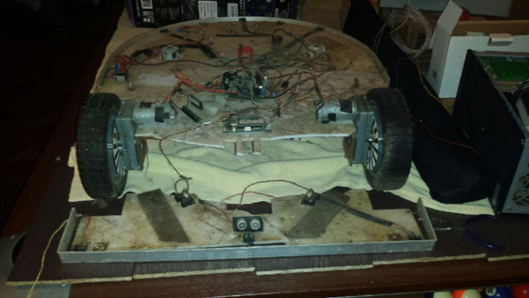
    I edited that picture in gimp to give an idea of what the full deck somewhat looked like.
    0_1508738055664_upload-ae4e0874-9796-4355-b8a9-710cf816314d

    THE GOAL

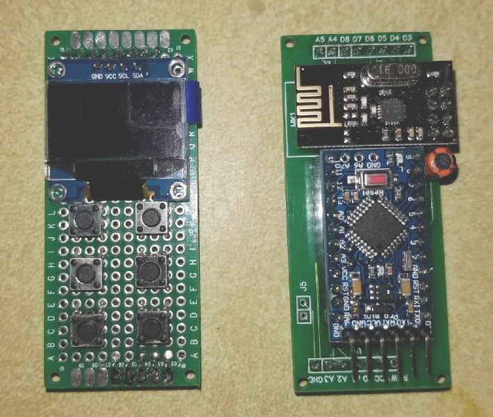
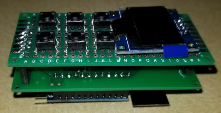
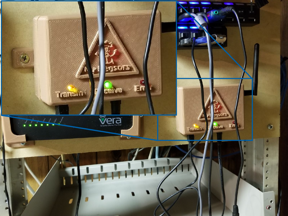
    The end goal of the whole thing is to hopefully get this thing operational. I would like to MySensorize some parts of it, though I haven't thought out exactly what parts yet. First thing is going to be to take it all apart, clean all of the parts, and then start rebuilding. I need to re-figure all of the electronics. I figure I can get better vision and control with newer and cheaper electronics.

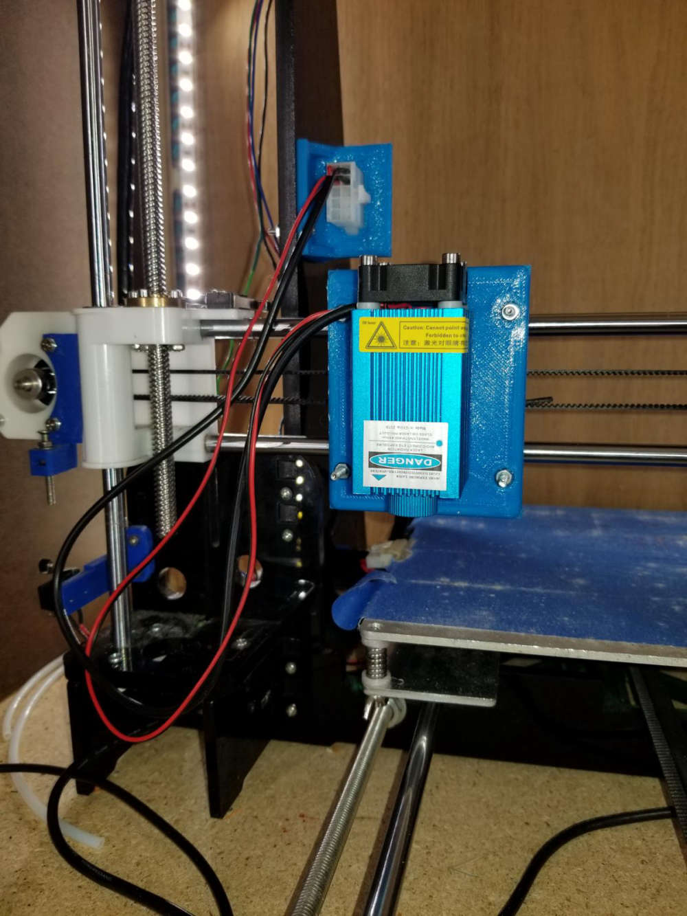
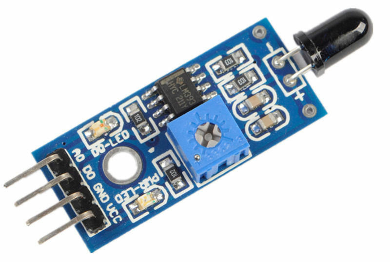
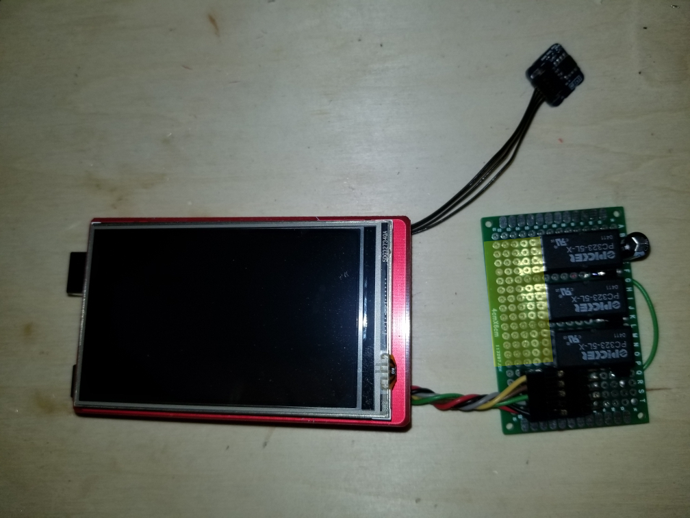
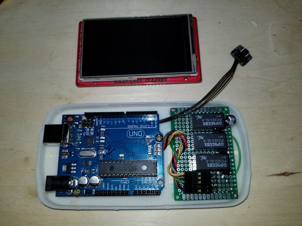
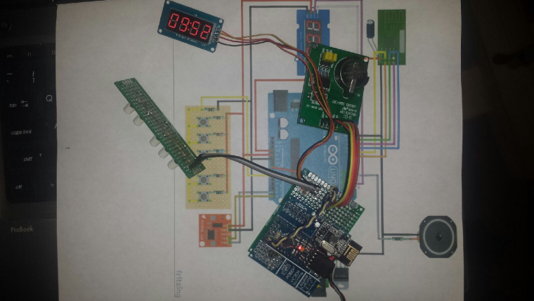
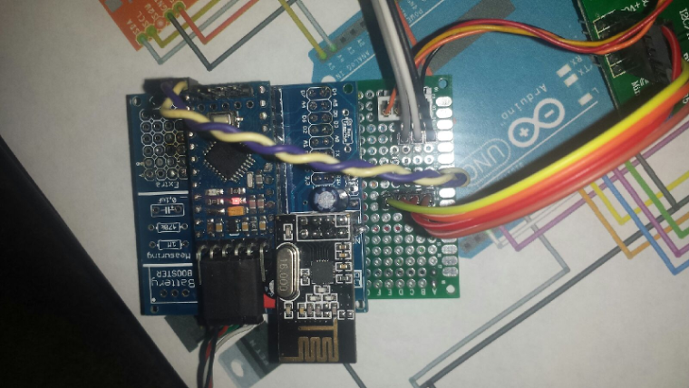
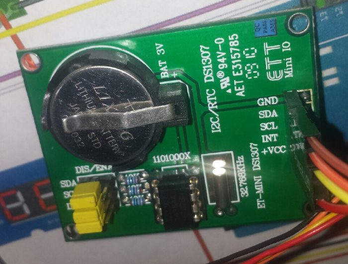
    Here are a few more teaser images.
    0_1508739333705_upload-709a3839-c39d-4c9e-9a60-85015889469e
    0_1508739404916_upload-31cff1a6-26cb-4a91-9a9f-74404fe200e0

    I actually have 17 pics of this, so instead of posting them all here, I put them in an image gallery on my website.
    https://dan.bemowski.info/image-gallery/nggallery/robotics/Mowbot

    This is probably going to be a long drawn out project, and I don't know at what intervals I'll post progress, but I will post progress at some points.

    My Project

  • MySensors weather station
    dbemowskD dbemowsk

    Here are a few more pictures of the new layout with the new anemometer cups.
    0_1499087266284_upload-2b958d54-e3bb-4ae1-9ba4-815bc9ac5f88
    0_1499087278053_upload-dec6c2b6-ee03-4891-9f89-161246ed722f
    0_1499087288381_upload-164b9af0-fe6c-4ebf-ab25-e675e10c41d7

    Enclosures / 3D Printing

  • My new website
    dbemowskD dbemowsk

    Just figured I'd give a plug for my newly converted website. The old site and CMS that ran it were out of date. I have converted to WordPress and hope to put information and tutorials related to my automation stuff and other things. I like the new look and feel of the site. Give it a look.

    http://dan.bemowski.info/

    General Discussion

  • Questions for a thermostat project.
    dbemowskD dbemowsk

    So this project at this point in time is not a MySensors based project, but I may make it into one in the future and use one for my home. That said,

    MY PROJECT

    My project is a digital thermostat using an arduino uno and a 3.2 inch touch screen TFT shield. This thermostat is going to replace the thermostat in my RV.
    One difference from an RV thermostat to a normal house thermostat is that the house system typically runs on 24 volts AC whereas the RV runs on 12 volts DC. My original plan was to use the incoming 12 volts to power the uno. The specs for the UNO say that you can put up to 12 volts in the barrel jack. The only problem I have with this is that the linear regulator that the UNO has gets quite hot when running it from 12 volts. This heat will no doubt affect the temp sensor that reads the open air temp. I need to find a reasonably small way to regulate 12 volts to 5 volts without a lot of heat.

    MY DESIGN:

    And now a bit about my design. I have most of this built and my firmware is nearly ready. I am designing it as an auto changover setup with a relay for fan speed (low or high). Here is the board setup that I have.
    thermostat setup
    The area of the board marked in yellow will be where the screw terminals will go for connecting it to the system. The 3 relays are heat, cool and fan. I was originally going to use 5 volt relays supplied from the 5 volt pin on the arduino. I found out that when two relays would trigger, the UNO would reset. I tried adding a capacitor to the power line near the relays, but that didn't help. I am changing the relays to 12 volt relays so I can just use the incoming 12 volts to power them. I am triggering them with NPN transistors connected to 3 digital pins.

    Here are a few more pics of the setup. I have designed and 3D printed a case for this also.
    boards mounted in case
    This is with the TFT shield in place.
    case with TFT shield
    And this is with the cover in place. The cover needs a little bit of cleanup work, but otherwise not too bad.
    alt text

    MY FIRMWARE

    And now a look at the firmware. The first image is the main screen. The main screen shows the current temp with the HVAC, fan status and set point on the right side of the screen.
    main screen
    The main screen has two touch areas, the gear in the upper left corner and the set point box. Touching the gear icon gets you to the settings page, seen here.
    settings screen
    When you touch to change any setting, it is stored in the EEPROM on the UNO allowing it to recover on the same settings if it were to loose power. Most of the settings are pretty self explanatory except for the threshold and changeover settings.

    The threshold value is either added or subtracted from the set point to offset when the heater or AC is switched on to know if it should have the fan on high or low. if the temp is with the threshold value of the setpoint, the fan is set to low, otherwise set it to high. On the RV, this just sets the fan to low or high. On a house multi-stage HVAC system it could switch stages.

    The changeover value tells the system how many degrees the temperature must go up or down from the setpoint before the system changes over from heating to cooling or vice versa.

    Clicking Exit at the bottom will take you back to the main screen.

    On the main screen, clicking anywhere in the box that shows the set point temp will take you to the setpoint screen.
    set point screen
    This screen is self explanatory in its function. The up and down arrows let you set a new setpoint, and Exit at the bottom will take you back to the main screen. The setpoint value is also saved to EEPROM on any change in value.

    My Project

  • Desktop 8 button scene controller
    dbemowskD dbemowsk

    So recently I had to change over one of my last remaining rooms that had X10 hardware over to MySensors. This happened to be our master bedroom which I had been using a couple of these X10 tabletop controllers:
    0_1546675522046_61a180c1-14e6-46df-99b4-05e84cc5890f-image.png
    My wife loved the fact that she had control of the light and ceiling fan right next to the bed. When I switched over to MySensors control of the room with my Vera controller, I was no longer able to use the old X10 controller. I had thought of gutting the controller and rebuilding the electronics, but that seemed like more work than designing my own controller. I started mocking up a design in OpenSCAD and here is what I came up with.

    This is the full mocked view showing the 8 buttons.
    0_1546674026628_512d5a30-2da7-4566-9f4b-0020254e5d0e-image.png

    This is with the cover off and the mock of the Easy Newbie Board by @sundberg84 in place to see how it would fit. The hole in the back of the case is for a DC power cable. I figured rather than have to design in a power supply, I figured I would just use a 5 volt wall wart power supply.
    0_1546674229935_36e80dd8-2eab-4b2a-912f-5d1728ab84f9-image.png

    I had a couple of these laying around, so this will be my DC in jack. wired through the small hole in the back directly to the raw in to the Easy Newbie board.
    0_1546674893401_91f4cdc0-755e-495c-ad90-4b3d89db33d4-image.png

    This is the underside of the top cover showing the mock up of the 40 x 60mm proto-board with switches mounted to it, again to size up the fit.
    0_1546675142295_12b1df22-154e-4737-ba2a-61744f6c0e1f-image.png

    I currently have the first revision of the case on the printer. I may at some point add an OLED or LCD display to a future revision for feedback, but for now just to see if the idea is sound, I am keeping it as simple as possible.

    Once I get this finished and know it works I will post it to thingiverse. If anyone had comments or questions, feel free to post them here.

    Enclosures / 3D Printing

  • What did you build today (Pictures) ?
    dbemowskD dbemowsk

    So for some time now I have been working on a conversion to my 3D printer to allow me to change between different tool heads easily, thus increasing the versatility of the machine. To jump right in and give a little background on the mod, I have a plate that mounts to my X carriage that has 4 10mm neodymium magnets in it. These magnets hold the tool in place that will be used which also has 4 magnets in it's mounting plate.0_1549168718079_Resized_20181230_084440_8356-2.jpg
    0_1549168740823_Resized_20181230_084411_8868-2.jpg
    The first tool that I did was my 3D printer head. I obviously did that one first because I would need that to make future parts and tool heads to expand the machine. Here is my 3D printer head mounted to the working assembly.
    0_1549169544562_Resized_20190118_013816_2670.jpg
    Another tool head that I made for this is my simple pen plotter tool for drawing.
    0_1549169817834_Resized_20190202_225547_6180.jpg
    Here is a sample of something I did with the pen plotter using fine point sharpie markers. The left is the original image, and the right was done with the plotter.
    0_1549170644769_0f86124a-cf32-4e8a-a078-f2e4870df5a3-image.png
    The most recent tool head that I did was my laser engraver tool. This tool is the main reason for this post. This is the 6 watt laser module mounted to the carriage.
    0_1549170198674_Resized_20190202_230033_4069.jpg
    So what I am looking to do with this on the MySensors end of things is to build some sort of flame sensor that can monitor the engraving operation to indicate a small fire and take some sort of action, and also report it to my vera controller. Exactly what action I would have it take I have not figured out yet. If anyone has suggestions I'm all ears. I was thinking of something that could easily extinguish the small flame. As for the flame sensor, I know they make these small flame sensor modules, but I don't know how reliable they are, ore even how they work.
    0_1549171496732_6c6a2026-c4f2-408a-83a5-745076ec537d-image.png

    For anyone interested, here is a sample engraving on a piece of thin plywood. The left image is the original. The center is at a low resolution, and the right one was at a high resolution.
    0_1549172116707_f5a6f311-a35e-4363-8e9d-e4c3cb6460a6-image.png
    One other thing that I want to test with this is I've seen people that make circuit boards with these. They spray a layer or two of paint on their blank copper clad and then laser etch their pattern on the painted surface. Then they run it through their ferric chloride or other etching solution. Finally, sand off the layer of paint.

    Any suggestions or help people can give is greatly appreciated. Thanks for viewing.

    General Discussion

  • S_HVAC in domoticz
    dbemowskD dbemowsk

    @diamantmatch said:

    i guess this means that V_HVAC_FLOW_STATE and V_HVAC_SPEED are not implemented in domoticz yet?

    If you read through this post that I have out there for the RS485 bridge that I am working on for my RCS thermostat, there is some information regarding this in there. Regarding your comment directly, @pjr stated that V_HVAC_FLOW_STATE, V_HVAC_FLOW_MODE and V_HVAC_SPEED are not implemented in Domoticz yet.

    There is some other useful information in that post if you are looking to do something with your thermostat. My RS485 bridge is still a work in progress, but I had to put it on hold for a while as I am a beta tester for a different thermostat, so I currently have my RCS thermostat disconnected. I think it is worth it though to post to the Domoticz community that this would be a useful implementation.

    Domoticz

  • UI5 Mysensors library 2.0 gateway issues
    dbemowskD dbemowsk

    So it appears that the saga has been solved. The problem in fact WAS with the FTDI adapter. In all of the testing that I did I am guessing that the FTDI's receive data was working, but the transmit data was the issue. I put my spare FTDI on and Vera was detecting devices left and right. I think I am going to have to redo the inclusion because it said that there were 5 devices found, but nothing was added to Vera, but like I say, the devices did not appear to be presenting at the time.

    I want to say though that I appreciate all the time that people spent trying to help me get this going. This forum is a GREAT crowd of people.

    Vera

  • What did you build today (Pictures) ?
    dbemowskD dbemowsk

    Working on a smart clock project. Need to make some major code modifications to the example, but should work. I have a test sketch that just passes the time from the RTC to the display, so I know that is all working.

    0_1509332623272_upload-b119edce-2231-4ce0-9b9c-c5bd4ca629d5
    0_1509332689597_upload-2dbe753a-35af-4793-bf46-52669aed4bb0
    0_1509332950856_upload-a1744ea1-3830-4cf6-816b-f273431a596b

    General Discussion

  • US decora style wall switch
    dbemowskD dbemowsk

    So I am trying to design a wall switch that will work similar to the older 4 (8) button X10 XPT switches that I have in some places in my house. For those that don't know what these switches are like, here is a pic.
    alt textalt text
    I have also seen other switches out there that have an LED next to to each button such as in the second pic. Much like the XPT switches, the buttons on these will just transmit back to the MySensors gateway or possibly directly to another relay or dimmer node.

    Design:
    So here are my thoughts on how the design of the switch would be. The faceplate would be made from a decora style blank such as one of these:alt text
    The design would be something like this:
    alt text
    I am thinking that this could be laser engraved onto the decora blank. The switches would be laid out like this on the top pcb so as to have a switch under each engraved tab:
    alt text
    I tested a couple switches on a protoboard and when the board sits on the back of the blank plate, the caps of the buttons gently rest on the back of the wall plate. The laser engraved areas on the front should flex just enough to hit the buttons underneath. The LEDs next to each row will just be a simple on/off status LED.

    Wiring:
    The wiring should fit for all of the components if my calculation is correct. Six data lines are needed for the switches (4 rows and 2 columns), and 4 lines for the status LEDs. After wiring the radio to the node there are data lines 3 through 8, and analog lines A0 through A3. The analog lines would be used for the LEDs as there are 4 of them. The 6 digital lines would be used for the push buttons. The wiring for the switch board would look something like this:
    alt text
    The LEDs would be 1.8mm LEDs like these:
    1.8mm LEDs

    Connecting the controller:
    What has been shown so far has just been the switch board. The idea is that the switch board would stack on to the controller board with one or two header connectors. The controller board would use a PCB the same size as the switch board. There is plenty of room on the second board to put the nano and the nRF radio along with the 3.3v regulator.

    Power
    My next hurdle in this is figuring out power. I am thinking of using another board stacked on to the assembly and using one of these AC/DC converter.

    Design advantages
    Here are some key advantages to this design.

    • The 3 board design makes it modular. You basically have your power supply board, your processor board, and your switch board. This makes switching parts that may fail easier.
    • With the front switch panel being a plug in module, other switch configurations can be created to change the functionality. This does not have to be only for switches, as you could build other sensors or indicators that could fit a standard decora style wall plate.
    • If status LEDs are not used that would open up 4 more lines for more switches or other sensors.

    Conclusion
    So far these are all just ideas. I am open to comments and criticisms on any thoughts or ideas that I have noted. Any ideas on where I can get some of the parts done at like the laser cutting and possibly a good PCB manufacturer, that would all help too. I haven't looked yet, but I am assuming that there is a matrix switch assembly sketch out there somewhere that I could use as an example.

    I will post more as this project moves on.

    My Project
  • Login

  • Don't have an account? Register

  • Login or register to search.
  • First post
    Last post
0
  • MySensors
  • OpenHardware.io
  • Categories
  • Recent
  • Tags
  • Popular