
What did you build today (Pictures) ?
-
@yveaux said in What did you build today (Pictures) ?:
The original 2-wire fan that came with the power supply casing made an incredible amount of noise.
Using PWM to reduce its velocity made it even more noisy :imp:Less funny that way but did you try to lower the PWM frequency of the atmega to it's minimum ? I had the same problem with the fan I put in my fridge cabinet and low PWM frequency solved it.
-
An RC filter could probably also make wonders for the fan. I had to add one for the parts fan on my 3D printer. Couldn't control the speed with PWM without the RC filter..
Btw. probably a bit over the top of using an arduino as fan control? Unless you plan on adding a NRF radio, and report the temperature + PWM duty cycle to your mysensors system, and store the values in influxdb? ;)
-
An RC filter could probably also make wonders for the fan. I had to add one for the parts fan on my 3D printer. Couldn't control the speed with PWM without the RC filter..
Btw. probably a bit over the top of using an arduino as fan control? Unless you plan on adding a NRF radio, and report the temperature + PWM duty cycle to your mysensors system, and store the values in influxdb? ;)
@tbowmo said in What did you build today (Pictures) ?:
Btw. probably a bit over the top of using an arduino as fan control?
Really? How so? Seems like the end result will be as quiet as possible, yet avoids stalling.
-
@tbowmo said in What did you build today (Pictures) ?:
Btw. probably a bit over the top of using an arduino as fan control?
Really? How so? Seems like the end result will be as quiet as possible, yet avoids stalling.
@neverdie said in What did you build today (Pictures) ?:
@tbowmo said in What did you build today (Pictures) ?:
Btw. probably a bit over the top of using an arduino as fan control?
Really? How so? Seems like the end result will be as quiet as possible, yet avoids stalling.
Indeed! I thought of going the analog way, but the final solution would be more expensive, I didn't have the parts at hand, it wouldn't have as many features and it would have cost me a lot more time...
-
An RC filter could probably also make wonders for the fan. I had to add one for the parts fan on my 3D printer. Couldn't control the speed with PWM without the RC filter..
Btw. probably a bit over the top of using an arduino as fan control? Unless you plan on adding a NRF radio, and report the temperature + PWM duty cycle to your mysensors system, and store the values in influxdb? ;)
-
a 555 and a couple of resistors / capacitors.. ;)
https://electronics.stackexchange.com/questions/91102/555-temperature-controlled-pwm
But then again, I recon that most of us might have more atmega328 based boards, than 555's in the parts bin :)
about the RC for PWM, it was meant as a hint for others that might fight problems with a fan that they couldn't control properly with PWM..
-
a 555 and a couple of resistors / capacitors.. ;)
https://electronics.stackexchange.com/questions/91102/555-temperature-controlled-pwm
But then again, I recon that most of us might have more atmega328 based boards, than 555's in the parts bin :)
about the RC for PWM, it was meant as a hint for others that might fight problems with a fan that they couldn't control properly with PWM..
-
a 555 and a couple of resistors / capacitors.. ;)
https://electronics.stackexchange.com/questions/91102/555-temperature-controlled-pwm
But then again, I recon that most of us might have more atmega328 based boards, than 555's in the parts bin :)
about the RC for PWM, it was meant as a hint for others that might fight problems with a fan that they couldn't control properly with PWM..
@tbowmo said in What did you build today (Pictures) ?:
a 555 and a couple of resistors / capacitors..
https://electronics.stackexchange.com/questions/91102/555-temperature-controlled-pwmStill, no tacho readback to detect stalled fans, no temperature sensor verification or overtemperature warning, no initial fan spinup and little control over how the fans reacts to temperature changes....
-
-
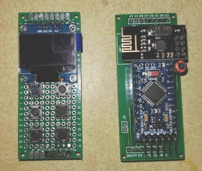
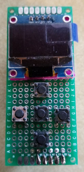
Though not fully finished, I am prototyping a new in-wall switch/scene controller with an integrated 128x64 OLED display. The design is made to fit my decora wall switch design that I had posted a while back. Here is a mock up of how I think the keypad and screen will be layed out.
!
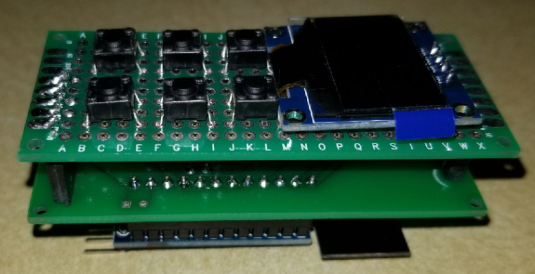
For the screen, I am hoping to display the current room temperature and possibly the outside temp. I can also scroll messages across the screen if needed. I can also do some custom graphics and icons.
I have tested the display connected to my uno with the Adafruit sample code and think it does a nice job. This is not my video, but it is the same sample code that I used to test it.
https://www.youtube.com/watch?v=ldq0-IXl_GMI'll post more as I get further along.
Vera Plus running UI7 with MySensors, Sonoffs and 1-Wire devices
Visit my website for more Bits, Bytes and Ramblings from me: http://dan.bemowski.info/ -
Well as you can see, my prototyping skills are not at the level of @dbemowsk (always interested in the under side of the boards, mine look .. yeah a mess?), however I managed to create this enclosure (once closed looks nice enough).
It should control the programmable LED lights in my livingroom (900 pieces).The board is powered 5v from the same power supply as the LED's. In addition it needs to measure the lux in the livingroom to decide if it is dark enough to turn on the lights.
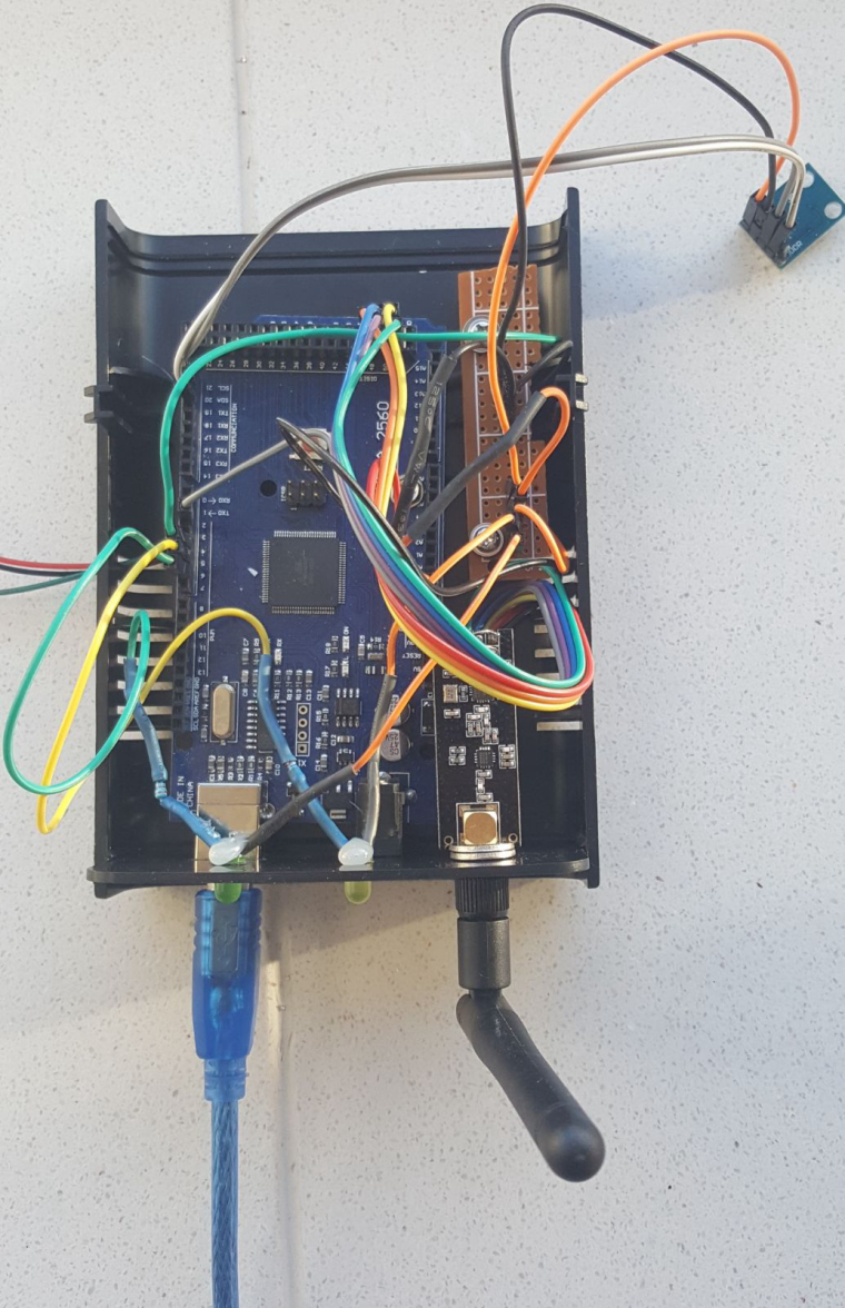
Initial tests looked okay, however after finding 56 effects in the Doll House of @Yveaux I decided to use that FX library as well. However the Arduino Mega is out of RAM to accomodate a full controll of the 900 LEDS. It will only control around 650 LEDS with that FX library.
After being in contact with @Yveaux we decided to use an ESP solution. I have a spare NodeMCU v3 that can house the ESP gateway sketch and will have enough memory to controll the LEDs. Well now I have to look for a nice prototyping thing/case for the NodeMCU and add a level shifter as well. The LED's control line wants to be controlled by at least 3,7v.
This is the nice thing about these kind of projects.. "There is always something to do"
-
Well as you can see, my prototyping skills are not at the level of @dbemowsk (always interested in the under side of the boards, mine look .. yeah a mess?), however I managed to create this enclosure (once closed looks nice enough).
It should control the programmable LED lights in my livingroom (900 pieces).The board is powered 5v from the same power supply as the LED's. In addition it needs to measure the lux in the livingroom to decide if it is dark enough to turn on the lights.
Initial tests looked okay, however after finding 56 effects in the Doll House of @Yveaux I decided to use that FX library as well. However the Arduino Mega is out of RAM to accomodate a full controll of the 900 LEDS. It will only control around 650 LEDS with that FX library.
After being in contact with @Yveaux we decided to use an ESP solution. I have a spare NodeMCU v3 that can house the ESP gateway sketch and will have enough memory to controll the LEDs. Well now I have to look for a nice prototyping thing/case for the NodeMCU and add a level shifter as well. The LED's control line wants to be controlled by at least 3,7v.
This is the nice thing about these kind of projects.. "There is always something to do"
@sincze I've done and seen a lot worse than this. Good job. Any particular reason you chose to use a Arduino Mega?
Vera Plus running UI7 with MySensors, Sonoffs and 1-Wire devices
Visit my website for more Bits, Bytes and Ramblings from me: http://dan.bemowski.info/ -
@sincze I've done and seen a lot worse than this. Good job. Any particular reason you chose to use a Arduino Mega?
@dbemowsk Well first I started with my all time favourite... the Nano, as I have prototyping boards available.;-) but even with some simple light shows it did not have enough memory to hold de states of each individual 900 LEDs.
I moved to the Mega. as it has more memory. My sketch worked fine so I started to build the node in its box. I also looked at the Github for the Doll House inspiration. I found the library that had 56 effects. So I thought why not use that one... Migrated my sketch, did a few tests with 300 LEDS, completed the enclosure and only than found out It could not controll all the 900 leds, due to memory issue. Insufficient RAM.
But as this forum is a learning curve for me please feel free to share your thoughts. I always look at examples from others and see what I can do with it myself. I don't have fancy PCB equipment, justs a soldering iron and my own Aliexpress wearhouse with components ;-)
-
@dbemowsk Well first I started with my all time favourite... the Nano, as I have prototyping boards available.;-) but even with some simple light shows it did not have enough memory to hold de states of each individual 900 LEDs.
I moved to the Mega. as it has more memory. My sketch worked fine so I started to build the node in its box. I also looked at the Github for the Doll House inspiration. I found the library that had 56 effects. So I thought why not use that one... Migrated my sketch, did a few tests with 300 LEDS, completed the enclosure and only than found out It could not controll all the 900 leds, due to memory issue. Insufficient RAM.
But as this forum is a learning curve for me please feel free to share your thoughts. I always look at examples from others and see what I can do with it myself. I don't have fancy PCB equipment, justs a soldering iron and my own Aliexpress wearhouse with components ;-)
@sincze I should have known. All you had to say was memory and it would have made sense, or should I say sincze. LOL. With needing to hold states of 900 LEDs, I am going to guess that they are WS2812 LED strips.
Vera Plus running UI7 with MySensors, Sonoffs and 1-Wire devices
Visit my website for more Bits, Bytes and Ramblings from me: http://dan.bemowski.info/ -
Though not fully finished, I am prototyping a new in-wall switch/scene controller with an integrated 128x64 OLED display. The design is made to fit my decora wall switch design that I had posted a while back. Here is a mock up of how I think the keypad and screen will be layed out.
!
For the screen, I am hoping to display the current room temperature and possibly the outside temp. I can also scroll messages across the screen if needed. I can also do some custom graphics and icons.
I have tested the display connected to my uno with the Adafruit sample code and think it does a nice job. This is not my video, but it is the same sample code that I used to test it.
https://www.youtube.com/watch?v=ldq0-IXl_GMI'll post more as I get further along.
@dbemowsk I like your buttons-OLED a lot. It would be nice to have available a generic module like this with a screen and buttons and which "just works" to use on different projects. Nice work!
-
@dbemowsk I like your buttons-OLED a lot. It would be nice to have available a generic module like this with a screen and buttons and which "just works" to use on different projects. Nice work!
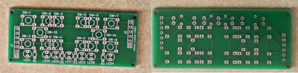
@neverdie I am hoping to soon have all of my boards posted on openhardware.io. I am just waiting for a reply on a thread I posted last night on what OHL to use when I upload them. I currently have a power supply board, the controller board that you see in the pics above, and a universal switch board that allows you to build it into everything from a single paddle switch to an 8 button scene controller. All of this fits a standard decora style US wall switch box. I designed the controller to be somewhat universal which is what gave me the flexibility for this design. I had thought about a similar design with this OLED display in which the buttons were layed out in an up, down, left, right and center select (U, D, L, R, S) configuration. If I ever get around to designing a board for this, I might see if it is possible for me to fit the buttons in a multi-configuration layout similar to my original button board where you can choose to make the 6 button layout like in my pics, or the U, D, L, R, S layout.
-
@dbemowsk I like your buttons-OLED a lot. It would be nice to have available a generic module like this with a screen and buttons and which "just works" to use on different projects. Nice work!
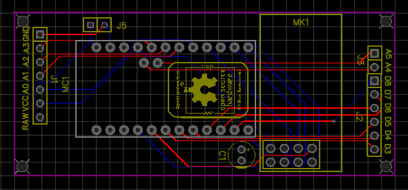
@neverdie As far has having a generic module, the display and button board, or even my original button board can be used with other things. The key is just knowing the connections, and you could plug these on to any header in that configuration. Below is the layout of my controller board, but if you layed out headers in the configurations I have on this board, you could use any of my switch boards.
-
-
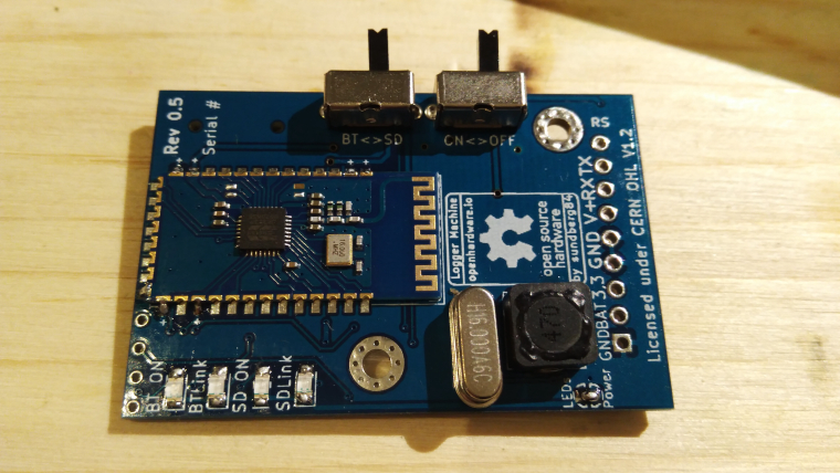
Assembling and testing rev 5 tonight.
-
So last night I got the display connected and I now have the Adafruit sample code running on it:
https://youtu.be/knaLySC4X6ITonight I will be installing the buttons and hopefully working on some test code for the buttons and the screen. Here is my proposal for the switch wiring. The red traces are for the columns, and the blue are for the rows.
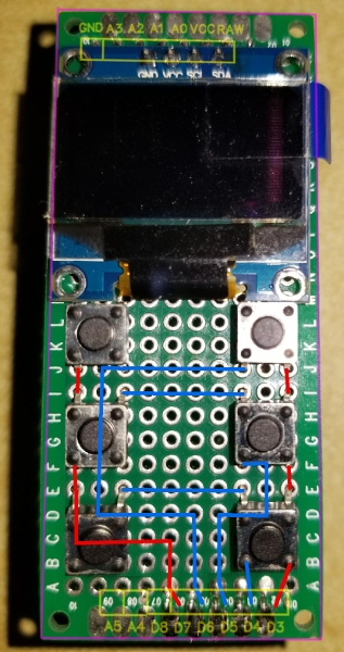
One thing that I would like to do with this is to possibly display some animated graphics for the current weather condition. Seeing the falling stars at the end of the Adafruit test code made me think of rain or snow falling. Something like that might go outside the limits of the pro minis memory, but hey, never hurts to try.
Vera Plus running UI7 with MySensors, Sonoffs and 1-Wire devices
Visit my website for more Bits, Bytes and Ramblings from me: http://dan.bemowski.info/









Hello! It looks like you're interested in this conversation, but you don't have an account yet.
Getting fed up of having to scroll through the same posts each visit? When you register for an account, you'll always come back to exactly where you were before, and choose to be notified of new replies (either via email, or push notification). You'll also be able to save bookmarks and upvote posts to show your appreciation to other community members.
With your input, this post could be even better 💗
Register Login