Is there anyone that either still uses a Vera controller or knowssomething about how they work with Alexa? My issue is that my thermostat bridge had the Arduino Pro Mini die and I had to flash a new one. When I did this I had to re-discover it with MySensors in Vera. I then had to delete the node from Alexa to add the new one, but when I go to the list of discoverable devices it doesn't show up. I can control it fin on the Vera but can't add it to Alexa.
Posts made by dbemowsk
-
MySensors node not working with Alexa on my Vera
-
RE: Old hardware migration
@OldSurferDude My old 2.0 setup is with nRF24L01 radios. This is a link to the thread on some light switches that I designed and built.
https://forum.mysensors.org/topic/7376/us-decora-wall-switch-continued/2
I am aware that you cannot have two MQTT gatways. When I designed my old setup I was not that familiar with MQTT so I never ended up implementing it. On the home assistant server that I have set up though, I have installed the MQTT broker on there so I should be able to comunicate with any MySensors stuff over MQTT in the future devices I make/set up. As I mentioned, I do have a Home Assistant box that I have started about 4 months ago and eventually want to migrate my Vera equipment to the HA box.As for the YAML and Python, I'll muddle my way through. used to program in PHP and have done enough on Arduino that I'm sure it won't hurt my brain too much.
-
RE: ๐ฌ In-wall scene controller OLED keypad
@Michael-Link I have been out of touch with MySensors for some time now and looking to slowly get back into it. I created this and a few other boards back in 2018 All of the GERBER files for this are in the "Design Files" tab. Those you should be able to send to JLC PCB or one of the other fab houses and have some made. This was designed to be used with 2 other boards that I designed. There was the processor board and the power supply board. The processor board was designed in a way that I could use a couple different switch boards. This one and a universal multi-switch board that had multiple configurations. If you look here you will see my other boards.
-
Old hardware migration
So I have been out of touch with MySensors for a few years now. I still have a bunch of hardware running that uses MySensors 2.0 I believe. It is all connected to my old Vera controller. I am working on setting up a machine to run Home Assistant and plan to slowly migrate hardware to the new system. My question is, if I configure a new 2.3.2 gateway and connect it to the Home Assistant box, will my 2.0 hardware be backwards compatible and connect to the new gateway? Also, is it possible for me to run 2 NRF24 gateways at the same time without the hardware freaking out? I do have the HomeAssistant box configured as an MQTT gateway and may put new hardware on the MQTT side going forward. What are peoples thoughts on the best approach. The migration will most likely be S L O W.
Any input is appreciated.
-
RE: Moisture penetrates my outdoor enclosures...
This may sound crazy, and may not be an option after saturation, but what about putting a silica gel pack in there?
-
RE: Website forum search feature [is broken]
@mfalkvidd No problem, Now that I know that I'll just do some manual browsing if I need to find answers.
-
Website forum search feature [is broken]
So I have been out of the loop with MySensors for a few years, but still run some MySensors 2.0 hardware that I built years ago, and it is still working. I am currently running a Vera Plus home controller and it is working for the most part, but I am thinking of switching either back to Domotcz or to Home Assistant on a Raspberry Pi. This brings me to my question. Being that I have been out of the loop for a while, I am trying to find some information, so I am trying to use the search feature of the forum before I post new topics that have been answered already. The problem is that pretty much every search I do comes up saying "No matches found". Is there a problem with the search feature of the forum?
-
RE: Questions about an old setup
@Nigel31 and @ejlane, My Vera controller has a built in app/plugin for alexa. My wife uses it alot and would be sad to see that functionality go. So Controlicz is a skill that I would have to add to Alexa? Currently the plugin for Vera uses the built-in smart home feature of Alexa. As I recall, I didn't have to set up a special skill for it to work on the Vera. I did however have to install the app on the Vera that would talk to it. I think that does use the vera portal to work though as I have to log in to my Vera account to be able to update my Vera connected devices.
-
Questions about an old setup
So I have been out of the MySensors loop for a number of years now, but still have a number of version 2.0 devices that are still running in my house with my Vera Plus controller. Prior to the Vera Plus I was running Domoticz on an old Orange Pi and I am thinking of possibly switching back to that as there were some features of it that I liked. I have a few Raspberry Pi 2B+ boards that I could run it from. My question is, will my old 2.0 NRF24L01 gateway still work with the latest version of Domoticz and recognize my devices? Another question has to do with my sprinkler controller. The sprinkler controller was part of the reason I switched to the Vera in the first place. The reason being that Domoticz, at the time, didn't support the variables 1,2 and 3 for setting the 2 zone time options and the zone name like this:
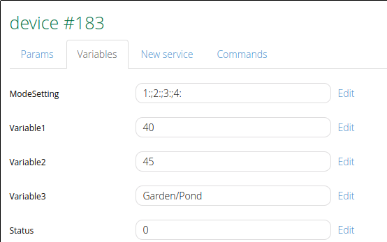
I am wondering if Domoticz has gained better support for these things or if I will still have these hangups with the sprinkler controller?
The last thing is my alexa devices. I currently have this working with my Vera controller and am able to control all of my MySensors devices. I see that there is a skill called Controlicz.Has anyone used this and if so, ho well does it work for the MySensors hardware?
I remember this being a GREAT community of people. I am open for any insight into this issue. I know my Vera controller is getting old and will one day die on me leaving me stranded. I want to catch things before that day comes.
Thanks all.
-
RE: US decora style wall switch
@alex_the_techy I have had an A8 for just over 2 1/2 years now and it has been a relatively good entry level printer. Most of these entry level printers have some quirks about them, but they give you a good start into 3D printing. It does have an acrylic frame which is not quite as sturdy or durable as the aluminum extrusion frame that something like the Ender 3's or the Creality printers have. You can pick up an Ender 3 now for less than $200 US at aliexpress which is right around the same price as an A8. I would go with that over an A8 if I were to buy one these days. Many people that buy the A8 printers end up doing an AM8 frame conversion on them which basically gives you a frame similar to the Ender 3. I am not sure what the cost of the AM8 extrusion parts cost, but whatever the price is, it's too much when you can start out with the Ender 3 for around the same price as buying an A8 and you don't have to go through the hassle of the conversion, which by the way requires some 3D printed parts.
-
RE: Mini lightshow project ideas
Another thing that might be cool would be to figure out a way to do something with EL wire. If you are unfamiliar with EL wire, the EL is for ElectroLuminescent. You can get many different colors of EL wire and a controller from SparkFun. https://www.sparkfun.com/products/12781
And here is an example of something someone did with EL wire.
https://www.youtube.com/watch?v=1lGfMqEstKA -
RE: Mini lightshow project ideas
On the lines that @TheoL was talking, here is some information on doing DMX with Arduino. https://playground.arduino.cc/Learning/DMX/
-
RE: Best sensor for falling alert
@nca78 said in Best sensor for falling alert:
a LIS3DH will use 50-100 times less current for free fall detection (between 6 and 11ยตA), ADXL345 over 10 times less (40ยตA)
That is an excellent point. If using it for personal monitoring, quiescent current draw would definitely be a factor. The longer you can have the device last on a battery charge the better.
I had just used the MPU-6050 for building a recovery parachute system for my drone in which I needed free fall detection, and it worked well which is why I commented on that one.
-
RE: Best sensor for falling alert
@nca78 said in Best sensor for falling alert:
There are accelerometers with built-in free fall detection, you should use one of those.
The MPU-6050 has built in free fall detection using an interrupt.
-
RE: Best sensor for falling alert
@bjacobse I have done a little bit of work with the MPU-6050 IMU sensor (made a servo based 3 axis camera gimbal and a free-fall sensor for deploying a recovery parachute for my drone). I would think that with the MPU-6050 you should be able to distinguish between the two scenarios you mentioned. I can't say for sure, but if you looked at the data from the sensor in the two different scenarios I would think that you would be able to find some discernible difference and be able to code for that type of scenario. I think it would be worth doing some tests to see. The sensors are cheap.
-
RE: Questions for a thermostat project.
@nagelc Just ordered one of those buck converters from Digikey. Thanks for the suggestion. That might fix my whole issue.
-
RE: Questions for a thermostat project.
@mfalkvidd and others. I am aware of what buck converters are and have used them before, what I was trying to avoid was changing the design of the case to make more room for something like that, but I guess if it comes down to it I may have to. I was hoping that someone might have a solution that might fit my space constraints. I like the one that @nagelc suggested as it looks like it might fit in the space I have. Another option I thought of if I had to change the size of the case was to use a couple batteries. I have some extra 18650's in my parts bin, I would need to check the current draw to determine how long they would last powering the UNO and the TFT shield.
As for the relays, I am switching them from the original 5 volt coil ones to 12 volt coils. I have decided to power them from the 12 volt supply as I should have plenty of current from that to hold a relay or two since that comes from the house batteries of the motorhome. There would never be more than two relays energized at one time since one relay is for heating and one for cooling, So it would either be a heating or cooling relay and possibly the fan relay being powered at any given time. I like the suggestion @skywatch made about using latching relays to save power, the only problem in using those is that I am limited to 3 data lines (D0 - D2) because of the TFT shield. My understanding of latching relays is that there are two types. Single coil which uses reversing the polarity for set and reset, or the dual coil type which use one coil for set and the other for reset. I think in either case I would have to use more than one data line for each relay which won't work.
-
RE: Questions for a thermostat project.
My main question with this was what is a small cheap and cool (literally) way of getting the 5V I need for the UNO from my 12 volt supply. Preferrably something other than a linear regulator.
-
Questions for a thermostat project.
So this project at this point in time is not a MySensors based project, but I may make it into one in the future and use one for my home. That said,
MY PROJECT
My project is a digital thermostat using an arduino uno and a 3.2 inch touch screen TFT shield. This thermostat is going to replace the thermostat in my RV.
One difference from an RV thermostat to a normal house thermostat is that the house system typically runs on 24 volts AC whereas the RV runs on 12 volts DC. My original plan was to use the incoming 12 volts to power the uno. The specs for the UNO say that you can put up to 12 volts in the barrel jack. The only problem I have with this is that the linear regulator that the UNO has gets quite hot when running it from 12 volts. This heat will no doubt affect the temp sensor that reads the open air temp. I need to find a reasonably small way to regulate 12 volts to 5 volts without a lot of heat.MY DESIGN:
And now a bit about my design. I have most of this built and my firmware is nearly ready. I am designing it as an auto changover setup with a relay for fan speed (low or high). Here is the board setup that I have.
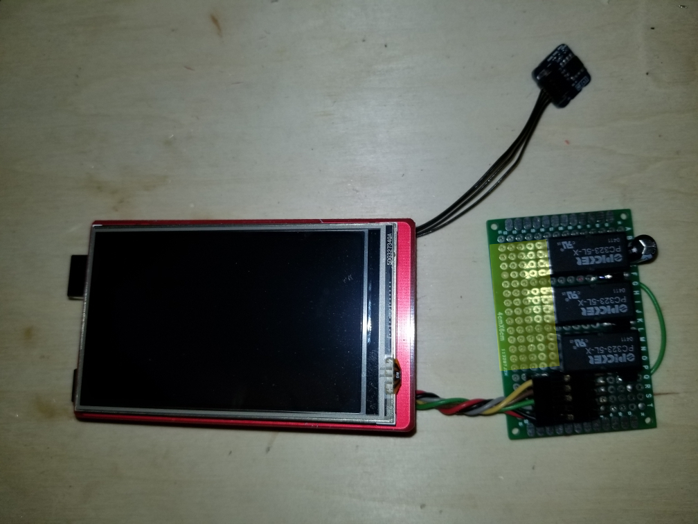
The area of the board marked in yellow will be where the screw terminals will go for connecting it to the system. The 3 relays are heat, cool and fan. I was originally going to use 5 volt relays supplied from the 5 volt pin on the arduino. I found out that when two relays would trigger, the UNO would reset. I tried adding a capacitor to the power line near the relays, but that didn't help. I am changing the relays to 12 volt relays so I can just use the incoming 12 volts to power them. I am triggering them with NPN transistors connected to 3 digital pins.Here are a few more pics of the setup. I have designed and 3D printed a case for this also.
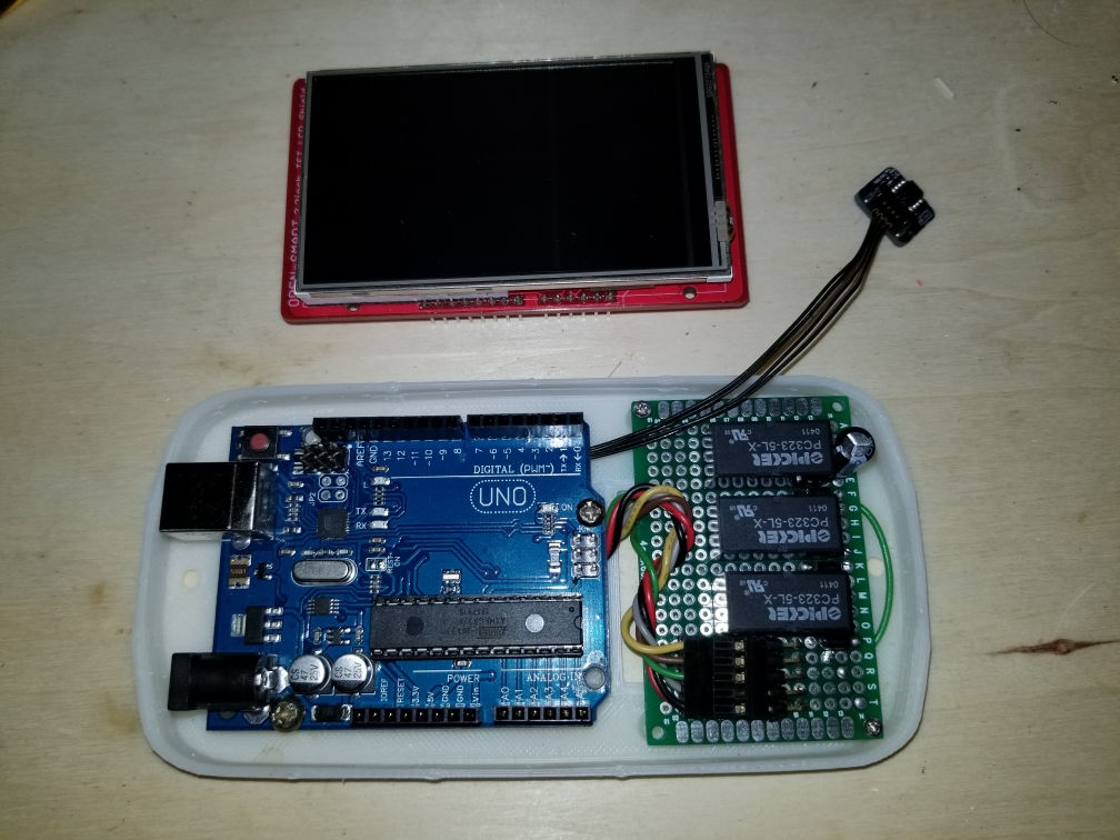
This is with the TFT shield in place.
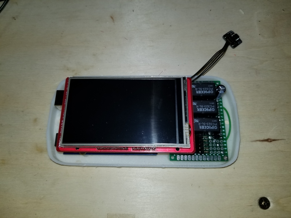
And this is with the cover in place. The cover needs a little bit of cleanup work, but otherwise not too bad.
MY FIRMWARE
And now a look at the firmware. The first image is the main screen. The main screen shows the current temp with the HVAC, fan status and set point on the right side of the screen.
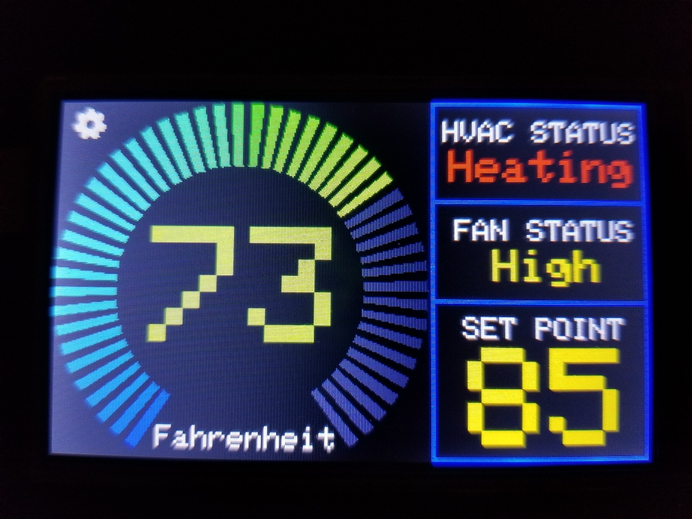
The main screen has two touch areas, the gear in the upper left corner and the set point box. Touching the gear icon gets you to the settings page, seen here.
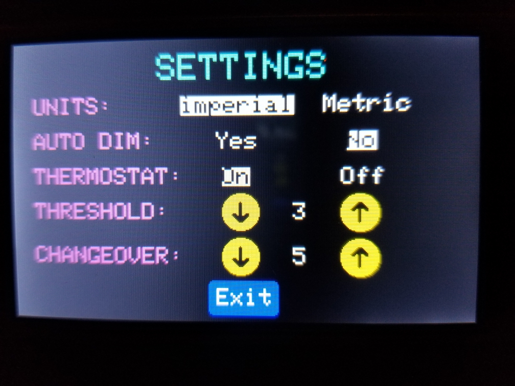
When you touch to change any setting, it is stored in the EEPROM on the UNO allowing it to recover on the same settings if it were to loose power. Most of the settings are pretty self explanatory except for the threshold and changeover settings.The threshold value is either added or subtracted from the set point to offset when the heater or AC is switched on to know if it should have the fan on high or low. if the temp is with the threshold value of the setpoint, the fan is set to low, otherwise set it to high. On the RV, this just sets the fan to low or high. On a house multi-stage HVAC system it could switch stages.
The changeover value tells the system how many degrees the temperature must go up or down from the setpoint before the system changes over from heating to cooling or vice versa.
Clicking Exit at the bottom will take you back to the main screen.
On the main screen, clicking anywhere in the box that shows the set point temp will take you to the setpoint screen.
This screen is self explanatory in its function. The up and down arrows let you set a new setpoint, and Exit at the bottom will take you back to the main screen. The setpoint value is also saved to EEPROM on any change in value. -
RE: CNC PCB milling
@lamikr said in CNC PCB milling:
Laser is interesting due to it's accuracy but I am worried from the reflected beams. I have only found out so classes for protecting from the beam but would rather like to see a full box made from proper shielding material on top of the Eleksmaker.
Fourths interesting thing is the openpnp based pasta dispenser and pick and place machine.
https://hackaday.io/project/165743-foxbuild-pnp
https://mcuoneclipse.com/2018/06/26/building-a-diy-smt-pickplace-machine-with-openpnp/I made an enclosure for my 3D printer in which I had a plexiglass panel for the door. Not long ago I made a mod for my 3D printer that allows me to change to different tool heads. https://www.thingiverse.com/thing:3407486
One of the tools is a 6 watt laser module. I got a piece of this to replace the plexiglass on the door of my enclosure. It is rated for the wavelength of my laser module which is 450nm. https://jtechphotonics.com/?product=445nm-laser-shielding This might be a bit small if you wanted to make a complete cover made out of this stuff though.
-
RE: When 3D printing and electronics work together!
Nice 3D print. Out of curiosity, what are you using an inclinometer for?
-
RE: Irrigation Controller (up to 16 valves with Shift Registers)
@edweather I had a lot of this working in Domoticz years ago. I have since switched to Vera, but here is a link to an old post I had on the subject.
https://forum.mysensors.org/topic/153/irrigation-controller-up-to-16-valves-with-shift-registers/216 -
RE: Candle - signal Hub - A universal 433Mhz signal detector and cloner
@homer Look at your device list on a computer web browser. It appears that you are viewing it with the Vera app on your phone or tablet. I have seen where some devices don't show correctly on the Vera app. I don't know what type of device it will identify as, but you should see "<some device type> (12)" with the key being the (12) as that identifies the node that presented it. Also, do you have any 433Mhz devices that it may be detecting? Looking at the code a bit, it looks like it will present any 433Mhz devices that it sees to your Vera controller.
-
RE: Soldering station
@skywatch great videos. It brings to light some things that I didn't know about the Weller irons. If I was going to attempt to add my own primary side fuse to my iron, does anyone have any idea of what fuse rating would be good to use?
-
RE: Soldering station
I too am a fan of Weller. I have a Weller WS51 that does an excellent job. At 60W it is maybe not as powerful as @mbj's WS81 at 80W, but it has done well for everything I have put it through.
-
RE: Using only two digital pins for a button? (no GND, no VCC)
Out of curiosity, would there be any practical reason for doing it this way? Maybe there is an advantage that I am not thinking of. It just seems though that it is a waste of a pin, not to mention that it is more code to get it working.
-
RE: Error sending switch command at Gateway
@eme If you are talking on the side of the nRF24 radio module then yes, the 4.7uf or above AFAIK is recommended in here as a minimum. I could see this happening if there were occasional packet collisions with the gateway because the radio cannot refresh fast enough due to of the quick draw of power on the radio.
-
RE: New to Domoticz, joining it with Vera and Mysensors question
@eme I could be wrong, but I thought that Domoticz would send out a new node ID when it discovers a new device, which I guess yes is stored on the node side. The IDs as far as I know are generated by the back end database using an auto-incrementing primary key field. It does however store that ID in it's database so that when the node calls back to the controller with a data packet it would then know what device it is communicating with based on the node ID sent with the packet. If data needs to be sent to the node, such as an on/off control signal, it would also need to know the ID of the node it needs to talk to. You are correct in saying though that the gateway does not store anything. It is merely a data bridge to relay node information to and from the controller software (Domoticz/Vera).
-
RE: New to Domoticz, joining it with Vera and Mysensors question
@homer My first question would be, what devices are not working on your Vera controller?
Now on to your other issue. It is not the gateway that remembers the devices, it should be the controller (Vera/Domoticz). I don't use an ethernet gateway, and I just run my Vera controller now, but prior to my move to Vera, I was using Domoticz on an Orange Pi PC. I assume that you are thinking that because you are running an ethernet gateway that you might be able to have the Vera and Domoticz setups on the same network with both having the ability to manage the same group of devices, correct? I don't really know if you can use two gateways on the same group of devices. With Donoticz, you willgo to the setup tab and click on Hardware. Once in Hardware, you can create your gateway by giving it a name, selecting the type of gateway device (MySensors gateway with LAN interface). Next set the IP address of your gateway and the port you connect to, then click Add. Now in your gateway list you should see the one you just created. Click the blue Setup button. Your devices should start to automatically populate in the list on the next page. That is if it all works.
-
RE: ๐ฌ Easy/Newbie PCB for MySensors
@birinderk SHould be easy enough to measure it with a caliper. That's what I did with the earlier revisions of the board (rev 8 & 9). They had pretty much the same hole spacing. Here are a few of the enclosures/sensor cases that I did that fit the rev 8 and 9's.
https://www.thingiverse.com/thing:2186286
https://www.thingiverse.com/thing:3339158
https://www.thingiverse.com/thing:2904969 -
RE: Irrigation Controller functionality
@mouskichab What controller package do you use? Does your controller have a scheduling option?
-
RE: What makes a device controllable with the mobile app?
@camadort Thanks, I didn't know that. I'll give it a try.
-
RE: Vera Edge Firmware
I too have a Vera Plus and the firmware used is OpenWRT. That is the base linux that the Vera controllers are built on. I don't know if theUI for the Vera Edge is the same as the Plus, but on mine if you go to Settings > Firmware in the left menu, it should check if there are any firmware updates available. It's always best to run the latest firmware available.
-
RE: CYCLE PUMPE
@hohm First, it helps when posting code to put it in a code block. If you can edit your post and highlight your "Pumpe" block of code and click the </> icon. It helps too if your code is indented. That should make your code a bit easier to read. You may also want to post your full sketch so we can see what is going on.
Welcome to the forum...
-
RE: Battery Tank level node and Openhab
@crumpy10 Just looking over your sketch, I see on line 108 you have a call to a method named sendBatteryLevel(). I do not see that method defined anywhere in your sketch. I don't know if it is part of one of your included libraries, but if it is not, you need to define that.
-
RE: Recommendations for soldering temperature
I am in the US, so on the imperial measure side of things, I usually run 725ยฐ to 750ยฐ F which converts to about 385ยฐ to ~400ยฐ C relatively consistent with what @JohnRob is using. Hobbyists typically use 60/40 or 63/37 solder. @bjacobse had it backwards though, the 60/40 is usually SnPb or tin/lead, not lead/tin. That is 60% tin and 40% lead. Lead free solders are usually an alloy of SnAgCu or tin/silver/copper and require a higher temp and are a bit harder to work with, but if you are looking to comply with ROHS rules, SnPb is out of the question.
-
RE: Help please.
@rado-mori Welcome to MySensors. Does it have to be a 2560? That seems a bit overkill for what you are trying to do. A 328P should handle those few things.
-
RE: PMS7003 Sensor - TTY/UART scrambled output [solved]
@kernelpanic Output like that in most cases means that your arduino is set to communicate on a different baud rate than what you have your terminal set for. Look at the sketch you are using in the setup() method and see what value is in this statement:
Serial.begin(9600);
In this case, the baud rate is being set to 9600bps (bits per second). When you open your terminal program, you should select the same baud rate prior to opening the com port. If those two numbers do not match you can see output similar to what you are seeing.
-
RE: [SOLVED] MySensors library on Linux Mint Arduino IDE not working
@mfalkvidd I guess I had never tried installing the MySensors library through the library manager. I just checked my Library Manager on my linux box and I do see MySensors available. I don't typically do a lot of my Arduino stuff on my linux box. I do the majority of it on my Windows laptop. I had it installed on my linux box mainly for installing Marlin on my 3D printer main board.
-
RE: [SOLVED] MySensors library on Linux Mint Arduino IDE not working
@tbowmo I noticed the same thing about him running as root. It was one of the big red flags that caught my eye.
@fipster First, as your non root user that you normally log in as, open the arduino IDE and click on File > Preferences. Note the Sketchbook location at the top of the preferences window. On my Fedora linux box it is "/home/{username}/Arduino". If you have all of your sketches in a different folder such as "/root/sketchbook" in your case, copy (or move) the contents of that folder to the listed sketchbook location listed in the IDE. That folder should contain a folder called libraries. The libraries folder is where the MySensors library folder needs to go. Downloading it from github, it might name the folder "MySensors-master". Rename the folder to just "MySensors". Now restart the IDE and load your sketch and see if it will compile by hitting the checkmark icon:
It is critical that you restart the IDE after making any changes to the libraries folder and before loading your sketch. This allows the IDE to re-sync the available libraries so your sketch knows they are there. It is also critical that the MySensors library be renamed from it's github name to just "MySensors". If this is not done, the compiler will never find the MySensors.h file.
Hope that helps.
-
RE: how can i find out the Check code in XY1F remote control?
I did some googling and I didn't find anything on the XY1F specifically, but I found information on other Gree remotes. They appear to be an air conditioner manufacturer. Here is a link to a different Gree AC remote: https://www.amazon.com/Replacement-Conditioner-Remote-Control-YB1F2F/dp/B075N92FM4
-
RE: Quick question about sketches
@homer said in Quick question about sketches:
When it comes to sketches, it doesn't matter what type of controller we are using when it comes to how the sketch looks and what libraries we use, right?
In some cases a library may not work with a certain chip/controller, but for the most part you just have to compile the sketch for whatever chip/controller you are using and it should work.
The libraries that we include area purely for getting the hardware to actually work right?
Yes, the libraries are written to the specifications of the particular piece of hardware and are designed to make a piece of hardware function.
And it's the controller and it's plugins that determine how to use the info sent to it right?
If by plugins you are referring to the board definitions, then yes. The board definitions tell the compiler the specifications of the MCU chip being programmed so it knows how to compile the code.
So basically if I create a sensor of some sort, I can use different libraries not mentioned here?
Yes. You are not limited to the libraries listed here, although there can be cases where a piece of hardware has more than one available library. With that, in some cases, certain hardware may require a certain library for it to function correctly with MySensors. If you have trouble with a library, search the forums for information and if you can't find the answer to your question, post a comment in the forum.
-
RE: Node not working very well when MY_DEBUG not defined
@snyfir Looking at your code, I don't see any debug prints that you have defined yourself. You will however get debug info from the MySensors library. Also, I need to correct myself. You are better off using wait(ms) over delay(ms). Delay will halt all MySensors processing for the specified period of time where using wait(ms) will allow the process() method to continue to run.
I see that you have a call to wait(100) in your main loop. Did you just add that, or is that part of the code that fails with debug off?
-
RE: Node not working very well when MY_DEBUG not defined
@snyfir Without seeing your code we can't comment too much, but just judging from what you are saying, if it works fine with debug turned on, but not well with it off, you may need some short delay in your main loop. The delay in time that it takes to do the serial sends may be enough to make it work. Putting the delay in there may mimic those delays. Something like this might work:
#ifdef DEBUG Serial.println("your debug message"); #else delay(1); #endif
You probably only need to do this for one debug print and then adjust the delay time to your needs.
Outside of that, post your code and we can help better.
-
RE: Increse/Decrese a value with a button
@dzjr Thank you. Many here will appreciate that as it makes it much easier to read.
-
RE: What did you build today (Pictures) ?
@omemanti Nice DIN rail enclosure.
-
RE: Increse/Decrese a value with a button
@dzjr Can you edit your post to put your code in a code block. When you edit the post, highlight your code section and then click on the </> icon. Also, your code seems a little odd to me. You have for example
if (SetHigher == HIGH) { (Setpoint2 ++);}
I would write that like this
if (SetHigher == HIGH) { Setpoint2 ++; }
No need to put parenthesis around your "Setpoint2 ++".
@mfalkvidd He did say "input both with digitalread and with a debouncer, both have the same effect.", though I'm not sure what kind of debouncer he tried.
-
RE: Vera edge?
@lange60 I use a Vera plus which has a single USB port on it. I have a 7 port USB hub plugged into that. Not that I need that many ports, I just had one laying around. I then have my USB serial nRF24 gateway connected. I would think an edge could handle it. There are a few options available. I think you'll get one to work.
-
RE: Strange Situation
@crankycoder It's not so much about the power being clean. The caps will give little bursts of power when the attached sensors fire or whatever the sensor does. It prevents the arduino from browning out. I usually put a 10 uf or larger electrolytic and a 0.1 uf ceramic cap on the incoming power regardless of the source. In case you didn't know, always use caps with a voltage rating higher than your supply voltage. If you are pushing 12 volts to the raw pin of your arduino, I would use either 16v or 25v caps.
-
RE: Strange Situation
@crankycoder I assume you have capacitors on your incoming power on your sensors. If not, adding some may help power fluctuations if that is the problem. It is said that fluorescent lights can cause some interference in the 2.4GHz band. If these are simply screw in fluorescent bulbs, maybe change them for standard incandescent bulbs for a period to see if that makes a difference.
-
RE: Strange Situation
@crankycoder How do your MySensors devices communicate? Wired, rf, wifi?
-
RE: Where do i start?
@reindier Start here:
https://www.mysensors.org/about@reindier said in Where do i start?:
do i need to setup a server with software where everything is running from (like Blynk?) od does it al run on a arduino
Your nodes will most likely be arduino based, but they will transmit their data to a gateway node that is then connected to some kind of server/controller. You can find the list of supported controllers here:
https://www.mysensors.org/controller
The hardware for these controlers can be something as simple as a Rapberry pi or an old PC, or it can work with some dedicated home automation controllers such as the Vera line of controllers. One that is fairly easy to get started with is Domoticz:
https://www.mysensors.org/controller/domoticz
https://www.domoticz.com/The MySensors community is very large and has great support in this forum. If you are stumped on anything, post your question in the forum and you will usually get a pretty quick response.
Welcome to MySensors.
-
RE: Strange Situation
@crankycoder I don't use openhab, but how do you have your setup programmed to turn off your bathroom and kitchen lights? Are you sure something in that script (or whatever it is) is not turning all of those devices off, including your motion trigger? Is it only the bathroom and kitchen switches that affect the bedroom lights and motion sensor? Are those things in any way linked to each other say in some sort of group of devices or something? With the limited information we have it may be hard to help.
-
RE: WAF in jeopardy today
@kimot The main thing is that I got them flashed. I still have yet to figure out the new firmware and test them, but I am confident I can get them to work.
Thanks again.
-
RE: WAF in jeopardy today
@kimot So I'm a bit confused. I ran this:
pip install esptool
and then got this:
[root@phpwebscripting test]# esptool.py --port /dev/ttyUSB0 --baud 115200 write_flash 0x00000 ../ESP_Easy_v2.0-20180322_normal_ESP8285_1024.bin esptool.py v2.6 Serial port /dev/ttyUSB0 Connecting.... Detecting chip type... ESP8266 Chip is ESP8285 Features: WiFi, Embedded Flash MAC: dc:4f:22:92:eb:55 Uploading stub... Running stub... Stub running... Configuring flash size... Auto-detected Flash size: 1MB Compressed 609280 bytes to 403063... Wrote 609280 bytes (403063 compressed) at 0x00000000 in 36.0 seconds (effective 135.4 kbit/s)... Hash of data verified. Leaving... Hard resetting via RTS pin...
So it worked. BUT, I connected a second one and tried running it again and got this:
[root@phpwebscripting test]# esptool.py --port /dev/ttyUSB0 --baud 115200 write_flash 0x00000 ../ESP_Easy_v2.0-20180322_normal_ESP8285_1024.bin esptool.py v2.6 Serial port /dev/ttyUSB0 Traceback (most recent call last): File "/usr/bin/esptool.py", line 2959, in <module> _main() File "/usr/bin/esptool.py", line 2952, in _main main() File "/usr/bin/esptool.py", line 2646, in main esp = ESPLoader.detect_chip(each_port, initial_baud, args.before, args.trace) File "/usr/bin/esptool.py", line 258, in detect_chip detect_port = ESPLoader(port, baud, trace_enabled=trace_enabled) File "/usr/bin/esptool.py", line 222, in __init__ self._port = serial.serial_for_url(port) File "/usr/lib/python2.7/site-packages/serial/__init__.py", line 88, in serial_for_url instance.open() File "/usr/lib/python2.7/site-packages/serial/serialposix.py", line 265, in open self._update_dtr_state() File "/usr/lib/python2.7/site-packages/serial/serialposix.py", line 595, in _update_dtr_state fcntl.ioctl(self.fd, TIOCMBIS, TIOCM_DTR_str) IOError: [Errno 5] Input/output error
I ended up getting them all programmed, but I had to unplug and plug in the serial adapter a few times to reset it. It had even reset the device to /dev/ttyUSB1 for a couple of them. STRANGE...
Thanks for the help.
-
RE: WAF in jeopardy today
@kimot I had already tried that through dnf prior to running that, but I did it again.
[root@phpwebscripting test]# sudo dnf install esptool Last metadata expiration check: 2:13:12 ago on Wed 27 Feb 2019 04:35:51 AM CST. Package esptool-2.3.1-1.fc27.noarch is already installed, skipping. Dependencies resolved. Nothing to do. Complete! [root@phpwebscripting test]#
-
RE: WAF in jeopardy today
@kimot So I don't do a lot with python, and when I try to use a command similar to what you posted I get errors. So here is some background on the file structure that I have. I downloaded the ESPEasy_v2.0-20180322.zip file and unpacked it to a folder. That contained a source folder, the .bin files and a set of windows esp flash tools. I noticed that it didn't include the esptool.py python scripts, so I downloaded the source code zip file and unpacked the test folder into the same folder as the .bin files, since that looked like it had the necessary python scripts. So now I have a source and test folder, the .bin files and the windows executables. I navigated a terminal window into the test folder and ran this:
./esptool.py --port /dev/ttyUSB0 --baud 115200 write_flash 0x00000 ../ESP_Easy_v2.0-20180322_normal_ESP8285_1024.bin
This is the errors that I got when I ran it.
[dbemowsk@phpwebscripting test]$ ./esptool.py --port /dev/ttyUSB0 --baud 115200 write_flash 0x00000 ../ESP_Easy_v2.0-20180322_normal_ESP8285_1024.bin esptool.py v1.3 Traceback (most recent call last): File "./esptool.py", line 1328, in <module> main() File "./esptool.py", line 1236, in main esp = ESPROM(args.port, initial_baud) File "./esptool.py", line 75, in __init__ self._port = serial.serial_for_url(port) File "/usr/lib/python2.7/site-packages/serial/__init__.py", line 88, in serial_for_url instance.open() File "/usr/lib/python2.7/site-packages/serial/serialposix.py", line 265, in open self._update_dtr_state() File "/usr/lib/python2.7/site-packages/serial/serialposix.py", line 595, in _update_dtr_state fcntl.ioctl(self.fd, TIOCMBIS, TIOCM_DTR_str) IOError: [Errno 5] Input/output error [dbemowsk@phpwebscripting test]$
I must be missing something, but I cannot figure out what it is.
EDIT: if it matters, I am running Fedora 28 linux.
-
RE: WAF in jeopardy today
@kimot Thanks, I will try flashing them tonight.
-
RE: WAF in jeopardy today
@kimot Do you have a copy of your ESP_Easy bin file? It would be nice to program these and use them, it's just been a big struggle trying to find out how to do it. The earlier ones I got were ESP8266 based and flashed really easy with the arduino IDE. I am assuming you are hooking it up with the standard gnd-gnd, tx-rx, rx-tx and 3.3v-3.3v, correct?
-
RE: WAF in jeopardy today
One other reason I'd like to switch to a MySensors based solution is that I bought a new batch of 5 Sonoff Basics, only to find that they changed the design of the board. The one on the right in the two images is the old version, and the left is the new updated version.
The old version was based off of the ESP8266 controller like the NodeMCU devices. The new ones are ESP8285 based. The firmware that I use on my Sonoff devices is the ESPEasy firmware. My Vera plugin, which is a modified version of the "HTTP Switch (WiFi Switch)" plugin. My ESP8266 based sonoff devices were easily programmed using the Arduino IDE selecting ESP8266 with 64M No SPIFFS. Even after selecting ESP8285 and trying multiple SPIFFS settings, I cannot get them to flash. The ESPEasy website claims that the 8285 is supported, but they don't seem to show a way of flashing them that works. I have read a number of forum posts from various places that say they are difficult to program, with no one having a clear cut set of instructions to program them. Another reason to go the MySensors route.
-
RE: WAF in jeopardy today
UPDATE: So the Vera plugin that I modified to work with my sonoffs will show the status (online/offline) next to the switch controls on my Vera device list. This is done by the plugin using a ping signal to it's web address.
All of my Sonoff devices showed offline. When I tried to access the web pages of them, the browser couldn't connect, which was no surprise. One of them controls a tabletop lamp in my living room which I just have the controller spliced into a 2 prong extension cord. I reset that one a couple times and it came to life. Most of the other ones are mounted in the ceiling light/fan housing with no easy way to reset power. I ended up cycling the circuit breakers at the electric panel and was able to get all of them back online.The power outage that killed them was a split second power outage. My wife and I were watching a movie on our Roku box and when it happened, the Roku box reset, but the TV did not shut off, which told me that it was just a quick flash. If that's all it takes to flake out a sonoff basic, all the more reason for me to lean towards switching to MySensors controllers for those. In all the times my MySensors switches and other devices have gone through power outages, even the brief ones like the other day, they have not skipped a beat when the power has come back on. Don't get me wrong, I still like the sonoff devices, I am just looking for the kind of reliability that doesn't put the WAF of my automation system into question.
-
WAF in jeopardy today
So I live in Wisconsin USA in the middle of the state. Between last night and today we have had some really bad weather. This afternoon we had a routine power outage for a quick second and the power came right back on. Since then, literally ~75% of the lighing in my house doesn't work. Most times it is an issue with my Vera controller, so just to be safe, I rebooted that. Still no luck. The majority of my light/ceiling fan combinations are run from Sonoff devices running the ESPEasy firmware. My wall switches that control them are MySensors based. I currently have 12 Sonoff basic devices deployed around my house. After the power outage, all 12 of these are showing as offline. The MySensors scene controllers that run these work like a champ. With that many devices not working, I got "THE LOOK" when I told her that she had to manually operate the lights in the bedroom until I could get things fixed. I would like to replace these Sonoff devices with MySensors based relay controllers. Does anyone have a recommendation of an existing dual relay controller setup that I can mount inside my ceiling fan housing to control the overhead light and ceiling fan assemblies in my rooms? My current MySensors network is primarily based on nRF24L01 radios. If there are no recommendations, I would like to design something.
Thanks in advance
-
RE: What did you build today (Pictures) ?
@kalina I like that case design so much that I may design one like it in OpenSCAD and post it on thingiverse.
-
RE: What did you build today (Pictures) ?
@kalina Kudos on the case. Is that a case you designed, or is it a prefab case that you bought somewhere? I am assuming that from the markings inside the case that it is a prefab.I do like the design though and love it's underlying project. Is that just a thermostat, or is it a multi option controller?
-
RE: What did you build today (Pictures) ?
@acb Nice pro mini sized 1284 boards. These would work nice in my in-wall OLED scene controller boards. The standard 328 pro minis really limit what I can do with the OLED display when using it with the MySensors library. I could get more use out of the graphics end of the display with something like that.
Do you have these on OpenHardware.io? Can fully functional boards be purchased somewhere? I would be interested in trying a few out if possible.
Kudos on the design.
-
RE: 'Mysensor' a smoke detector with sound detection
New homes in the US now days are required to have smoke detectors that are linked together. This is so that if one goes off, the others will also go off. See this link https://home.howstuffworks.com/home-improvement/household-safety/question576.htm . If you had one of these detectors, you could probably feed off the signal interconnect wire.
-
RE: What did you build today (Pictures) ?
For anyone interested in my 3D printer mod for using different tools, I posted it on thingiverse.
https://www.thingiverse.com/thing:3407486 -
RE: What did you build today (Pictures) ?
@tbowmo All the parts are in PETG. I got the 1kg roll cheap on Amazon for $12 US with prime shipping.
-
RE: What did you build today (Pictures) ?
@tbowmo With the 4 recessed indents on the plate, it centers the tool being mounted pretty good. I have printed a number of things with it since the upgrade and haven't had any issues with it yet. The Makerbot Replicator series of printers use a similar way of attaching their Smart Extruder heads with the 4 magnets in the corners.
One difference between the Makerbot extruders and my setup is that the Makerbots put their extruder stepper behind the hot end assembly and that mates to the motor with a castle nut type assembly.
My setup uses a Bowden extruder setup that is mounted at the top of my enclosure.
With no stepper on my hot end, that takes the majority of the weight off of the carriage. This is one of the first tests of the 3D printer head.
3D printing tool test โ 02:09
โ Dan Bemowski -
RE: What did you build today (Pictures) ?
@mfalkvidd Not a bad idea. I could get a CO2 canister with a solenoid valve and hook it to a hose that would blow CO2 directly onto the flame to put it out. Since my 3D printer is in an enclosure, it should contain the CO2 helping further extinguish the flame.
-
RE: What did you build today (Pictures) ?
So for some time now I have been working on a conversion to my 3D printer to allow me to change between different tool heads easily, thus increasing the versatility of the machine. To jump right in and give a little background on the mod, I have a plate that mounts to my X carriage that has 4 10mm neodymium magnets in it. These magnets hold the tool in place that will be used which also has 4 magnets in it's mounting plate.
The first tool that I did was my 3D printer head. I obviously did that one first because I would need that to make future parts and tool heads to expand the machine. Here is my 3D printer head mounted to the working assembly.
Another tool head that I made for this is my simple pen plotter tool for drawing.
Here is a sample of something I did with the pen plotter using fine point sharpie markers. The left is the original image, and the right was done with the plotter.
The most recent tool head that I did was my laser engraver tool. This tool is the main reason for this post. This is the 6 watt laser module mounted to the carriage.
So what I am looking to do with this on the MySensors end of things is to build some sort of flame sensor that can monitor the engraving operation to indicate a small fire and take some sort of action, and also report it to my vera controller. Exactly what action I would have it take I have not figured out yet. If anyone has suggestions I'm all ears. I was thinking of something that could easily extinguish the small flame. As for the flame sensor, I know they make these small flame sensor modules, but I don't know how reliable they are, ore even how they work.
For anyone interested, here is a sample engraving on a piece of thin plywood. The left image is the original. The center is at a low resolution, and the right one was at a high resolution.
One other thing that I want to test with this is I've seen people that make circuit boards with these. They spray a layer or two of paint on their blank copper clad and then laser etch their pattern on the painted surface. Then they run it through their ferric chloride or other etching solution. Finally, sand off the layer of paint.Any suggestions or help people can give is greatly appreciated. Thanks for viewing.
-
RE: Values not presenting in DisplaySSD1306
@getz99 Can you do us a favor and edit your post and highlight your code section and click the "</>" icon to convert it to a code block. It makes it much easier to read.
Thanks
-
RE: Candle - signal Hub - A universal 433Mhz signal detector and cloner
@alowhum So this can act as a kind of learning remote, correct?
Nice work by the way.
-
RE: ๐ฌ Temperature-Humidity-Pressure Sensor
@artag Got it. I missed that part. Thanks for the clarification.
-
RE: ๐ฌ Temperature-Humidity-Pressure Sensor
Just wondering if this has any advantages over say a BMP180 sensor. I can pick up a BMP180 from china for $1.37 from ebay. Hardly seems worth my time to build my own.
-
RE: garage doors sensor not working good
@laoadam Your garage door safety sensors may not be aligned quite right. It could be off just enough that vibration from the door itself when opening and closing is knocking one of the sensor modules out of alignment. The same could be true if one of the wires to it is loose. Check both sensor modules to make sure they are aligned right and not loose. One should be a transmitter that shoots a beam to the other module which is the receiver. If the transmitter beam is not aligned exactly right with the receiver, it won't work. As I mentioned too, check that there are no loose or broken wires. If wires go to screw terminals, make sure those are secured properly and that none of the wire casing is getting pinched in with the wire as that may cause a partial connection that could be lost with vibration of the door.
With all that being said, this is a forum for a DIY home automation hardware platform called MySensors. Were you planning at some point to implement this for your garage door?
-
RE: Desktop 8 button scene controller
So for anyone interested, I posted this case design out on thingiverse tonight.
https://www.thingiverse.com/thing:3339158 -
RE: Desktop 8 button scene controller
So I tried collapsing the polygon by the edge radius size in all directions and that appears to have done the trick. I kept the hollowed out inside with the square corners, and my worry with that was that the square corner was going to come too close to the rounded edge making the edge weak, but that doesn't appear to be the case. Here is the result with a cutaway corner.
Here are some pics of the first run of the case with the non-rounded corners. I printed it in ABS, and on the bottom in the third pic you can see where I had some slight lifting of the bottom corners. I had some trouble getting my bed temp where I wanted it, so I ended up running the bottom at 95c, which is probably why I got the lifting. I ran the top at 103c and didn't get any lifting there. They say ideal bed temp for ABS is around 110, but I can never get mine that high.
I have the switch board in place to test the functionality and feel of the buttons, but I don't have anything wired just yet. I figure I should be able to use the same code that I use for my in-wall scene controllers as it is just wired as 4 rows and two columns which is what those switches use.
-
RE: Desktop 8 button scene controller
@yveaux The problem in using a rounded box like that is that it has equal sides. The box I did, as I mentioned previously, is a linear extruded polygon which gives it it's sloped shape. I think what I need to do is create the outer polygon with minkowski(), but subtract the size of the sphere used for rounding the edges from all points in the polygon. So basically I collapse the polygon in so that when the minkowski increases the size of the polygon it ends up being the original size, but with the rounded edges. I am going to try that today.
-
RE: Desktop 8 button scene controller
@wallyllama I would too...LOL That was just a pic I took from a web search...
-
RE: Desktop 8 button scene controller
@bjacobse I was looking to do that, but had a couple challenges that I needed to work through to do it, and I figured for the first test that I'd skip that. In OpenSCAD there is a method called minkowski() which will round the edges using a sphere or cylinder as the radius, but the problem with that is that if I set it to use a 1.5mm sphere as the edge radius, the object increases 3mm in size in all planes (XY and Z). I created the case basically using extruded polygons. I just have to figure out how to do the rounded outside edge, but hollow out the inside with square edges. I will probably figure that out for the final design that I post on thingiverse.
-
RE: Anyone using FlashForge Finder?
@mickecarlsson Did not know that.
-
RE: Anyone using FlashForge Finder?
@skywatch You say that you have problems with your prints lifting at the corners. What material are you printing? If you are running ABS, ABS has a high tendency to lift if your heat bed is not hot enough. I typically run my bed for ABS at about 100c to 103c which is about the upper limit of my bed. They say ABS should have around 110c for the heat bed. The other thing is printing with an enclosure. If you are running PLA then the heat bed temp shouldn't matter as much. I run PLA at around 60c to 70c for the bed.
-
Desktop 8 button scene controller
So recently I had to change over one of my last remaining rooms that had X10 hardware over to MySensors. This happened to be our master bedroom which I had been using a couple of these X10 tabletop controllers:
My wife loved the fact that she had control of the light and ceiling fan right next to the bed. When I switched over to MySensors control of the room with my Vera controller, I was no longer able to use the old X10 controller. I had thought of gutting the controller and rebuilding the electronics, but that seemed like more work than designing my own controller. I started mocking up a design in OpenSCAD and here is what I came up with.This is the full mocked view showing the 8 buttons.
This is with the cover off and the mock of the Easy Newbie Board by @sundberg84 in place to see how it would fit. The hole in the back of the case is for a DC power cable. I figured rather than have to design in a power supply, I figured I would just use a 5 volt wall wart power supply.
I had a couple of these laying around, so this will be my DC in jack. wired through the small hole in the back directly to the raw in to the Easy Newbie board.
This is the underside of the top cover showing the mock up of the 40 x 60mm proto-board with switches mounted to it, again to size up the fit.
I currently have the first revision of the case on the printer. I may at some point add an OLED or LCD display to a future revision for feedback, but for now just to see if the idea is sound, I am keeping it as simple as possible.
Once I get this finished and know it works I will post it to thingiverse. If anyone had comments or questions, feel free to post them here.
-
RE: Suppprt PIC MCU
Though I can see where it may open up new avenues, I agree with @bjacobse. When you can buy an arduino pro mini for around $1 to $2 US, why would anyone waste the time?
-
RE: GPS Tracker with Arduino
What about something like this:
https://www.cooking-hacks.com/projects/arduino-realtime-gps-gprs-vehicle-tracking -
RE: Newbie motion and dimmer case
I like the case design, especially the way you have the sensor angled. I would think that you should be able to print that angle without supports.
Some ideas on the case design. Rather than having the tabs at the top and bottom for anchoring it to the wall, why not put your anchor points inside the case. With the tabs at the top and bottom, it looks like they could easily be broken off if the sensor is bumped. It looks like your case is two halves that snap together, so anchoring inside the case should be easy. Have a look at my case design that I did some time back, you'll see what I did for that. I used that same case design for a couple different sensors that I have done and it works well https://www.thingiverse.com/thing:2186286 This case design is the one linked on @sundberg84's openhardware page for the easy newbie board.
-
RE: Waterproofing by embedding in epoxy
There should be no reason you couldn't encase your project in Epoxy. People put electronics in epoxy all the time. the one thing would be heat dissipation on components that may need it.
-
RE: Using PLEG to copy a sensor value to another
@korttoma Perfect. This is what I came up with in the end, and I have it triggering every minute. I needed the number rounded to the nearest whole number as the thermostat will not display a decimal value for the outside temp.
local CurrentTemp= luup.variable_get("urn:upnp-org:serviceId:TemperatureSensor1","CurrentTemperature", 26) luup.variable_set("urn:upnp-org:serviceId:LcdText1", "LcdText", string.format("%.0f", CurrentTemp), 365)
Thanks a million.
-
RE: Vera plus and senbender gateway
Martin, I don't run a sensenbender gateway, but I do have a vera plus with a regular gateway built with a pro-mini that I run as a serial gateway. First off, how do you have your sensenbender connected to your Vera? You mentioned that you tried the serial code on the sensenbebder gw. For that you need to connect to it with a USB to serial adapter such as an FTDI adapter. I have found that some serial port adapter chipsets do not work with the vera (at least on mine) such as the CH340 chipset versions. You need an actual FTDI or 2303 chipset version (I have used both on my vera plus). When you plug everything in and go to Apps > Develop apps > Serial Port Configuration, do you see a serial port showing in there? If so, what are your Baud, Parity, Data bits, Stop bits and Used by device settings?
-
Using PLEG to copy a sensor value to another
So I am having trouble trying to do something with PLEG. I have an outside temp sensor which is on my OneWire network. I also have my MySensors thermostat bridge that will accept a value for the outside temp that will get displayed on the actual wall thermostat display. I just present a separate device for the outside temp as a place to set the value. I am trying to find a way to copy the value from the OneWire sensor to the thermostat outside temp device. It would be nice if I could do it any time the value changes, but I would also accept doing it say every minute. When I look at the options for the temp sensor, all I have is "if the temp goes above", "if the temp goes below" or "if the battery goes below". Because of this I am assuming that I will have to do it once a minute, but maybe someone knows how to do it on change of the value. My main thing is that I can't figure out how to copy the value over.
-
RE: Novice requesting PCB review and advice for a window / door sensor
I thought it was more common for the ISP header to be 2 rows of 3 pins instead of a straight 6 pins? Not that you can't make that work.
-
RE: Watchdog not watchdogging?
@bjacobse I have just seen things in forums in the past like this where some users explain about the possibility of the microcontroller with the software based watchdog timer hanging to the point where the MC's internal watchdog hangs too. That was my basis for the comment.
-
RE: Watchdog not watchdogging?
What about a hardware watchdog such as this 555 based watchdog. A hardware based watchdog seems a bit more reliable.
http://upperbound.com/projects/555-watchdog-timer/ -
RE: Arduino irrigation issues
I was hoping back then that Domoticz would get on the wagon and add support for these, but they never did. Unless they have done something recently, I haven't used Domoticz in a few years. It's good to know that there are others out there that do support this.
-
RE: Arduino irrigation issues
@alowhum Unless it has changed, the original sketch in the build section had this. Here is an example from one zone from my Vera setup.
Variable1 - 3 correspond to the V_VAR1 - V_VAR3 values.
V_VAR1 sets the zone run time when triggered automatically.
V_VAR2 sets the run time for when the zone is triggered manually from the buttons on the controller.
V_VAR3 sets the name that will be displayed on the LCD screen on the controller.A few years ago when I was running Domoticz, I had some crafty LUA script with a custom sketch that let me do this to a point, but it was quite cumbersome. Getting my Vera Plus controller made this much easier.
-
RE: RooDe - A "reliable" PeopleCounter
@zboblamont Wouldn't it throw the count off if the people are in multiple pieces?