US decora wall switch continued

-
Re: US decora style wall switch
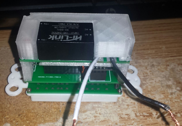
So, I was putting together a couple of my decora wall switches this weekend and was thinking about it's design. When I originally came up with this idea, my plan was to put an outer plastic shell on the whole thing to protect things like the high voltage parts from shorting out on something. The problem I ran into in the final design was that the tolerances of the circuit boards did not allow room for such an outer shell and still have room for it to fit in the wall box. Below is a pic of the power supply board.
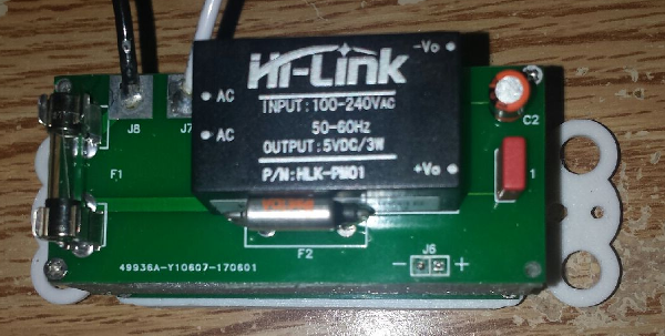
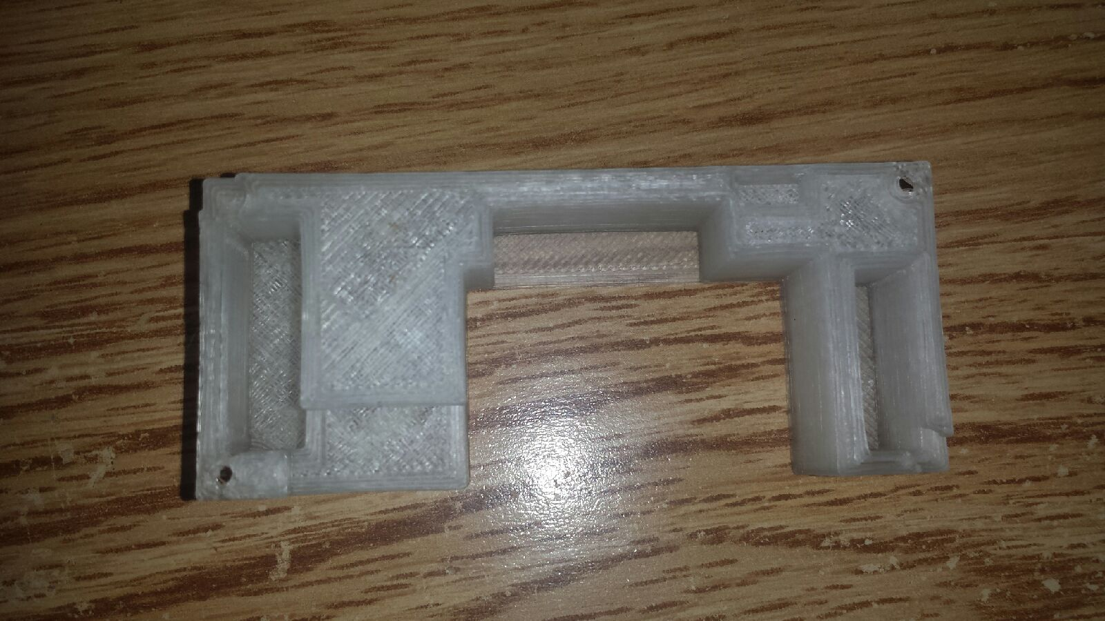
As you can see, there is the standard fuse, the thermal fuse and the J8 connection which expose the hot side of power to the inside of the wall box. If there was a stray ground wire, it could easily touch these and short it out when installing it in the box. So I came up with an alternate idea that kept me within the outer tolerances of the board. Below is the proof of concept design.

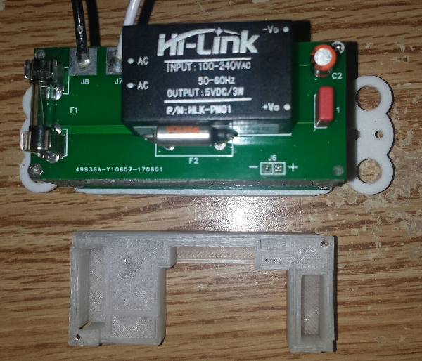
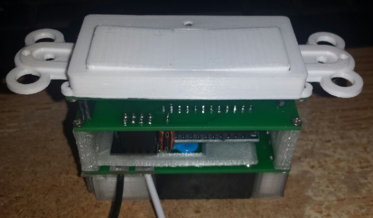
This piece matches the outer dimensions of the circuit board. In two of the corners I have screw holes that match the screw holes in the circuit board. The other two corners just have a relief cut out to allow for the screw heads in those corners. Here they are side by side.
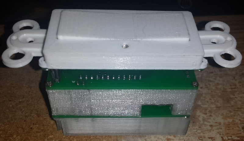
Here are a few more pics showing the part in place. My question is, does anyone see a problem with this type of design?

-
Re: US decora style wall switch
So, I was putting together a couple of my decora wall switches this weekend and was thinking about it's design. When I originally came up with this idea, my plan was to put an outer plastic shell on the whole thing to protect things like the high voltage parts from shorting out on something. The problem I ran into in the final design was that the tolerances of the circuit boards did not allow room for such an outer shell and still have room for it to fit in the wall box. Below is a pic of the power supply board.
As you can see, there is the standard fuse, the thermal fuse and the J8 connection which expose the hot side of power to the inside of the wall box. If there was a stray ground wire, it could easily touch these and short it out when installing it in the box. So I came up with an alternate idea that kept me within the outer tolerances of the board. Below is the proof of concept design.
This piece matches the outer dimensions of the circuit board. In two of the corners I have screw holes that match the screw holes in the circuit board. The other two corners just have a relief cut out to allow for the screw heads in those corners. Here they are side by side.
Here are a few more pics showing the part in place. My question is, does anyone see a problem with this type of design?
@dbemowsk I LOVE!!! this project. I am working on something similar but uses ESP8266. The issue I see with your setup is depth. it just seems way too deep. However I think you can make the width of your board much wider. this would allow you to out more components on a single board.
How are you making a functional rocker for the switch?My project uses the existing switch and GPIO senses state change.
-
@dbemowsk I LOVE!!! this project. I am working on something similar but uses ESP8266. The issue I see with your setup is depth. it just seems way too deep. However I think you can make the width of your board much wider. this would allow you to out more components on a single board.
How are you making a functional rocker for the switch?My project uses the existing switch and GPIO senses state change.
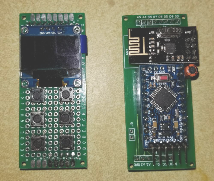
@Jonathan-Roberts thanks. Below is the cad layout of the switch. There are 3 parts, from left to right, the rocker support, the main shell and the button.
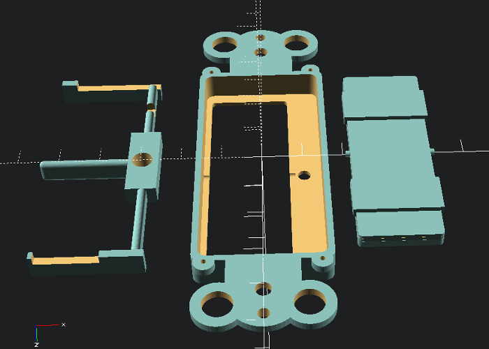
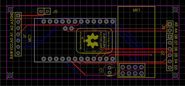
Below are the circuit boards that make up the switch. The left one is the switch board. With that board I can make any one of 3 different switch variations. The single button that you see, a dual button, or a 4 button. There is the option of 1, 2 or 4 LEDs also. The 2 and 4 button switches I have posted on thingiverse. I have not gotten around to posting the single button version there though.
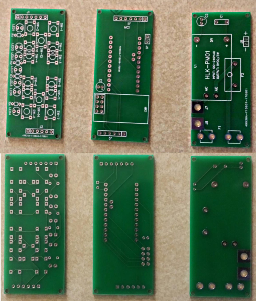
You mention about the depth. From the base of the switch board to the top (bottom) of the HLK power supply is 2 inches (50.8 mm). The ones that I installed today fit inside the box no problem. One of the things that I want to try but haven't yet is to try a different type of header to go from the switch board to the main control/arduino board. shallower headers will decrease the depth. The headers I want to try are a more shallow header. I bought some of these:
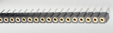
The only problem is that the standard header pins don't fit them. There is another header pin set that mates with these and I haven't gotten around to getting any yet.The nice thing about this setup is that I can remove the switch board and make other sensor boards that mate up with the main board. I have an updated board design that breaks out not only the digital, analog and regulated power lines that this board has, but has pins to connect raw power and I2C if needed. That opens up the possibilities for add on boards that can mount in a standard decora wall plate.
I eventually hope to put these boards on OpenHardware.io, I just haven't had the time to get things ready. These are some of the first switches done with this board design. I had to make a slight change to the power supply board also because I forgot to include the MOV which is the little blue disc under the arduino in the pics in the first post. In the new board design it will get mounted between the HLK and the fuse. I also expanded the pads for the thermal fuse. Once I get things tested better, I will upload the boards.
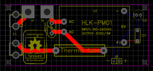
This is the updated main board.
-
@Jonathan-Roberts thanks. Below is the cad layout of the switch. There are 3 parts, from left to right, the rocker support, the main shell and the button.
Below are the circuit boards that make up the switch. The left one is the switch board. With that board I can make any one of 3 different switch variations. The single button that you see, a dual button, or a 4 button. There is the option of 1, 2 or 4 LEDs also. The 2 and 4 button switches I have posted on thingiverse. I have not gotten around to posting the single button version there though.
You mention about the depth. From the base of the switch board to the top (bottom) of the HLK power supply is 2 inches (50.8 mm). The ones that I installed today fit inside the box no problem. One of the things that I want to try but haven't yet is to try a different type of header to go from the switch board to the main control/arduino board. shallower headers will decrease the depth. The headers I want to try are a more shallow header. I bought some of these:
The only problem is that the standard header pins don't fit them. There is another header pin set that mates with these and I haven't gotten around to getting any yet.The nice thing about this setup is that I can remove the switch board and make other sensor boards that mate up with the main board. I have an updated board design that breaks out not only the digital, analog and regulated power lines that this board has, but has pins to connect raw power and I2C if needed. That opens up the possibilities for add on boards that can mount in a standard decora wall plate.
I eventually hope to put these boards on OpenHardware.io, I just haven't had the time to get things ready. These are some of the first switches done with this board design. I had to make a slight change to the power supply board also because I forgot to include the MOV which is the little blue disc under the arduino in the pics in the first post. In the new board design it will get mounted between the HLK and the fuse. I also expanded the pads for the thermal fuse. Once I get things tested better, I will upload the boards.
This is the updated main board.
@dbemowsk - nice work!
As small suggestion would be to move J6 as much towards C1 as possible to increase the gap between DC and AC side.
I would also move down F1 so you can increase the distance between H and N on the AC input. This will increase the creepage between Hot and Neutral (I know the distance for AC in the HLK input is small - but atleast you can do as much as possible on your side). -
looks cool.
regarding the enclosure, i would let more room around the hilink so it can "breath" (for air circulation) -
looks cool.
regarding the enclosure, i would let more room around the hilink so it can "breath" (for air circulation)@sundberg84 said in US decora wall switch continued:
As small suggestion would be to move J6 as much towards C1 as possible to increase the gap between DC and AC side.
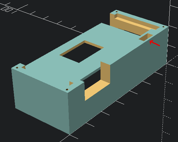
I can do that, it would require a modification of both the power supply and main boards as I would have to move J5 on the main board to match the position of J6. You can't really see it in any of the pics, but here is the cad drawing for the support between the PSU and main board. The rectangular hole wher ethe red arrow is is where the header connectors J5 and J6 go through to connect the DC to the main board. This was meant to help with that separation.
I would also move down F1 so you can increase the distance between H and N on the AC input.
Also a good suggestion. I will put that on as a modification
@scalz said in US decora wall switch continued:
i would let more room around the hilink so it can "breath" (for air circulation)
That was my one concern with the design of that back cover. I do have the thermal fuse, so if it did get too hot, that will blow, but there is not a huge draw on it, so I can't see it getting super hot. It's just the pro mini sitting there waiting for buttons to be pressed. That might be different if I built a different sensor board for the front, but I still can't see a huge draw.
-
I'm not really expert on these safety point :) in general it's better to have minimal vents. Even a small candle can boil your water after hours, it's about heat accumulation.
You'll see by yourself, that's the best test, and i agree maybe you won't have any problem with that ;)
-
@dbemowsk I LOVE!!! this project. I am working on something similar but uses ESP8266. The issue I see with your setup is depth. it just seems way too deep. However I think you can make the width of your board much wider. this would allow you to out more components on a single board.
How are you making a functional rocker for the switch?My project uses the existing switch and GPIO senses state change.
@Jonathan-Roberts You mention about making the board wider. I don't see a lot of point in it with the main board, but with the power supply board I can definitely see an advantage. I have been looking for a way to add at least one relay to that board to make it an actual switch that can control a light or a load. Even a little more width would help in that if I moved the thermal fuse to the other side of the HLK module, that would open up more room on the side where the thermal fuse currently is to put the relay. I will explore that in a future revision. I would then also have to add a control line for the relay that I would naturally add to the current 2 pin header that I use to supply power to the main board.
-
So I finally got around to publishing the first of the boards on the openhardware.io site. It was a bit of work getting things published as I had to post another part of the project on thingiverse. The power supply board is up for review and should be ready soon. I have included the gerber files for Rev 1 of the board for anyone that wants to download them. I have published this under the CERN OHL v1.2 open hardware license . Over the next days I will be publishing the controller board and the switch board. I then hope to design and put out the first revision of my new OLED display board with 6 button keypad which is currently in the prototype stage, but coming along nicely.
-
It was a bit of work, but I was able to get the 3 original boards posted on the openhardware.io site today.
https://www.openhardware.io/view/542/In-wall-scene-controller-multi-switch-board-assembly
https://www.openhardware.io/view/541/In-wall-scene-controller-main-board
https://www.openhardware.io/view/540/In-wall-scene-controller-PSU
Hello! It looks like you're interested in this conversation, but you don't have an account yet.
Getting fed up of having to scroll through the same posts each visit? When you register for an account, you'll always come back to exactly where you were before, and choose to be notified of new replies (either via email, or push notification). You'll also be able to save bookmarks and upvote posts to show your appreciation to other community members.
With your input, this post could be even better 💗
Register Login