Skip to content
  • MySensors
  • OpenHardware.io
  • Categories
  • Recent
  • Tags
  • Popular
Skins
  • Light
  • Brite
  • Cerulean
  • Cosmo
  • Flatly
  • Journal
  • Litera
  • Lumen
  • Lux
  • Materia
  • Minty
  • Morph
  • Pulse
  • Sandstone
  • Simplex
  • Sketchy
  • Spacelab
  • United
  • Yeti
  • Zephyr
  • Dark
  • Cyborg
  • Darkly
  • Quartz
  • Slate
  • Solar
  • Superhero
  • Vapor

  • Default (No Skin)
  • No Skin
Collapse
Brand Logo
ferpandoF

ferpando

@ferpando
Hero Member
About
Posts
171
Topics
27
Shares
0
Groups
1
Followers
1
Following
0

Posts

Recent Best Controversial

  • 6 Way wall touch switch
    ferpandoF ferpando

    Hello,

    This weekend I've been busy with a prototype for a touch wall switch.
    So far is going pretty well and everything seems to work.
    I still need to integrate it with MySensors, but I hope this will be the easiest part.
    The only problem I found is with the sensitivity of the touch sensors when connected to external power.
    It works perfectly when using USB power, but not quite right then using AC power.

    Here's how it looks so far. Remember this is just a proof of concept and many things where just do as I go and probably will be a better way to do it.

    Any suggestions / comments will be greatly appreciated.

    This is the front plate made with a 2mm methacrylate plastic, with a printed paper behind.
    c100.jpg

    This is the back side with the touch controller
    c100-5.jpg

    And this is the actual node with the led driver and the buzzer
    c100-6.jpg

    And this is how it works for now
    c100b.mp4

    My Project

  • Motion and lux meters combined in a single device
    ferpandoF ferpando

    Hello,

    I always wanted a motion sensor that could also detect light levels.
    Until now I used two sensors attached to one arduino to achieve that, but now I make a hardware combination that works and also looks more discreet.

    This is the device I used as a base, adding the light sensor.

    _DSC8283.jpg

    First of all I removed the white dome.
    Then a little adjustment was needed becasue the light sensor is too long so the sensor chip fits properly inside the dome.

    _DSC8284.jpg

    Also the white plastic needed some cutting to allow the circuit to enter the dome.

    _DSC8285.jpg

    The light sensor circuit has to be on the opposite side of this little metal pit in order to fit properly.

    _DSC8286.jpg

    Here is the assembly almos done, with the light sensing chip facing up inside the dome.

    _DSC8287.jpg

    Little hotglue on the corners to hold it toghether

    _DSC8290.jpg

    And that's all to it.

    _DSC8291.jpg

    Here's the code. Just a simple combine of the 2 sensors.

    #include <MySensor.h>  
    #include <SPI.h>
    #include <BH1750.h>
    #include <Wire.h> 
    
    #define CHILD_ID_LIGHT 0
    #define LIGHT_SENSOR_ANALOG_PIN 0
    unsigned long SLEEP_TIME = 30000; // Sleep time between reads (in milliseconds)
    
    #define DIGITAL_INPUT_SENSOR 3   // The digital input you attached your motion sensor.  (Only 2 and 3 generates interrupt!)
    #define INTERRUPT DIGITAL_INPUT_SENSOR-2 // Usually the interrupt = pin -2 (on uno/nano anyway)
    #define CHILD_ID 1   // Id of the sensor child
    
    BH1750 lightSensor;
    
    MySensor gw;
    // Initialize motion message
    MyMessage msg(CHILD_ID, V_TRIPPED);
    MyMessage msg2(CHILD_ID_LIGHT, V_LIGHT_LEVEL);
    uint16_t lastlux;
    
    void setup()  
    {  
      gw.begin();
    
      // Send the sketch version information to the gateway and Controller
      gw.sendSketchInfo("MotionLuxSensor", "1.0");
    
      pinMode(DIGITAL_INPUT_SENSOR, INPUT);      // sets the motion sensor digital pin as input
    
      // Register all sensors to gw (they will be created as child devices)
      gw.present(CHILD_ID, S_MOTION);
      gw.present(CHILD_ID_LIGHT, S_LIGHT_LEVEL);
    
      lightSensor.begin();
    }
    
    void loop()     
    {     
      // Read digital motion value
      boolean tripped = digitalRead(DIGITAL_INPUT_SENSOR) == HIGH; 
        
      Serial.println(tripped);
      gw.send(msg.set(tripped?"1":"0"));  // Send tripped value to gw 
    
      uint16_t lux = lightSensor.readLightLevel();// Get Lux value
      Serial.println(lux);
      if (lux != lastlux) {
          gw.send(msg2.set(lux));
          lastlux = lux;
      }
    
    
      // Sleep until interrupt comes in on motion sensor. Send update every two minute. 
      gw.sleep(INTERRUPT,CHANGE, SLEEP_TIME);
    }
    
    Hardware

  • 6 Way wall touch switch
    ferpandoF ferpando

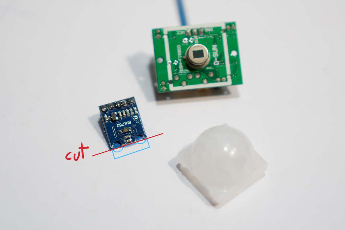
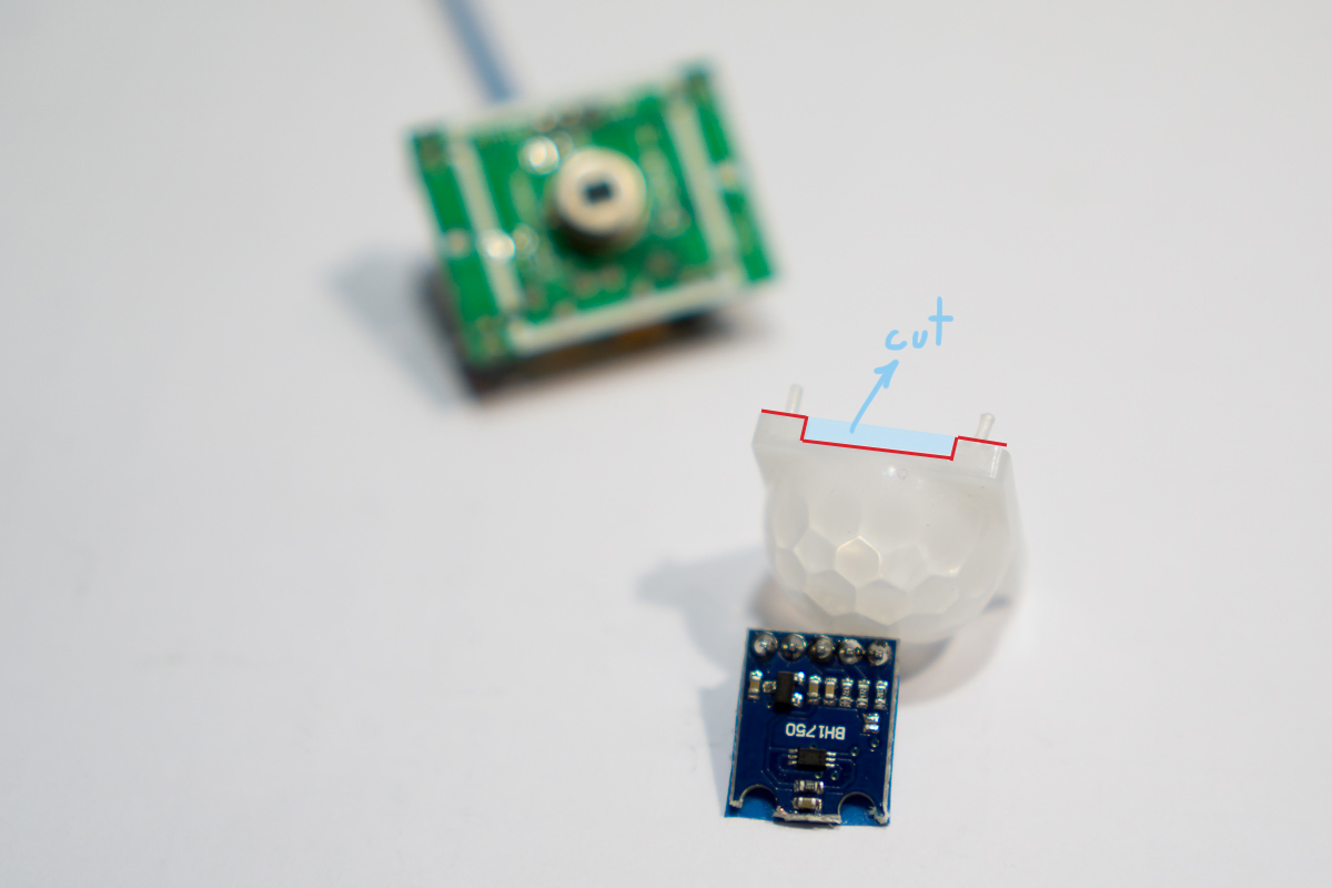
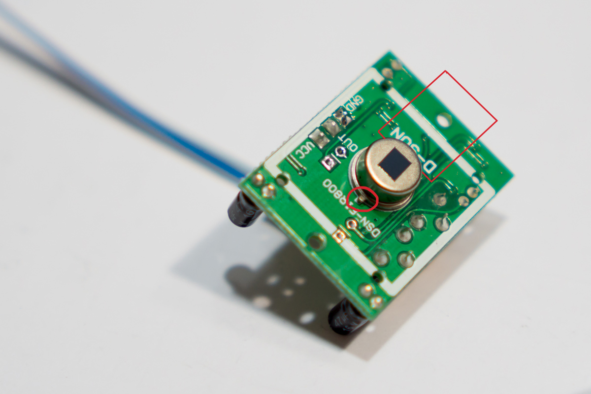
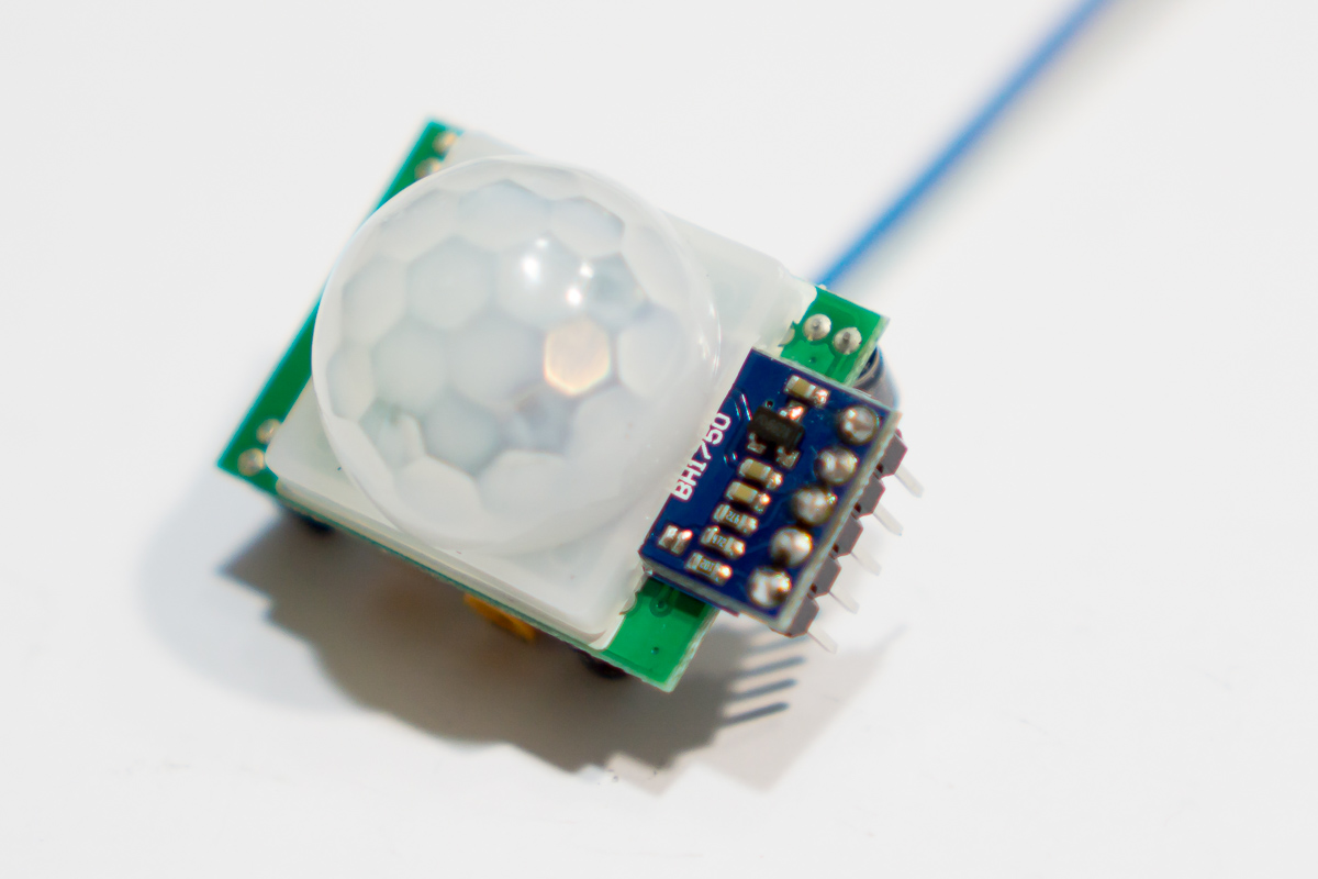
    This is a rough integration of the code with MySensors.
    It sends messages back and forth, so if a button is touched it turns on the corresponding device on the controller and if the switch is turned on the controller, the touch leds are updated accordingly

    #include "mpr121.h"
    #include <Wire.h>
    #include "LedControlMS.h"
    #include <MySensor.h>
    #include <SPI.h>
    #include <MyBuffer.h>
    
    #define CHILD_ID1 1   // first child
    #define CHILD_NUM 6    // number of switches
    
    
    //define working pins
     #define BUZZER 7   // buzzer pin
     #define DIN    6   // pin 6 is connected to the DataIn 
     #define CLK    4   // pin 4 is connected to the CLK 
     #define LOD    8   // pin 8 is connected to LOAD 
     #define IRQ    3   // irq pin for touch control
     #define BAKLIT 5   // pin PWM for backlight leds
     
    // ********* MyBuffer ***********************************************************
    MyBuffer buffer;               // define a new buffer
    long previousMillis = 0;       // will store last time buffer was processed
    long interval = 1000;           // interval at which to check buffer
    // ******************************************************************************
    
    MySensor gw;
    
    //define a new led control
    LedControl lc=LedControl(DIN,CLK,LOD,1);
    
    //int irqpin = 3;  // Digital pin IRQ
    boolean touchStates[12]; //to keep track of the previous touch states
    boolean touchMemory[12]; //to keep track of the touch switch states
    
    // correspondence between touch and led pins
    int mapping[2][6]={{0,1,2,3,4,5}     // touch pins
                      ,{1,0,2,5,4,3}};   // led pins
    
    int sound = 500;
    int touchDelay=500;
    
    void setup(){
      // init LED backlight
      pinMode(BAKLIT, OUTPUT);
      analogWrite(BAKLIT, 5);
      
      pinMode(IRQ, INPUT);
      digitalWrite(IRQ, HIGH); //enable pullup resistor
      Wire.begin();
      pinMode(BUZZER, OUTPUT);
      
      for (int i=0; i < 12; i++){
        touchMemory[i]=false;
      }
      mpr121_setup();
      
      //initialize MAX72XX
      lc.shutdown(0,false);
      lc.setIntensity(0,15);
      lc.clearDisplay(0);
      
      gw.begin(incomingMessage, AUTO); //do not make relay node
      gw.sendSketchInfo("WallTouch", "1.0");
      for (int i=0; i<CHILD_NUM;i++) {
       
        gw.present(CHILD_ID1+i, S_LIGHT);
        
        // Set touch button leds to last known state (using eeprom storage) 
        touchMemory[i] = gw.loadState(i)?true:false;
        setLed(mapping[1][i],touchMemory[i]);
      }
    }
    
    void loop(){
      gw.process();
      //watch for touch events
      readTouchInputs();
      //check for buffer items once in a while
      checkTime();
    }
    
    void checkTime(){
       unsigned long currentMillis = millis();
       if(currentMillis - previousMillis > interval) {
            previousMillis = currentMillis;  
            processBuffer();    
          }
    }
    
    void incomingMessage(const MyMessage &message) {
      buffer.push(message.sensor,message.type,message.getString());
    }
    
    //gets message from buffer if exists
    void processBuffer(){
        if(!buffer.isEmpty()){
            String msg=buffer.pop();
            
            int mIndex = msg.indexOf(';');
            int secondmIndex = msg.indexOf(';', mIndex+1);
      
            String firstValue = msg.substring(0, mIndex);
            String secondValue = msg.substring(mIndex+1, secondmIndex);
            String thirdValue = msg.substring(secondmIndex+1);
            
            int sensor = firstValue.toInt();
            int type = secondValue.toInt();
            String data = thirdValue;
      
            Serial.println("    >> Process MSG: s:"+ firstValue +", t:"+secondValue+", d:"+thirdValue);
            
            processMsg(sensor, type, data);
        }
    }
    
    //process message from queue
    void processMsg(int sensor, int type, String data){
      boolean msg;
       switch(type){
            case V_LIGHT: 
               //comando para 1 rele
               
               msg=data.toInt()?1:0;
               // Store state in eeprom
               gw.saveState(sensor, msg);      
               // Write some debug info
               Serial.print("--> Incoming change for child:");
               Serial.print(sensor-1);
               Serial.print(", New status: ");
               Serial.println(msg);
               setTouchButton(sensor-1);
              break;
    
          }
    }
    
    void setTouchButton(int pressed){
          MyMessage msg(CHILD_ID1+pressed,V_LIGHT);
          
          Serial.print("pin ");
          Serial.print(pressed);
          Serial.print(" was just touched");
          Serial.print(", turning: ");
          touchMemory[pressed]=touchMemory[pressed]?false:true;
          gw.saveState(pressed, touchMemory[pressed]);
          Serial.println(touchMemory[pressed]?"ON":"OFF");
          setLed(mapping[1][pressed],touchMemory[pressed]?true:false);
      
          gw.send(msg.set(touchMemory[pressed] ? 1 : 0));
          touchSound();
    }
    
    void setLed(int led, boolean lit){
      lc.setLed(0,0,led,lit);
    }
    
    void readTouchInputs(){
      if(!checkInterrupt()){
        
        //read the touch state from the MPR121
        Wire.requestFrom(0x5A,2); 
        
        byte LSB = Wire.read();
        byte MSB = Wire.read();
        
        uint16_t touched = ((MSB << 8) | LSB); //16bits that make up the touch states
    
        
        for (int i=0; i < 12; i++){  // Check what electrodes were pressed
          if(touched & (1<<i)){
          
            if(touchStates[i] == 0){
               //pin i was just touched
              setTouchButton(i);  
              delay(touchDelay);
              }else if(touchStates[i] == 1){
                //pin i is still being touched
              }  
          
            touchStates[i] = 1;      
          }else{
           /* if(touchStates[i] == 1){
              Serial.print("pin ");
              Serial.print(i);
            Serial.println(" is no longer being touched");
              
              //pin i is no longer being touched
           }*/
            
            touchStates[i] = 0;
          }
        
        }
      }
    }
    
    void touchSound(){
      tone(BUZZER, sound, 3);
    }
    
    
    void mpr121_setup(void){
    
      set_register(0x5A, ELE_CFG, 0x00); 
      
      // Section A - Controls filtering when data is > baseline.
      set_register(0x5A, MHD_R, 0x01);
      set_register(0x5A, NHD_R, 0x01);
      set_register(0x5A, NCL_R, 0x00);
      set_register(0x5A, FDL_R, 0x00);
    
      // Section B - Controls filtering when data is < baseline.
      set_register(0x5A, MHD_F, 0x01);
      set_register(0x5A, NHD_F, 0x01);
      set_register(0x5A, NCL_F, 0xFF);
      set_register(0x5A, FDL_F, 0x02);
      
      // Section C - Sets touch and release thresholds for each electrode
      set_register(0x5A, ELE0_T, TOU_THRESH);
      set_register(0x5A, ELE0_R, REL_THRESH);
     
      set_register(0x5A, ELE1_T, TOU_THRESH);
      set_register(0x5A, ELE1_R, REL_THRESH);
      
      set_register(0x5A, ELE2_T, TOU_THRESH);
      set_register(0x5A, ELE2_R, REL_THRESH);
      
      set_register(0x5A, ELE3_T, TOU_THRESH);
      set_register(0x5A, ELE3_R, REL_THRESH);
      
      set_register(0x5A, ELE4_T, TOU_THRESH);
      set_register(0x5A, ELE4_R, REL_THRESH);
      
      set_register(0x5A, ELE5_T, TOU_THRESH);
      set_register(0x5A, ELE5_R, REL_THRESH);
      /*
      set_register(0x5A, ELE6_T, TOU_THRESH);
      set_register(0x5A, ELE6_R, REL_THRESH);
      
      set_register(0x5A, ELE7_T, TOU_THRESH);
      set_register(0x5A, ELE7_R, REL_THRESH);
      
      set_register(0x5A, ELE8_T, TOU_THRESH);
      set_register(0x5A, ELE8_R, REL_THRESH);
      
      set_register(0x5A, ELE9_T, TOU_THRESH);
      set_register(0x5A, ELE9_R, REL_THRESH);
      
      set_register(0x5A, ELE10_T, TOU_THRESH);
      set_register(0x5A, ELE10_R, REL_THRESH);
      
      set_register(0x5A, ELE11_T, TOU_THRESH);
      set_register(0x5A, ELE11_R, REL_THRESH);
      */
      // Section D
      // Set the Filter Configuration
      // Set ESI2
     set_register(0x5A, FIL_CFG, 0x12);  //12 mas  menos
      
       //set_register(0x5A, FIL_CFG, 0x24);  //segundo filtro
     // set_register(0x5A, 0x5C, 0x28);    // primer filtro (mio)
      //ajuste de la corrente de carga de cada pin
       /*  set_register(0x5A, 0x5F, CDC_sensor[0]);   //el 0
          set_register(0x5A, 0x60, CDC_sensor[1]);   //el 1
          set_register(0x5A, 0x61, CDC_sensor[2]);   //el 2
          set_register(0x5A, 0x62, CDC_sensor[3]);   //el 3
          set_register(0x5A, 0x63, CDC_sensor[4]);   //el 4
          set_register(0x5A, 0x64, CDC_sensor[5]);   //el 5
      */
      
      
      // Section E
      // Electrode Configuration
      // Set ELE_CFG to 0x00 to return to standby mode
      set_register(0x5A, ELE_CFG, 0x0C);  // Enables all 12 Electrodes
      
      
      // Section F
      // Enable Auto Config and auto Reconfig
      /*set_register(0x5A, ATO_CFG0, 0x0B);
      set_register(0x5A, ATO_CFGU, 0xC9);  // USL = (Vdd-0.7)/vdd*256 = 0xC9 @3.3V   set_register(0x5A, ATO_CFGL, 0x82);  // LSL = 0.65*USL = 0x82 @3.3V
      set_register(0x5A, ATO_CFGT, 0xB5);*/  // Target = 0.9*USL = 0xB5 @3.3V
      
      set_register(0x5A, ELE_CFG, 0x0C);
      
    }
    
    
    boolean checkInterrupt(void){
      return digitalRead(IRQ);
    }
    
    
    void set_register(int address, unsigned char r, unsigned char v){
        Wire.beginTransmission(address);
        Wire.write(r);
        Wire.write(v);
        Wire.endTransmission();
    }
    
    My Project

  • PCB design and production
    ferpandoF ferpando

    Here is my first attemp at it.
    I just started with eagle, so maybe there is room for improvement.
    This is for a dimmer node, with some connector for motion detector and light sensor.
    It has an onboard 7805 regulator and a mosfet to PWM the leds.

    mynode.png

    Comments are welcome

    Hardware pcb production design

  • 6 Way wall touch switch
    ferpandoF ferpando

    I got it finally installed.
    This is what it looks like.

    https://youtu.be/2AEMxA0ZxUc

    I'm working on a pcb smaller version. I'll keep you posted.

    My Project

  • Nap machine / Scene controller
    ferpandoF ferpando

    Hello,

    It's been a while since a posted last. It's been really busy around here.

    I've been using a node with a button to start and stop nap time, and control some scene.

    My controller has been Vera for a long time, but now I think it's time for an upgrade.
    I installed openhab a few weeks back and started to play with it.

    Anyway, I thought it was time to make a new thing to control naps. That's how nap machine was born. But as I was building it, I thought it could do a lot more. Become a grown up scene controller.

    As you can see in the video, it has an oled display, a rotary encoder and a buzzer.
    It works with SPI displays, as well as I2C. It also has a radio to connect with MySensors gateway.
    The rotary encoder has a integrated button and 2 leds. The program can detect rotation, single click, double click and long click.

    Take a look at the video to see some options. Still in early stage, but it works and it's fully integrated with MySensors.
    I need now to integrate it with openhab, and in this regard I hope to find some help here.

    Feel free to comment or suggest new uses.
    In the following days I'll post the code as it is now, and some schematics for those interested.

    VIDEO:
    napMachine
    0_1504390432905_Captura de pantalla 2017-09-03 a las 0.13.12.png

    My Project

  • Using optocoupler as actuator in node
    ferpandoF ferpando

    @BulldogLowell
    I'm using 74HC595.
    I solved it changing the sketch from relay to servo, and them making some modifications to it.
    It works very nice now.

    Hardware

  • Node freezing up
    ferpandoF ferpando

    Hello,

    I have a node that every once in a while just stops responding.
    I have to unplug it to get it back working.
    It is strange because it doesn't appear to be a reason.
    Anyone had issues like this before?

    Troubleshooting

  • 6 Way wall touch switch
    ferpandoF ferpando

    @Atman
    Yes it is all hand made.
    Next step would be to make a board to make it smaller and easier to make

    My Project

  • Scene too fast for gateway?
    ferpandoF ferpando

    @hek
    Here's a basic implementation of the sending queue I came up with.

    First I modified this functions:

    function sendCommandWithMessageType(altid, messageType, ack, variableId, value)
    
    	local cmd = altid..";".. msgType[messageType] .. ";" .. ack .. ";" .. variableId .. ";" .. value
    
    	-- only add to list if of SET type
    	if (messageType =="SET") then
    		addToMyQueue(cmd)
     	end
    
    	if (luup.io.write(cmd) == false)  then
    		task("Cannot send command - communications error", TASK_ERROR)
    		luup.set_failure(true)
    		return false
    	end
    
    	return true
    end
    
    function processIncoming(s)
    	local incomingData = s:split(";")
    	if (#incomingData >=4) then
    		-- check if msg is in the list to remove it
    		checkMyQueue(s);
    
    		local nodeId = incomingData[1]
    
    ...
    
    end
    

    And added this other functions:

    -- adds cmd msg to the list before sending
    function addToMyQueue(myCmd)
    
    	local isFound = inTable(MyMsgs, myCmd);
    	-- if not already in the list, add it
    	if (isFound == false) then
    		table.insert( MyMsgs, myCmd )
    	end
    	
    end
    
    -- check if msg is in the list to remove it
    function checkMyQueue(msg)
    	log(MyPrefix .. ">T> queue        : " .. printTable(MyMsgs) )
    	local isFound = inTable(MyMsgs, msg);
    	-- if msg found, remove it because has been executed
    	if (isFound ~= false) then
    		log("msg found in pos: "..isFound..". Removing from list...")
    		table.remove (MyMsgs , isFound) 
    		else
    
    			log("msg not found in list") 
    		end
    	log(MyPrefix .. ">T> queue updated: " .. printTable(MyMsgs) )
    end
    
    function inTable(tbl, item)
        for key, value in pairs(tbl) do
            if value == item then return key end
        end
        return false
    end
    

    It basically works but the problem with this is that processIncoming() is only processed when a new message arrives, so there is no way we could re-send lost messages when iddle.

    We need a function that could be executed at regular intervals to check if there are any messages left in the queue to be re-send.

    Vera

  • 16 relay with arduino. Change many at the same time
    ferpandoF ferpando

    I'm working on a node with 16 relays controlled by Vera.
    I use shift registers and opto couplers to connect the relays to the arduino board. This is system is apparently a bit slow, so if you try to change a few of the relays at the same time, most of them will fail.

    I've been working on a solution adding a buffer to the system, both at Vera's end and node end. If you are interested, you can read about it here:

    http://forum.mysensors.org/topic/131/scene-too-fast-for-gateway/4

    What come next is a addition to that system.
    This sketch allows to operate the relays as before (1 relay at a time), but also allows to receive a message that changes many or all o f the relays at the same time, with only one message sent by Vera.

    First of all I created a function in the startup Lua to make it easier to send messages to the node.

    -- send to multiple relays Mysensor.org
    function updateRelays(parent, child, msg)
        local newRadioId=tostring(child)..";100"
        luup.call_action("urn:upnp-arduino-cc:serviceId:arduino1", "SendCommand",
        {radioId=newRadioId, variableId="LIGHT", value=msg}, parent)
        end
    

    Then I use this code to send the message from a scene or Pleg

    -- order: (first......last)
    -- 1: relay ON, 0: relay OFF
    -- guide       1234567812345678
    local relays="b1100100000000100"
    updateRelays(130, 3, relays)
    

    In my case, 130 is the parent node id, 3 is the relay node id, and relays contains a binary representation of every relay, 1 mening ON and 0 meaning OFF.

    This is all you need to do to turn a buch of the relays in any way you need, all at the same time. The rest is taken care by the sketch (decoding the binary message, sending back the ack's to the gw, etc)

    
    // This  will remember relay state even after power failure.
    
    
    #include <MySensor.h>
    #include <SPI.h>
    #include <MyBuffer.h>
    
    #define RELAY_1  0  // number for first relay (second on pin+1 etc)
    #define NUMBER_OF_RELAYS 16 // Total number of attached relays
    #define RELAY_ON HIGH  // GPIO value to write to turn on attached relay
    #define RELAY_OFF LOW // GPIO value to write to turn off attached relay
    
    int dataPin  = 6;//11;        //Define which pins will be used for the Shift Register control
    int latchPin = 4;//8;
    int clockPin = 7;//12;
    
    boolean registers[16];//={HIGH,HIGH,HIGH,HIGH,HIGH,HIGH,HIGH,HIGH,HIGH,HIGH,HIGH,HIGH,HIGH,HIGH,HIGH,HIGH};
    
    long previousMillis = 0;        // will store last time buffer was processed
    long interval = 1000;           // interval at which to check buffer
    
    MyBuffer buffer;                // define a new buffer
    MySensor gw;
    MyMessage msgRelay(0,V_LIGHT);  //message for akc multiple relays back to gw
    
    void setup()  
    {   
        // Then set relay pins in output mode 
        pinMode(dataPin, OUTPUT); 
        pinMode(latchPin, OUTPUT);
        pinMode(clockPin, OUTPUT);
        
        writeReg(false); //reset all relays to off at boot
        
        // Initialize library and add callback for incoming messages
        gw.begin(incomingMessage, AUTO);
        
        // Send the sketch version information to the gateway and Controller
        gw.sendSketchInfo("HomeRelay_1", "1.1");
        
        //loop through the relays
        for (int sensor=RELAY_1; sensor<NUMBER_OF_RELAYS; sensor++) 
            {
            // Register all sensors to gw (they will be created as child devices)
            gw.present(sensor, S_LIGHT);
         
            // Set relays array to last known state (using eeprom storage) 
            registers[sensor] = gw.loadState(sensor)?RELAY_ON:RELAY_OFF;
            }
    
        //set relays
        writeReg(true);
    }
    
    
    void loop() 
    {
      // Alway process incoming messages whenever possible
      gw.process();
      
      //check for buffer items one in a while
      checkTime();
    }
    
    void incomingMessage(const MyMessage &message) {
      buffer.push(message.sensor,message.type,message.getString());
    }
    
    void checkTime(){
       unsigned long currentMillis = millis();
       if(currentMillis - previousMillis > interval) {
            previousMillis = currentMillis;  
            processBuffer();    
          }
    }
    
    //gets message from buffer if exists
    void processBuffer(){
        if(!buffer.isEmpty()){
            String msg=buffer.pop();
            
            int mIndex = msg.indexOf(';');
            int secondmIndex = msg.indexOf(';', mIndex+1);
      
            String firstValue = msg.substring(0, mIndex);
            String secondValue = msg.substring(mIndex+1, secondmIndex);
            String thirdValue = msg.substring(secondmIndex+1);
            
            int sensor = firstValue.toInt();
            int type = secondValue.toInt();
            String data = thirdValue;
      
            Serial.println("    >> Process MSG: s:"+ firstValue +", t:"+secondValue+", d:"+thirdValue);
            
            processMsg(sensor, type, data);
        }
    }
    
    void processMsg(int sensor, int type, String data){
         boolean msg;
    
        // We only expect one type of message from controller. But we better check anyway.
        if (type==V_LIGHT) {
       
           if(sensor==100){ //command for all relays
            for (int i = 16; i>=1; i--)
                {
                
                msg=data.substring(i,i+1).toInt()?RELAY_OFF:RELAY_ON;
               
                registers[i-1]=msg;
                gw.saveState(i-1, msg);
                
                //send message back to gw to change child devices accordingly
                gw.send(msgRelay.setSensor(i-1).set(msg?RELAY_OFF:RELAY_ON));
                }
           }else{ //command for one relay
               //my relays need LOW to activate. Others might be different
               msg=data.toInt()?RELAY_OFF:RELAY_ON;
               
               registers[sensor]=msg;
             
               // Store state in eeprom
               gw.saveState(sensor, msg);
               }
    
           //set relays
           writeReg(true);
         } 
    }
    
    void writeReg(boolean rst){
      int loc_reg;
      digitalWrite(latchPin, LOW);
      for (int i = 15; i>=0; i--)
        {
        loc_reg=rst?registers[i]:HIGH;
        digitalWrite(clockPin, LOW);
        digitalWrite(dataPin, loc_reg );
        digitalWrite(clockPin, HIGH);
        }
      digitalWrite(latchPin, HIGH);
    
    }
    
    
    Development

  • 6 Way wall touch switch
    ferpandoF ferpando

    @korttoma
    Yes that's the module.
    Maybe i should use just the chip in next versions to integrate better with the rest so the final board could be smaller

    My Project

  • Scene too fast for gateway?
    ferpandoF ferpando

    @hek
    I got the timer working with this help:

    http://forum.micasaverde.com/index.php?topic=10258.0

    I'll implement it and see what happens

    Vera

  • Dimmable led actuator sketch enhancement
    ferpandoF ferpando

    Hello,

    I've been working on a simple mod of the dimmable led actuator available in the examples folder.

    I needed a few things that were not included, like the ability to set a more precise fade level, make longer fades and also being able to change those fade times dynamically.

    Also, as a result of longer dafe times, I had to modify the sketch so the node is still able to send/receive messages during fade time.

    You could send messages from VERA this way:

    luup.call_action("urn:upnp-arduino-cc:serviceId:arduino1", "SendCommand", {radioId="6;100", variableId="DIMMER", value="100,25"}, 130)
    

    This message is sent to node id 6, with parent node id 130, and tells the node to fade to 100% in 25 seconds.
    You could choose any number (0-100) to fade to, instead of the 10% increment Vera offers. Also the old functionality remains working as before.

    Here's the sketch in case someone is interested:

    /***
     * This program is free software; you can redistribute it and/or
     * modify it under the terms of the GNU General Public License
     * version 2 as published by the Free Software Foundation.
     * 
     * DESCRIPTION
     * This sketch provides a Dimmable LED Light using PWM and based Henrik Ekblad 
     * <henrik.ekblad@gmail.com> Vera Arduino Sensor project.  
     * Developed by Bruce Lacey, inspired by Hek's MySensor's example sketches.
     * 
     * The circuit uses a MOSFET for Pulse-Wave-Modulation to dim the attached LED or LED strip.  
     * The MOSFET Gate pin is connected to Arduino pin 3 (LED_PIN), the MOSFET Drain pin is connected
     * to the LED negative terminal and the MOSFET Source pin is connected to ground.  
     *
     * This sketch is extensible to support more than one MOSFET/PWM dimmer per circuit.
     *
     * REVISION HISTORY
     * Version 1.0 - February 15, 2014 - Bruce Lacey
     * Version 1.1 - August 13, 2014 - Converted to 1.4 (hek) 
     * Version 1.2 - April 13, 2015 - Added long dynamic and precise fade, also made fade non exclusive (ferpando)
     ***/
     
     #include <Time.h> 
     
    #define SN "DimmableLED"
    #define SV "1.2"
    
    #include <MySensor.h> 
    #include <SPI.h>
    
    #define LED_PIN 5      // Arduino pin attached to MOSFET Gate pin
    
    MySensor gw(9,10);
    
    static int currentLevel = 0;  // Current dim level...
    static int requestedLevel = 0;
    
    MyMessage dimmerMsg(0, V_DIMMER);
    MyMessage lightMsg(0, V_LIGHT);
    
    int FADE_DELAY;   // Delay in ms for each percentage fade up/down (10ms = 1s full-range dim)
    
    /***
     * Dimmable LED initialization method
     */
    void setup()  
    { 
      Serial.println( SN ); 
      gw.begin( incomingMessage );
      
      // Register the LED Dimmable Light with the gateway
      gw.present( 0, S_DIMMER );
      
      gw.sendSketchInfo(SN, SV);
      // Pull the gateway's current dim level - restore light level upon sendor node power-up
      gw.request( 0, V_DIMMER );
    
    }
    
    /***
     *  Dimmable LED main processing loop 
     */
    void loop() 
    {
      gw.process();
      fadeToLevel();
      // if delay is too long, it might stop the node from receiving/sending more messages for a long time.
      //doing it this way, the node can keep functioning regardless fade completition.
    }
    
    void incomingMessage(const MyMessage &message) {
      if (message.type == V_LIGHT || message.type == V_DIMMER) {
        
        if(message.sensor == 100 ){ //fade special, addressed to node 100
          // Message payload: value to fade to, seconds to fade     example: "20,10"
          
          int commaIndex = msg.indexOf(',');
    
          String firstValue = msg.substring(0, commaIndex);
          String secondValue = msg.substring(commaIndex+1);
    
          requestedLevel=firstValue.toInt();
          int steps=abs(currentLevel-requestedLevel);
    
          if(commaIndex == -1){
             FADE_DELAY=10;
          }else { 
             FADE_DELAY = 1000* secondValue.toInt() / steps;
          }
        }else { //fade normal
        
              FADE_DELAY=10;
              //  Retrieve the power or dim level from the incoming request message
              requestedLevel = atoi( message.data );
              
              // Adjust incoming level if this is a V_LIGHT variable update [0 == off, 1 == on]
              requestedLevel *= ( message.type == V_LIGHT ? 100 : 1 );
              
              // Clip incoming level to valid range of 0 to 100
              requestedLevel = requestedLevel > 100 ? 100 : requestedLevel;
              requestedLevel = requestedLevel < 0   ? 0   : requestedLevel;
              
              }
           
          Serial.print( "Changing level to " );
          Serial.print( requestedLevel );
          Serial.print( ", from " ); 
          Serial.println( currentLevel ); 
           
             
          // Inform the gateway of the current DimmableLED's SwitchPower1 and LoadLevelStatus value...
          gw.send(lightMsg.set(currentLevel > 0 ? 1 : 0));
      
          // hek comment: Is this really nessesary?
          gw.send( dimmerMsg.set(currentLevel) );
        
        }
    }
    
    /***
     *  This method provides a graceful fade up/down effect
     */
    void fadeToLevel() {
    
      if ( currentLevel != requestedLevel ) {
        int delta = ( requestedLevel - currentLevel ) < 0 ? -1 : 1;
      
        currentLevel += delta;
        Serial.print( "analog write: " );
        Serial.println( currentLevel / 100. * 255 );
        analogWrite( LED_PIN, (int)(currentLevel / 100. * 255) );
        delay( FADE_DELAY );
      }
      
    }
    
    Development

  • 6 Way wall touch switch
    ferpandoF ferpando

    @Vince
    I left some light in the leds because when it's dark/night, you can still find the buttons.
    Now it has 2 leds per button, but the plan is to use an RGB led so it can be further customized.

    My Project

  • Scene too fast for gateway?
    ferpandoF ferpando

    @hek
    I've been trying to get some buttons in the vera plugin but I've had not much luck.
    I addded some code to arduino.xml and arduino.json but nothing appears.
    I uploaded the files to the repo. Could you take a look when you have the time?

    S_Arduino.xml
    D_Arduino1.json
    L_Arduino.lua

    Yesterday I also made a new system for the nodes to have also a queue.
    Looks something like this:

    
    #include <MySensor.h>
    #include <SPI.h>
    #include <MyBuffer.h>
    
    .......
    
    long previousMillis = 0;       // will store last time buffer was processed
    long interval = 1000;           // interval at which to check buffer
    MyBuffer buffer;               // define a new buffer
    MySensor gw;
    
    ..........
    void setup() {  .... sensor setup code....  }
    
    void loop() 
    { 
      gw.process();
            
      unsigned long currentMillis = millis();
      if(currentMillis - previousMillis > interval) {
            previousMillis = currentMillis;  
            processBuffer();    
          }
    } 
    
    void incomingMessage(const MyMessage &message) {
        buffer.push(message.sensor,message.type);
    }
    
    //gets message from buffer if exists
    void processBuffer(){
    if(!buffer.isEmpty()){
          String msg=buffer.pop();
          
          int mIndex = msg.indexOf(';');
          int secondmIndex = msg.indexOf(';,', mIndex+1);
    
          String firstValue = msg.substring(0, mIndex);
          String secondValue = msg.substring(mIndex+1, secondmIndex);
          
          int sensor = firstValue.toInt();
          int type = secondValue.toInt();
       
          processMsg(sensor, type);
      }
    }
    
    //process message from queue
    void processMsg(int sensor, int type){
         //do some stuff
    }
    

    It's pretty basic but it works.
    The library files are here:

    MyBuffer.h
    MyBuffer.cpp

    Vera
  • Login

  • Don't have an account? Register

  • Login or register to search.
  • First post
    Last post
0
  • MySensors
  • OpenHardware.io
  • Categories
  • Recent
  • Tags
  • Popular