could you share a circuit diagram? thanks
Posts made by jumping
-
RE: Temp, pressure, humidity + OLED
@skysonic said in Temp, pressure, humidity + OLED:
Great project
what sketch have you used?
i am very interested to make a temprature switch for my kitchen with that kind of display
great workthank you! My sketch is based on bme280 temp, hum, pressure sketch plus the oled display. bye
-
RE: New 2.2.0 Signal report function
thanks, next time I will use the github search function
-
RE: New 2.2.0 Signal report function
@mfalkvidd thanks for your answer, can you tell me what is the RF24_getSendingRSSI?
int16_t transportGetSendingRSSI(void) { return RF24_getSendingRSSI(); }
-
RE: New 2.2.0 Signal report function
Hi,
the NRF24l01 doesn't have a RSSI function as reported in Nordic datasheet, so how can the signal report work?
thanks -
RE: 💬 JMP Arduino Pro Mini Multisensor Board v2.1
@anticimex You are too fast Now the CERN files are uploaded!!
-
RE: 💬 JMP Arduino Pro Mini Multisensor Board v2.1
New version 2.1 with EEPROM and signing IC!
-
RE: 💬 JMP Arduino Pro Mini Multisensor Board v2.1
@gohan I will add dome details as soon as possible; about the SMA connector it's too big (7.9mm diameter) for this board.
-
RE: 💬 JMP Arduino Pro Mini Multisensor Board v2.1
@Anticimex, sorry I will provide the correct files as soon as possibile! thanks
-
RE: Rain sensor
@mbj said in Rain sensor:
@jumping Unfortunately I had no time to look at anything last week and i will not be able to do it the next cople of weeks because of travelling but I promise it will come. I assume that you also have seen the code for a rain sensor at the Mysensors forum but if not take a look there in the meantime. I know this is a different solution but might be of interest anyhow.
No problem thanks
-
RE: Temp, pressure, humidity + OLED
@gohan I don't know, I think about 2 or 3 months but I will do some calculations
-
Temp, pressure, humidity + OLED
Hello,
this is a sensor with BME280, 0.96" OLED display and a custom PCB with Arduino Pro Mini 3,3v.
THe PCB is about 5cmx5cm with TP4056 LIPO charger, voltage regulator, space for an antenna, as described here: https://forum.mysensors.org/topic/5314/pcbs-for-battery-based-sensorA button turns on the display:
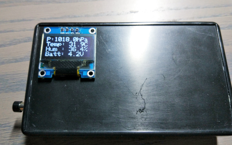
Here the PCB:
-
RE: Gas Meter Reading Using a Magnetometer
@dynamite thanks for your answer! do you use a adafruit FRAM in your node?
-
RE: Gas Meter Reading Using a Magnetometer
Hello,
I have a BK-G4L gas meter and I want to build a Mysensor node and measure the gas flow: what is the best solution, a reed switch or a magnetometer?
and for a magnetometer based sensor, do I need HMC5883 or HMC5983?
thanks -
RE: ESP8266 as WiFi gateway that posts to Thingspeak
@Lendog Hello, is the sketch compatible with Mysensosr 2.0 ?
thanks -
RE: Windows GUI/Controller for MySensors
@pdey said:
@Mark-Swift : If you're happy to modify the MySensors library in an unsupported way, I've added a logMessage function to transmit text/debug messages from remote nodes:
https://github.com/peterdey/MySensors-Arduino/commit/f5f339b71620ec3cd896304a2ca6aba40ad40218Found it useful, particularly in conjunction with MYSController OTA firmware updates.
is it possible to use with mysensor 2.0 API ?
-
RE: PCBs for battery based sensor
@ileneken3
my PCB use a cheap and easily available TP4056 charger, for LiFeP04 batteries you can use charger like this: https://www.tindie.com/products/xorbit/lifepo4weredusb/but I have good news, I found an interesting article http://nerdralph.blogspot.it/2016/01/a-36v-lifepo4-charger-for-under-50c.html maybe I can integrate a LiFePO4 charger on my PCB
-
RE: Easy/Newbie PCB for MySensors
hi @sundberg84, if you have some free time you can see my post about a "new" PCB
https://forum.mysensors.org/topic/5314/pcbs-for-battery-based-sensor -
RE: Air Quality Sensor
@epierre said:
@jumping you will need to scale down the script obviously, in term of power it will be too short to have more than one.
thanks for your answer! please, can you explain how the following code in your sketch is related to datasheet?
- float CO_secCurve[2] = {726.7809737, -4.040111669}; //MQ135
I understand the sketch in the "Gas Detection - Example", but not the previous.
sorry for my poor english -
RE: PCBs for battery based sensor
- PCB with SMD resistors and capacitors with LIPO module, arduino module and radio module
-
PCBs for battery based sensor
Hello,
I'm working on two projects, both of them with RFM and NRF option: what do you think? Are the PCBs correct?- First PCB
- First PCB
-
RE: Easy/Newbie PCB for MySensors
@ileneken3 in my experienxe the 3.3v booster gives a lot of problem with radio
-
RE: Air Quality Sensor
Hello,
I bought the classic MQ sensors (MQ2, MQ4 and MQ135) and I'm building a multisensor node with arduino nano v3:
@epierre can I use sketch https://github.com/empierre/arduino/blob/master/AirQuality-Multiple_Gas_Sensor1_4.ino, is it suitable?
thanks -
RE: Multisensor node using Ceech board
Hello,
I use a My Sensors 2.0 version of "Multisensor node using @ceech board" but I have this error:TSP:MSG:SEND 5-5-0-0 s=255,c=3,t=11,pt=0,l=12,sg=0,ft=1,st=ok:JMP-LightLux TSP:MSG:SEND 5-5-0-0 s=255,c=3,t=12,pt=0,l=3,sg=0,ft=0,st=ok:1.0 TSP:MSG:SEND 5-5-0-0 s=10,c=0,t=13,pt=0,l=0,sg=0,ft=0,st=ok: TSP:MSG:SEND 5-5-0-0 s=11,c=0,t=13,pt=0,l=0,sg=0,ft=0,st=ok: TSP:MSG:SEND 5-5-0-0 s=1,c=0,t=16,pt=0,l=0,sg=0,ft=0,st=ok: Request registration... TSP:MSG:SEND 5-5-0-0 s=255,c=3,t=26,pt=1,l=1,sg=0,ft=0,st=ok:2 TSP:MSG:READ 0-0-5 s=255,c=3,t=27,pt=1,l=1,sg=0:1 Node registration=1 Init complete, id=5, parent=0, distance=1, registration=1 BH1750 lux: 387TSP:MSG:SEND 5-5-0-0 s=1,c=1,t=37,pt=3,l=2,sg=0,ft=0,st=ok:387 Batt: 3.74V ; 414.08mA Solar: 0.00V ; 0.00 mA; charge: Yes BattPct: 61% TSP:MSG:SEND 5-5-0-0 s=10,c=1,t=38,pt=7,l=5,sg=0,ft=0,st=ok:3.738 TSP:MSG:SEND 5-5-0-0 s=10,c=1,t=39,pt=7,l=5,sg=0,ft=0,st=ok:0.414 TSP:MSG:SEND 5-5-0-0 s=11,c=1,t=38,pt=7,l=5,sg=0,ft=0,st=ok:0.000 TSP:MSG:SEND 5-5-0-0 s=11,c=1,t=39,pt=7,l=5,sg=0,ft=0,st=ok:0.000 !TSP:MSG:SEND 5-5-0-0 s=255,c=3,t=0,pt=1,l=1,sg=0,ft=0,st=fail:61
after that the node doesn't send data to gateway.
Do you have some ideas to solve the problem?
thanks -
RE: Strange behaviour with DC 3.3v step-up booster
Hello @AWI thanks for you reply, I will read the document!
With other sensors I use LiOn Nokia/Samsung battery, and it's ok!
But I want to solve this little issue -
RE: Strange behaviour with DC 3.3v step-up booster
Hello,
yesterday I added a 0,1uF capacitor between 3,3V and GND pins and I tried 8 different step-up booster without success!In the next days I will try different configurations to understand what is happening!
-
RE: Strange behaviour with DC 3.3v step-up booster
Thanks for your answers!
I will try with a 0.1uF ceramic capacitor.@sundberg84 yes, I only have added the jumper on "BAT"
-
Strange behaviour with DC 3.3v step-up booster
Hello,
my "mysensors" nodes are based upon a modified version of Easy/Newbie PCB (https://www.mysensors.org/hardware/newbie-pcb).
The nodes work fine with battery supply but without the step-up booster,
when I use a 3,3v DC step-up booster, the transmission with the gateway fails:Starting sensor (RNNNA-, 2.0.0) TSM:INIT TSM:RADIO:OK TSM:FPAR TSP:MSG:SEND 255-255-255-255 s=255,c=3,t=7,pt=0,l=0,sg=0,ft=0,st=bc: TSM:FPAR TSP:MSG:SEND 255-255-255-255 s=255,c=3,t=7,pt=0,l=0,sg=0,ft=0,st=bc: TSM:FPAR TSP:MSG:SEND 255-255-255-255 s=255,c=3,t=7,pt=0,l=0,sg=0,ft=0,st=bc: TSM:FPAR TSP:MSG:SEND 255-255-255-255 s=255,c=3,t=7,pt=0,l=0,sg=0,ft=0,st=bc: !TSM:FPAR:FAIL !TSM:FAILURE
Other info:
- 47uF capacitor beetween VCC and GND
- mysensors version is 2.0
Do you have any idea to solve the problem?
Thank you for your help!