A little Halloween fun. I've added LED strip lights to an old Halloween plastic ghost and jack-o-lantern and automated switching them off/on using a MySensors node.




A little Halloween fun. I've added LED strip lights to an old Halloween plastic ghost and jack-o-lantern and automated switching them off/on using a MySensors node.


@ejlane Yes, my speakers are best described as MQTT Text to Speech output devices. Basically, I wrote a small application which runs on a phone using MIT App Inventor. It subscribes to the Speak topic on my local MQTT broker. Whenever someone publishes to the Speak topic, it converts the text to speech. I have quite a few automations in Home Assistant which publish to Speak. I have 3 old phones set up as speakers around my house.
Regarding AI smart speakers, there is a lot of new stuff out there, with the release of tinyML.
From what I've read, the easiest type of speech recognition is "Keyword spotting" - see Edge Impulse
The next level is "Speech to Intent" - see Wio Terminal TinyML course
And the highest level is Large-vocabulary continuous speech recognition.
![20210612_201851[1].jpg](/assets/uploads/files/1623550358863-20210612_201851-1-resized.jpg)
Hi All,
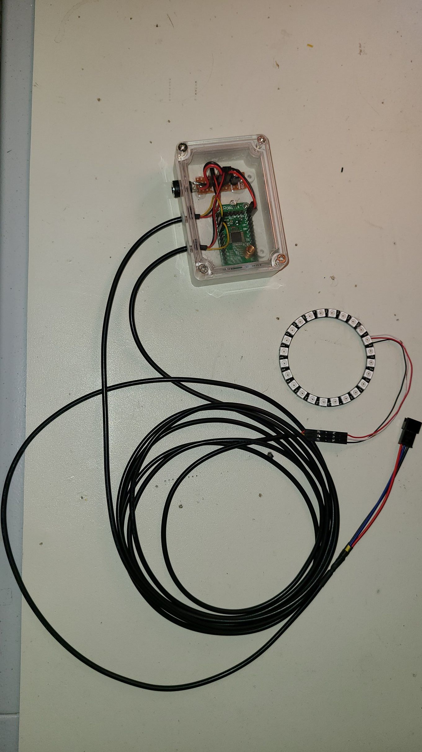
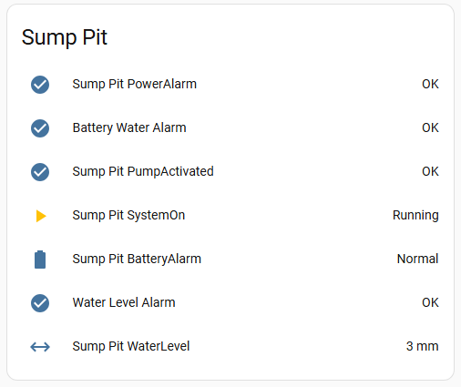
I recently replaced my sump pit pump and installed a battery backup pump at the same time. Naturally, when I saw all the alarms available on the backup system, I wanted to integrate them into my home automation system. I also wanted to add a water level sensor to get a better idea of how often the pump ran and also create a water level alarm.
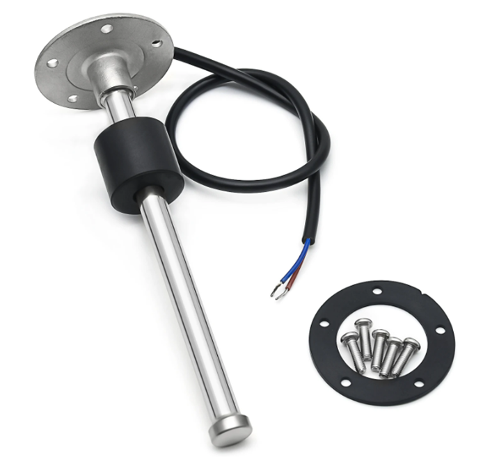
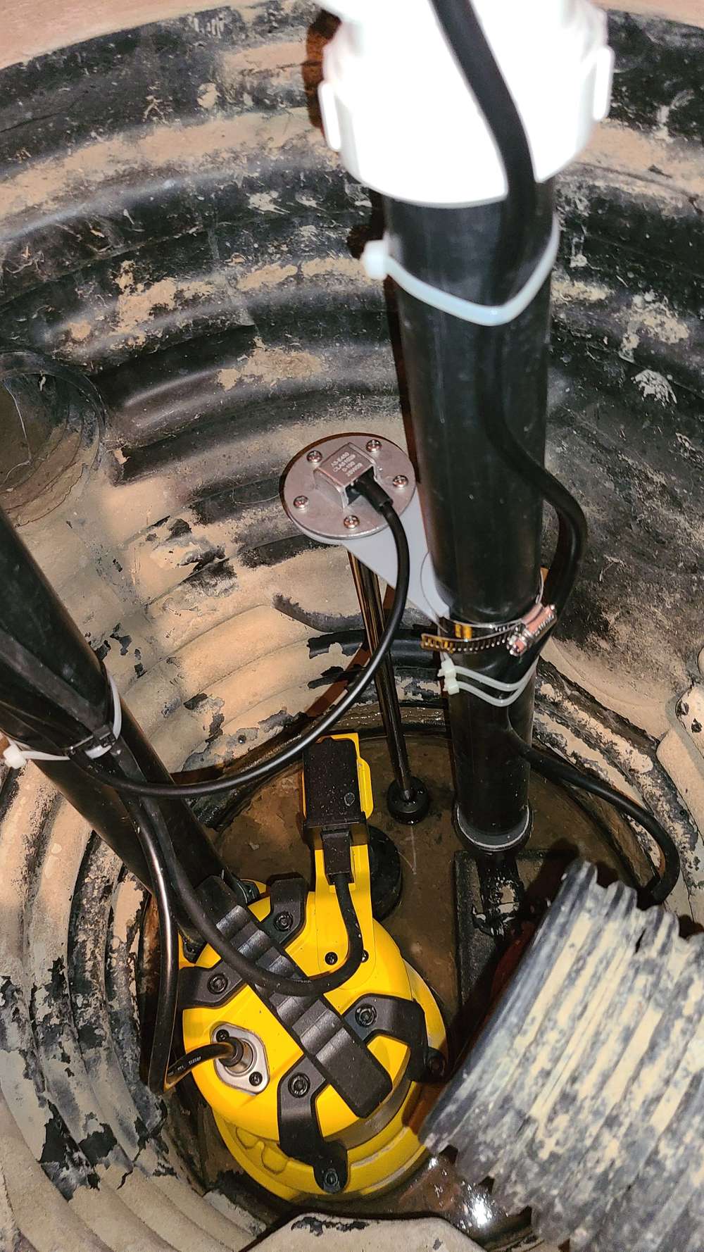
Water level sensor installed.
I looked at the backup controller and realised it would be difficult to pull signals from it since it isn't easy to disassemble. So, I opted to used photo transistors to read the state of the alarm LEDs.
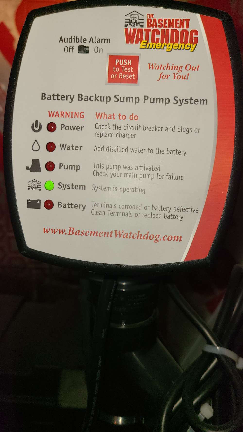
The photo transistors are held in place with velcro strips for easy removal.
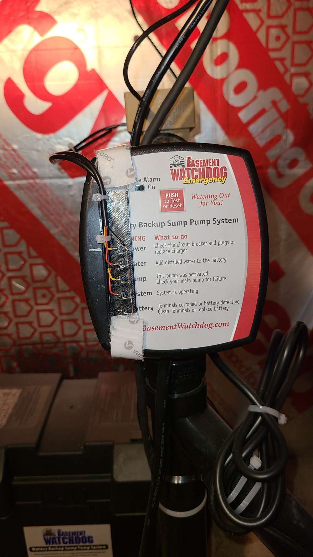
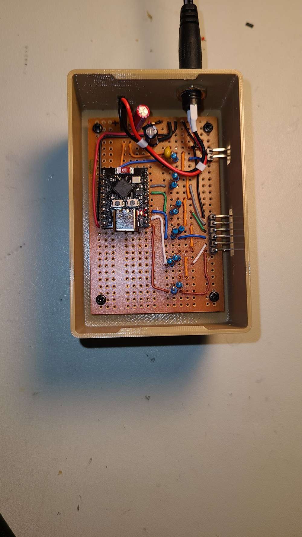
My monitoring node consists of an ESP32C3 Super Mini ucontroller configured with 5 digital input channels and 1 analog channel to read the alarm LEDs and water level. I'm using MQTT, for this project, to send the data to Home Assistant.
Integrated into Home Assistant
Overall, after a few adjustments, the systems works really well and provides some peace of mind.
Hi electrik,
Yes, my nodes send the sketch name within the presentation function.
As for the gateway, I have not set up a sketch name, the example I found did not implement this, so I didn't think it
was necessary?
I manually named the gateway node in the configuration.yaml file, and the "missing sketch name" message no longer appears in the log. I guess, I'll add an entry for node 0 (controller) as well .
I'm still getting the "USB0 not ready after 15.0 secs" at startup, but all seems to work regardless.
I connected the gateway to my pc using mycontroller, it all works fine. Logs look normal.
Here is the code for one of my nodes, a temperature node with Arduino mini & RFM69 radio, running on battery.
// Enable debug prints to serial monitor
#define MY_DEBUG
#define MY_BAUD_RATE 38400

// Enable and select radio type attached
//#define MY_RADIO_RF24
#define MY_RADIO_RFM69
#define MY_IS_RFM69HW
#define MY_RFM69_FREQUENCY  RFM69_915MHZ

#include <MySensors.h>
#include <DallasTemperature.h>
#include <OneWire.h>

#define COMPARE_TEMP 0 // Send temperature only if changed? 1 = Yes 0 = No

#define ONE_WIRE_BUS 8 // Pin where dallas sensor is connected

#define CHILD_ID_TEMP 0
#define CHILD_ID_BATT 1

// function protos
void ReadBat(double& b, uint8_t& bPct);

unsigned long SLEEP_TIME = 300000;    // Sleep time between reads (5min) (in milliseconds)
const int BAT_V = A0;                 // battery voltage, AnaIn 0

OneWire oneWire(ONE_WIRE_BUS);        // Setup a oneWire instance to communicate with any OneWire devices (not just Maxim/Dallas temperature ICs)
DallasTemperature sensors(&oneWire);  // Pass the oneWire reference to Dallas Temperature.

float lastTemperature;
double bat, lastBat=0.0;
uint8_t batPct;
int numSensors=0;
bool receivedConfig = false;
bool metric = true;
bool initialValuesSent = false;
bool initialValTempSent = false;
bool initialValBatSent = false;

// Initialize message objects
MyMessage msg(CHILD_ID_TEMP, V_TEMP);
MyMessage msgBatt(CHILD_ID_BATT, V_VOLTAGE);

void before()
{
  // Startup up the OneWire library
  sensors.begin();
}

void setup()
{
  sensors.setWaitForConversion(false);
  // requestTemperatures() will not block current thread
  Serial.print("Found ");
  Serial.print(sensors.getDeviceCount(), DEC);
  Serial.println(" temperature devices.");
  sensors.requestTemperatures();
}

void presentation() {
  Serial.println("Sending presentation");
  // Send the sketch version information to the gateway and Controller
  sendSketchInfo("Temperature Sensor", "1.2");
  // Present all sensors to controller
  present(CHILD_ID_TEMP, S_TEMP, "Bed room Temperature");
  present(CHILD_ID_BATT, S_MULTIMETER, "Bed room node Voltage");
}

void loop()
{
  int16_t conversionTime = 0;
  float temperature = 0;

  if (!initialValuesSent) {
    Serial.println("Sending initial value");
    // Read in the battery voltage
    ReadBat(bat, batPct);
    // get temperature conversion time
    conversionTime = sensors.millisToWaitForConversion(sensors.getResolution());
    wait(conversionTime);
    // Fetch temperature
    temperature = sensors.getTempCByIndex(0);
    // send the temperature reading
    // set(float value, uint8_t decimals)
    send(msg.set(temperature, 2));
    Serial.println("Requesting initial Temp value from controller");
    request(CHILD_ID_TEMP, V_TEMP);
    wait(2000, C_SET, V_TEMP);
    // send bat voltage
    send(msgBatt.set(bat, 2));
    Serial.println("Requesting initial Batt value from controller");
    request(CHILD_ID_BATT, V_VOLTAGE);
    wait(2000, C_SET, V_VOLTAGE);
  }
//  {
  else {
    // Fetch temperatures from Dallas sensors (non-blocking)
    sensors.requestTemperatures();
    // Read in the battery voltage
    ReadBat(bat, batPct);

    // query conversion time and sleep until conversion completed
    conversionTime = sensors.millisToWaitForConversion(sensors.getResolution());

    // sleep() call can be replaced by wait() call if node need to process incoming messages (or if node is repeater)
    sleep(conversionTime);

    // Read temperature and send to controller
    // Fetch temperature
    temperature = sensors.getTempCByIndex(0);
    Serial.println("temperature: ");
    Serial.println(temperature);

    // Only send data if temperature has changed and no error
    #if COMPARE_TEMP == 1
    if (lastTemperature != temperature && temperature != -127.00 && temperature != 85.00) {
    #else
    if (temperature != -127.00 && temperature != 85.00) {
    #endif
      // Send in the new temperature
      // set(float value, uint8_t decimals)
      send(msg.set(temperature, 2));
      // Save new temperatures for next compare
      lastTemperature=temperature;
    }
    // Send in the new battery level
    sendBatteryLevel(batPct);
    send(msgBatt.set(bat, 2));
    // Save the battery level for next compare
    lastBat = bat;
    Serial.println("Sleep...");
    sleep(SLEEP_TIME);
  }
}

void receive(const MyMessage &message) {
  if (message.isAck()) {
     Serial.println("This is an ack from gateway");
  }

  if (message.type == V_TEMP) {
    if (!initialValTempSent) {
      Serial.println("Received initial temp value from controller");
      initialValTempSent = true;
    }
  }
  else if (message.type == V_VOLTAGE) {
    if (!initialValBatSent) {
      Serial.println("Received initial bat value from controller");
      initialValBatSent = true;
    }
  }
  if (initialValTempSent && initialValBatSent)
    initialValuesSent = true;
}

// b - battery voltage
// bPct - battery percent
void ReadBat(double& b, uint8_t& bPct)
{
  long sumBat=0;
  int i;

  // take average over 64 readings
  for (i = 0; i < 64; ++i) {
    // read & sum battery voltage
    sumBat += analogRead(BAT_V);
  }
  sumBat = sumBat >> 6;      // shift 6 -> divide by 64
  b = sumBat*3.3/1023.0;
  bPct = (uint8_t)(sumBat*100.0/1023.0);
}
Here is the serial gateway sketch:
#include <SoftwareSerial.h>
SoftwareSerial softSerial(8, 9); // RX, TX

// Enable debug prints to serial monitor
#define MY_DEBUG
#define MY_DEBUGDEVICE softSerial
// You also need to create softSerial in setup()

// Enable and select radio type attached
//#define MY_RADIO_RF24
//#define MY_RADIO_NRF5_ESB
//#define MY_RADIO_RFM95
#define MY_RADIO_RFM69
#define MY_IS_RFM69HW
#define MY_RFM69_FREQUENCY  RFM69_915MHZ


// Set LOW transmit power level as default, if you have an amplified NRF-module and
// power your radio separately with a good regulator you can turn up PA level.
//#define MY_RF24_PA_LEVEL RF24_PA_LOW

// Enable serial gateway
#define MY_GATEWAY_SERIAL

// Define a lower baud rate for Arduinos running on 8 MHz (Arduino Pro Mini 3.3V & SenseBender)
#if F_CPU == 8000000L
#define MY_BAUD_RATE 38400
#endif

// Enable inclusion mode
#define MY_INCLUSION_MODE_FEATURE
// Enable Inclusion mode button on gateway
//#define MY_INCLUSION_BUTTON_FEATURE

// Inverses behavior of inclusion button (if using external pullup)
//#define MY_INCLUSION_BUTTON_EXTERNAL_PULLUP

// Set inclusion mode duration (in seconds)
#define MY_INCLUSION_MODE_DURATION 60
// Digital pin used for inclusion mode button
//#define MY_INCLUSION_MODE_BUTTON_PIN  3

// Set blinking period
#define MY_DEFAULT_LED_BLINK_PERIOD 300

// Inverses the behavior of leds
//#define MY_WITH_LEDS_BLINKING_INVERSE

// Flash leds on rx/tx/err
// Uncomment to override default HW configurations
//#define MY_DEFAULT_ERR_LED_PIN 4  // Error led pin
//#define MY_DEFAULT_RX_LED_PIN  6  // Receive led pin
//#define MY_DEFAULT_TX_LED_PIN  5  // the PCB, on board LED

#include <MySensors.h>

void setup()
{
  softSerial.begin(38400);
}

void presentation()
{
	// Present locally attached sensors
}

void loop()
{
	// Send locally attached sensor data here
}
Thanks.
The motion sensor is used to turn on the lights in the garage via a Sonoff mini.
Also, I've had the garage door randomly open by itself (power glitches?) a few times over the years. So I'm adding an automation to close the door if no motion is present and it is after midnight.
Hi everyone,
I'd like to share my latest project.
I've built up a node which monitors our washing machine for leaks and monitors our dryer for operation.
The node uses an arduino pro mini with an RFM69 radio. It runs continuously on a 5V wall wart supply regulated down to 3.3V.
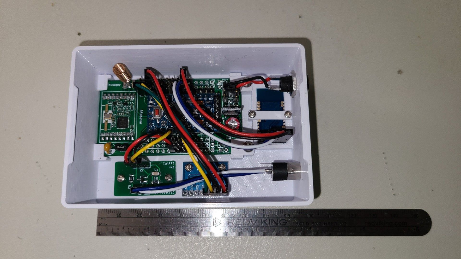
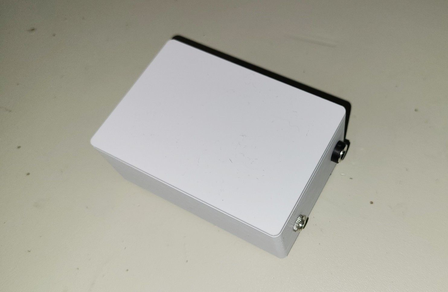
The leak sensor is a classic probe type with 2 parallel conductors and a signal conditioner board (transistor based) which generates an analog voltage to represent the leak signal. When the signal exceeds the programmed threshold the leak is reported (using a binary sensor).

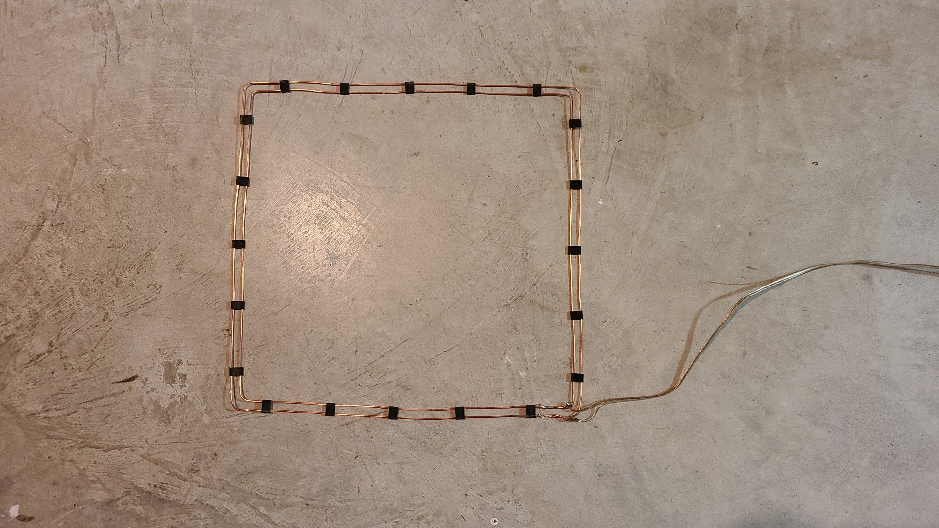
I used 14 gage solid copper wire to make the probe.
Dryer operation is sensed using an MPU-6050 accelerometer. I use the absolute value of the vibration signal and pass it through a moving average filter to get a steady signal.
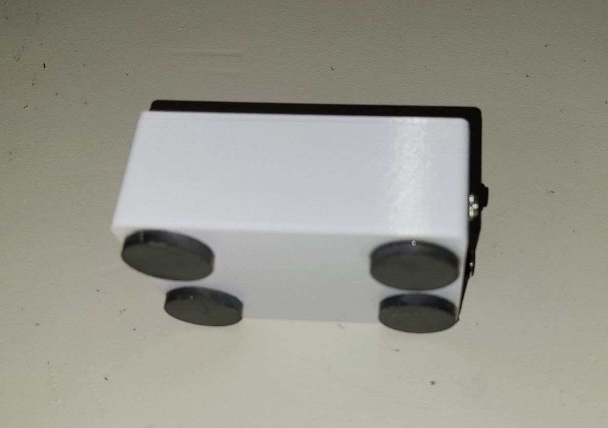
The node is mounted to the dryer using magnets glued to the enclosure.
I also threw in a JDY-31 bluetooth module for serial monitoring/debug. So cheap and easy, why not?!
The vibration threshold can be set in Home Assistant, to allow for easy fine tuning.
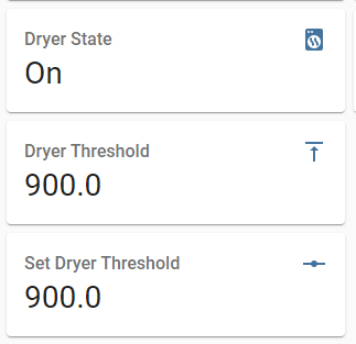
I also added running statistics, updated every minute, of min (var1), max (var2) and average (var3) vibration levels to make it easier to set the threshold.
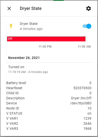
And to keep the wife happy :stuck_out_tongue_winking_eye: , I have our home made smart speakers announce when the dryer is done.
@ejlane Oh, now I get your question. Text to Speech is built into the Android OS on the phone. There is a synthesis engine which runs on the phone and generates the speech. Although it likely has networked features, for example, loading different voices.
Project Alice looks quite interesting. I'll definitely be digging deeper. I see it runs on Raspberry Pi's, maybe it will run on my Ubuntu server too.
Finished my Garage Door Node.
It has open/close magnetic reed switch sensors, a DS18B20 temperature sensor, a PIR motion sensor and a bjt to trigger the door to open/close/stop.
@mfalkvidd Thanks. Yes those are spacers that snap on to the wires. I 3d printed them as well as the enclosure.
Documenting what I've found in the library code for the community.
When using #define MY_IS_RFM69HW:
The driver enables PA1 and PA2 and disables PA0 power amps. It automatically selects the right combination of PA1 and PA2 to achieve the target power level.
Power range is -2 to +20 dBm
When NOT using #define MY_IS_RFM69HW:
Then only PA0 is enabled.
PA0 is identical between the RFM69W and RFM69HW.
Power range is -18 to +13 dBm
Basically, your RFM69HW operates as an RFM69W.
Also, when using the new RFM69 driver, ATC mode is on by default, unless you explicitly turn it off using macro #define MY_RFM69_ATC_MODE_DISABLED
The default ATC target RSSI level is -80 dBm which you can change using #define MY_RFM69_ATC_TARGET_RSSI_DBM
Cheers
HI @Henil179
I made one myself a couple of years ago, and yes, it was a fair bit of trial and error to get it working.
Of course, the gain values will be dependent on a number of factors, for example, the torque constant of your motor, the gear ratio, the mass of the robot, where your centre of gravity is located, your loop rate, and where you've located your mpu-6050.
I located my mpu-6050 over the axis at 12 o'clock near the vertical centre of my bot.
What are you control variables?
I used pitch (angle of rotation around motor axis) calculated from gx, gz and tan function.
I also used pitch rate from the gyro.
Are you using the onboard DSP of the mpu-6050 to do the calculations?
I had no luck with this, the mpu-6050 kept freezing up, bad clone I guess.
You also have to verify the direction of rotation of your motor versus your control variables.
If you have the wrong direction, it will just run away.
My gains are Kp:41, Ki:160, Kd:0.4
I started with only Kp and kept increasing the value until the system became unstable, then I backed off to a stable point.
Next, I began increasing Ki. This will bring you to steady state stability. It should balance itself when Kp & Ki.
You will likely have to reduce Kp somewhat as you move to higher Ki values, if your system becomes unstable.
Finally, I added Kd, to help it react more quickly to changes in angle.
How do you change your gains?
I have a bluetooth module on mine, to allow me to send serial commands to the robot, to set the gains and other things.
My robot's biggest problem is gear backlash. This generates acceleration noise as it vibrates backward/forward, balancing itself. This vibration can feedback on itself and cause instability (when you increase Kp too high). It looks like the robot has Parkinsons when this happens! :grinning:
I'd like to update my design to use a belt/gear drive or continuous rotation servo, but I haven't had a chance to get back to it.
I hope this helps.
@ejlane So far, I have a leak sensor under my clothes washer and hot water heater. I got the idea after my dish washer began leaking and damaged my kitchen cabinets. Dish washer is next...
I should clarify regarding the smart speaker. They really are MQTT text to speech speakers built from old cell phones I had laying around the house. I wrote an app in MIT app inventor. It could be expanded to play mp3 files of course and displaying images too.
I would like to create a smart speaker using Jetson Nano, but I haven't gotten around to it yet. Smart speakers might be an idea for a new thread. I haven't looked into it very deeply and could use some ideas too. :slightly_smiling_face:
@scalz
This is my first attempt at using the lower power PA0. I am getting an RSSI of -75 with the radios about 5m apart and the radio using 10 dBm to achieve this. Quite disappointing. I was expecting the transmit power to be much lower, since in High Power mode I was getting an RSSI of -45 with transmit power of -2 dBm.
I thought that perhaps the radio was reporting the wrong transmit power, or that the library was not interpreting it correctly. I expected results similar to the data sheet.
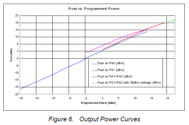
But you say this is a common problem!
I was planning on standardising on the high power radio for all my nodes, but now I see I will have to switch to the RFM69W for many of them.
Thanks very much for taking the time to bring me up to speed, its greatly appreciated.
@CrankyCoder The code can be found on Github: Washer-Dryer-Monitor
Hi @Leonel-Epps.
My pleasure, I've gotten a lot of good ideas from the Forum, its always good to give back.
P.S.
My washing machine leak sensor alerted me to a leak about 3 weeks. I checked, and sure enough, there was a small puddle of water under the machine. The door seal was wearing and had a few tears in the bellows.
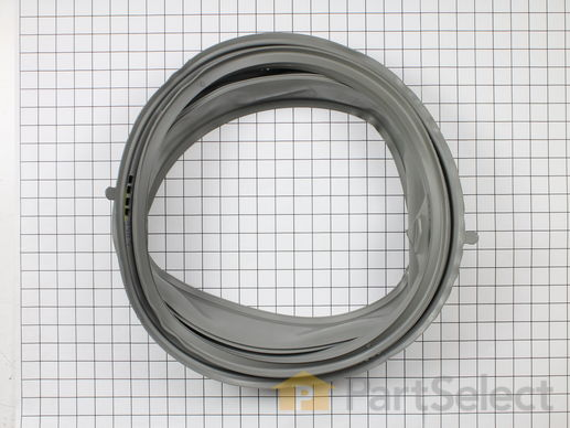
I replaced the door seal (thank you youtube videos) and all is good. The washing machine is on the upper floor in my home and could have done serious damage to the lower level if it hadn't been detected quickly.
Regards,
KevinT
@kiesel Looks like you are well on your way.
If you post a schematic, you'll likely get more feedback.
If you are using one of those Chinese step up converters to 3.3V, I found I had to add a 1 uF cap on Vin to get good performance at no load.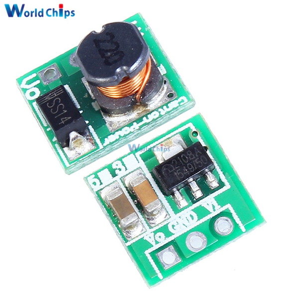
Most designs I've seen also have a 0.1 uF decoupling cap at the power connections to the radio.
I can't tell where you are connecting the door switch, directly to an unused pins on the pro mini?
One limitation to the pro mini is that you only have 2 interrupts and 1 is used for the radio, leaving you 1 for your project, which is probably fine for your application.
If you used a pro micro (32U4) instead, you would have 5 interrupts, leaving 4 for your project. And I don't think I've ever seen an rfm69 board for the pro micro, so it would be a first. Just a thought.
@kiesel Thanks for the schematic.
For the decoupling cap, it should be as close to the 3.3V & Gnd pins of the radio as possible.
Keep us posted, thanks.