Yes, Lol, you have 2 PRs but both have issues. I looked, but I didn't manage to find them on Github/MySensors. I did read that espressif updated their esp8266 core to use standard Arduino yield functions. I guess it's related to that.
K
KevinT
@KevinT
Posts
-
💬 Easy-Peasy Amplified MySensors Serial Gateway -
💬 Easy-Peasy Amplified MySensors Serial GatewayHi @mfalkvidd
I rolled back the esp8266 library to 2.6.2 and it compiles.
Is there an upcoming release to fix this?
Thanks :-) -
💬 Easy-Peasy Amplified MySensors Serial GatewayI know this thread is old but it seems the most relevant. I just tried to compile the standard GatewaySerial.ino sketch using Wemos D1 mini as board type and I get error:
MyMainESP8266.cpp:95:9: error: 'cont_can_yield' was not declared in this scope;I'm using MySensors Library v2.3.2
I'm assuming this used to work. Is it broken or I am doing something wrong?
-
Outdoor Motion Sensor - Surprisingly GoodHi,
The sensor has a lux setting you can adjust to block triggering during daylight, but I just add an "after sunset" condition to my automation script to prevent daylight triggering.
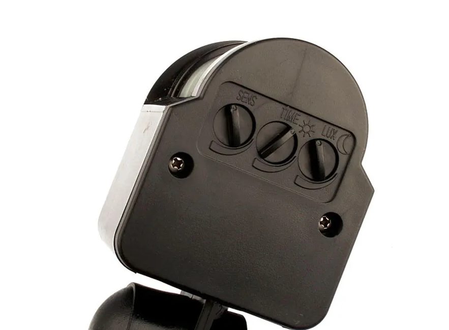
On AliExpress:
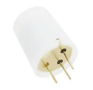
PIR no base
PIR with base -
Outdoor Motion Sensor - Surprisingly GoodHi everyone,
I've wanted to add an motion sensor overlooking my driveway to turn on the outside lights when I return home at night. I wanted something I could integrate into my home automation system, not exterior lights with built in motion sensors.
My search for outdoor motion sensors that could be wired into a MySensors node yielded few results. I have previously used Panasonic pir sensors but they don't work with direct sunlight.
I ended up ordering a sensor on AliExpress.
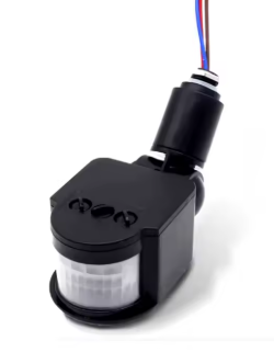
I selected the 12V model, expecting I would need to supply both 12V and 3.3V to my node. Out of curiosity, I tried running the sensor on 5V, and to my surprise, it worked fine. Deciding to push my luck, I tried 3.3V and again, it worked fine!I installed the sensor last fall and it has been working great for 7 months now.
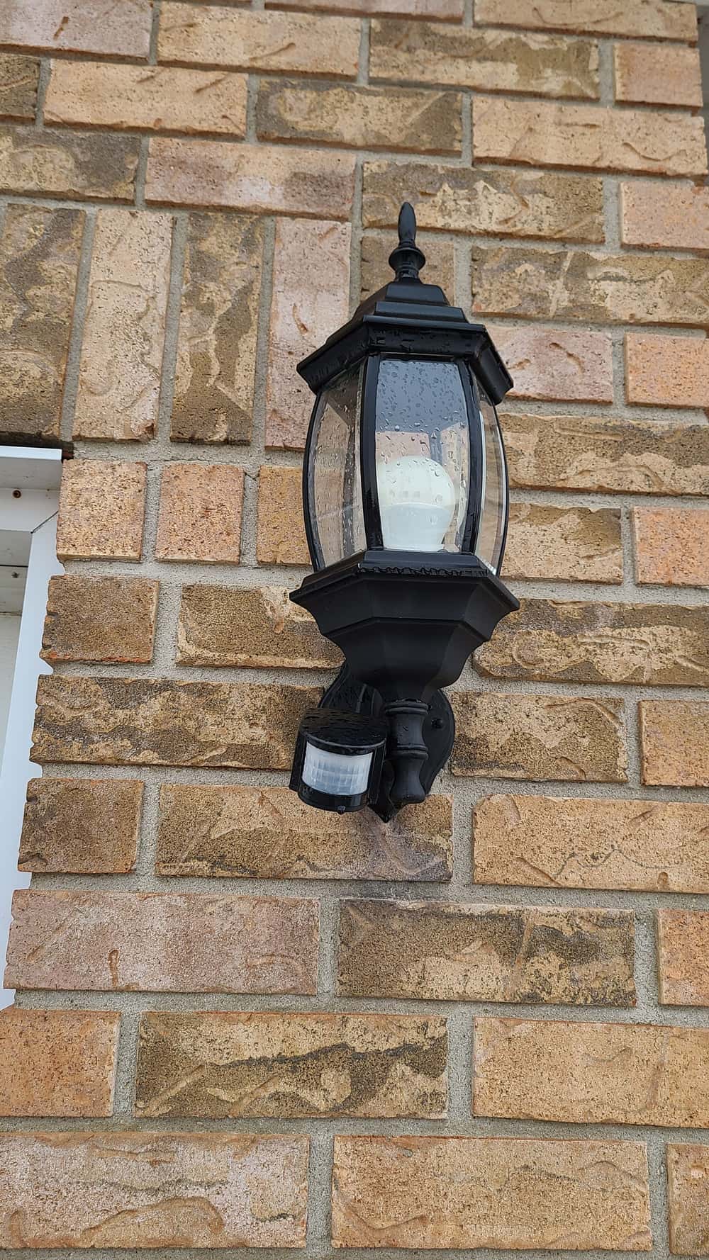
I had to add a load resistor for the sensor to switch properly.
I'm curious, what have other people used for outdoor motion sensors?
-
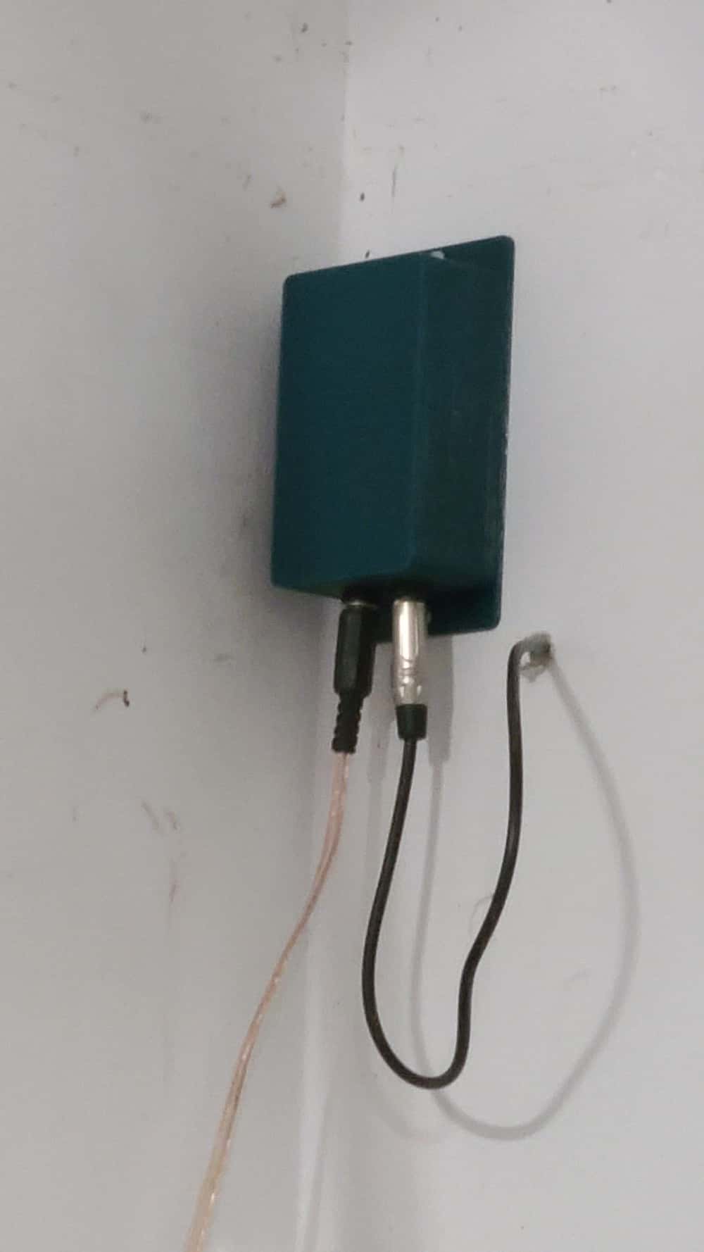
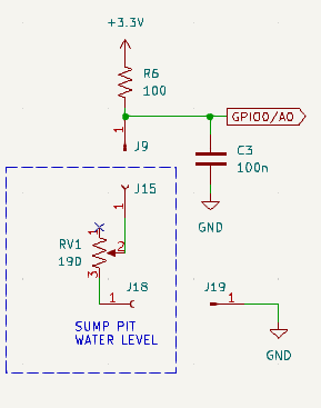
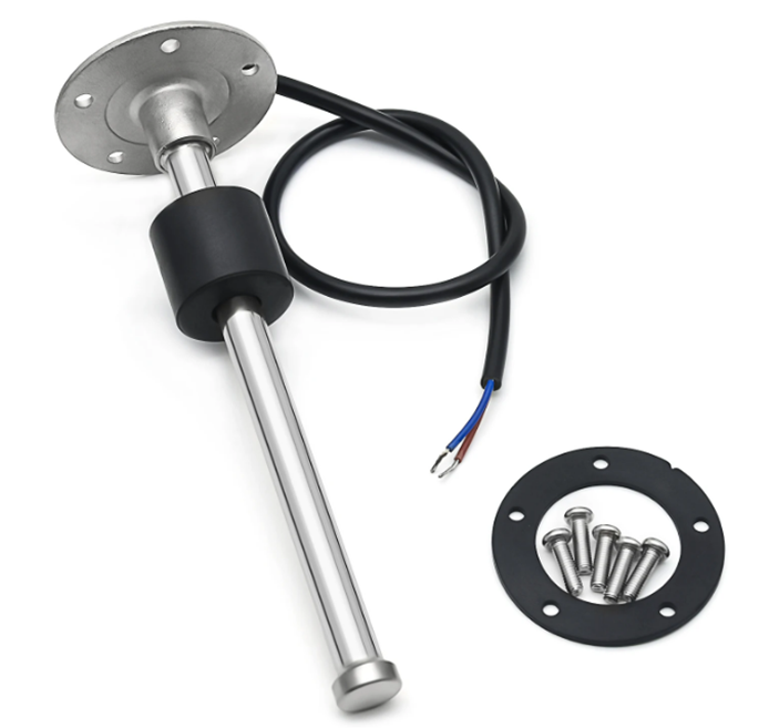
Sump Pit Monitor@TheoL Thanks. As @OldSurferDude says, it's an analog sensor I got off AliExpress Fuel level sensor. I chose a 0-190 ohm sensor, 450 mm long. I wired a 100 ohm resistor in series with the sensor and read the voltage with an analog channel. I do a little extra math to linearise the measurement.
I normally use mysensor nodes, but since this one is always on, I tried using MQTT for a change. -
Sump Pit MonitorHi All,
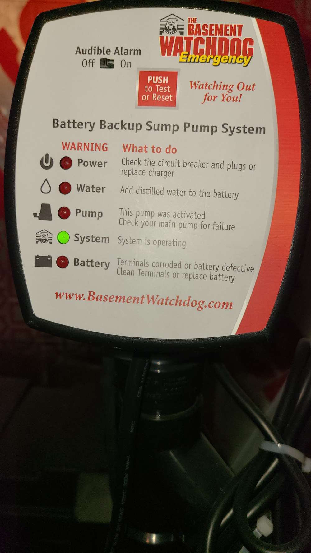
I recently replaced my sump pit pump and installed a battery backup pump at the same time. Naturally, when I saw all the alarms available on the backup system, I wanted to integrate them into my home automation system. I also wanted to add a water level sensor to get a better idea of how often the pump ran and also create a water level alarm.
Water level sensor installed.
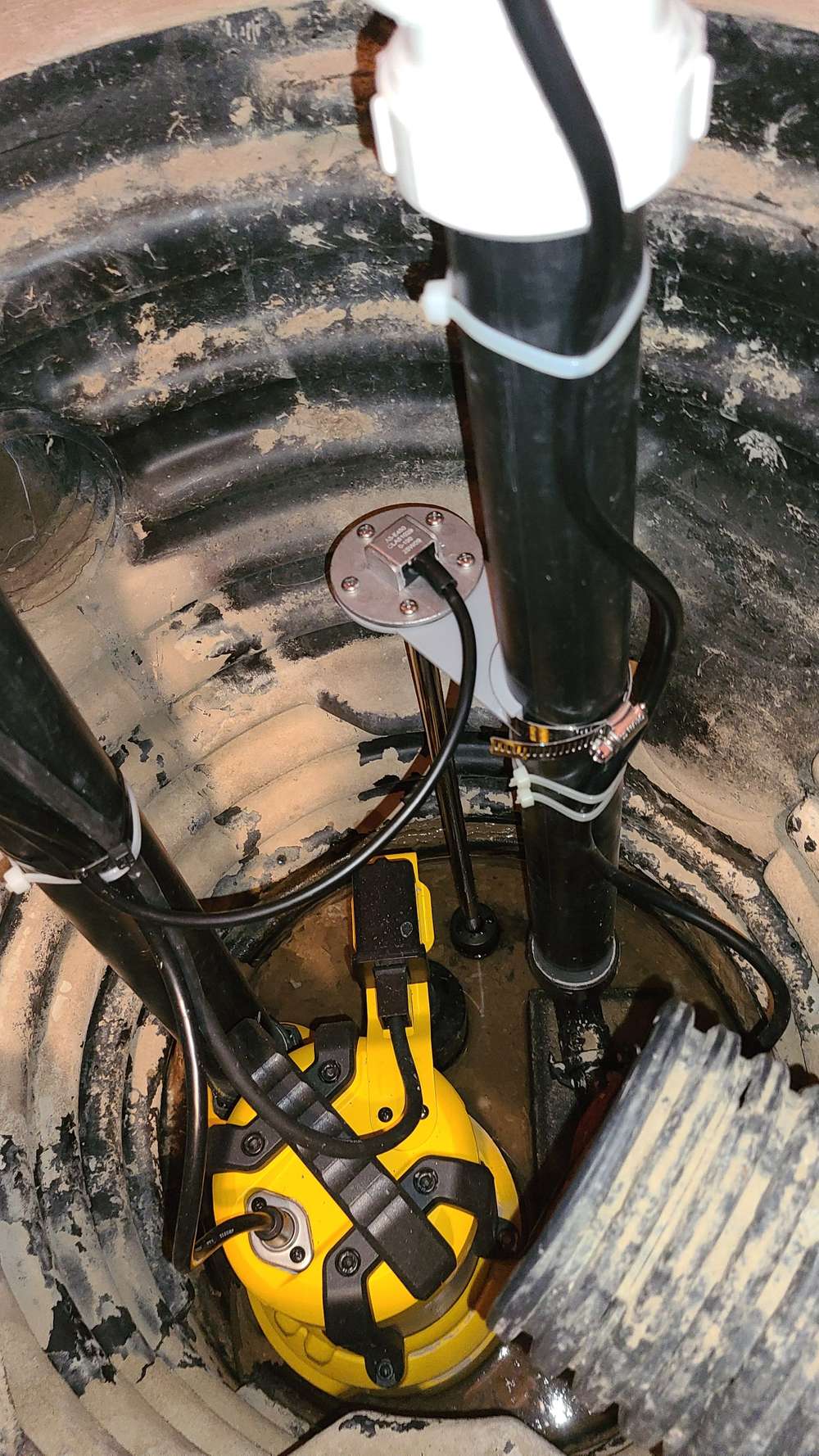
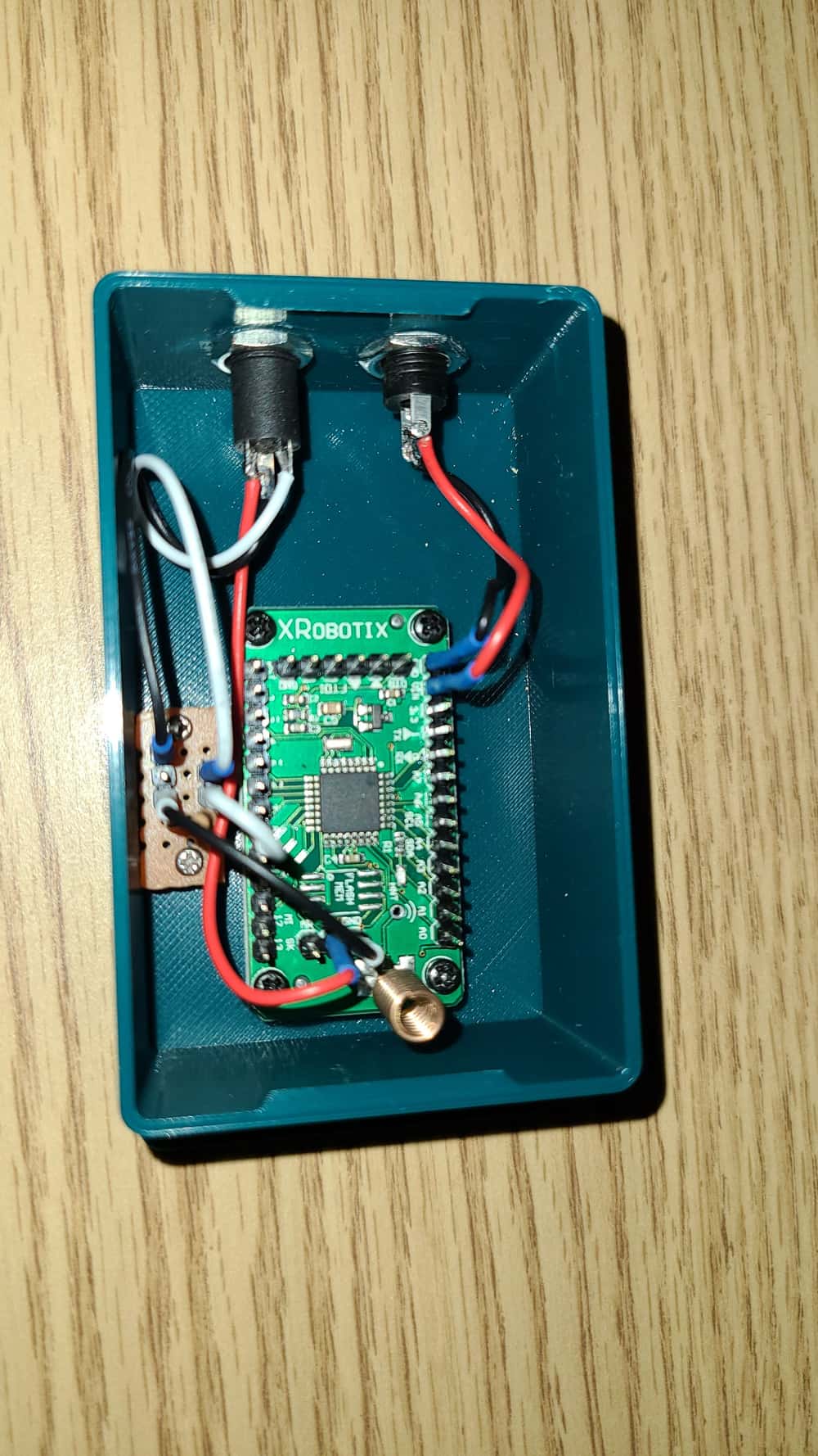
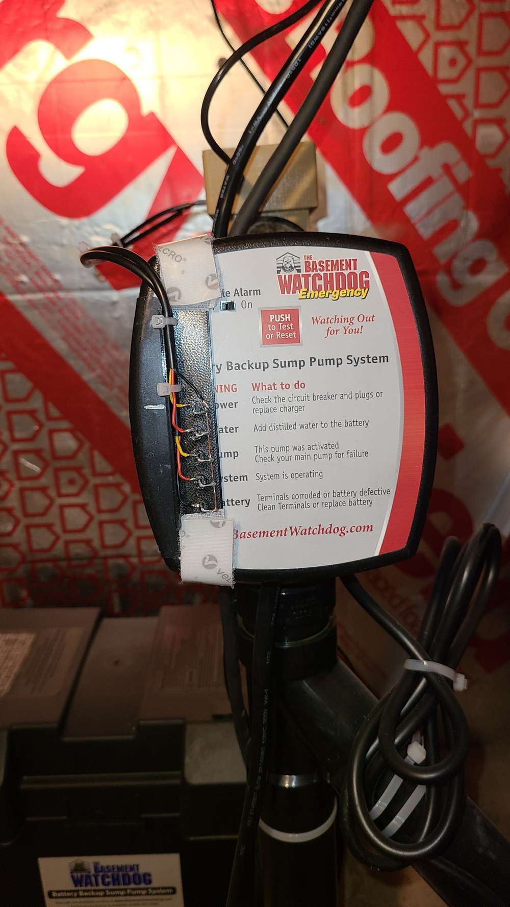
I looked at the backup controller and realised it would be difficult to pull signals from it since it isn't easy to disassemble. So, I opted to used photo transistors to read the state of the alarm LEDs.
The photo transistors are held in place with velcro strips for easy removal.
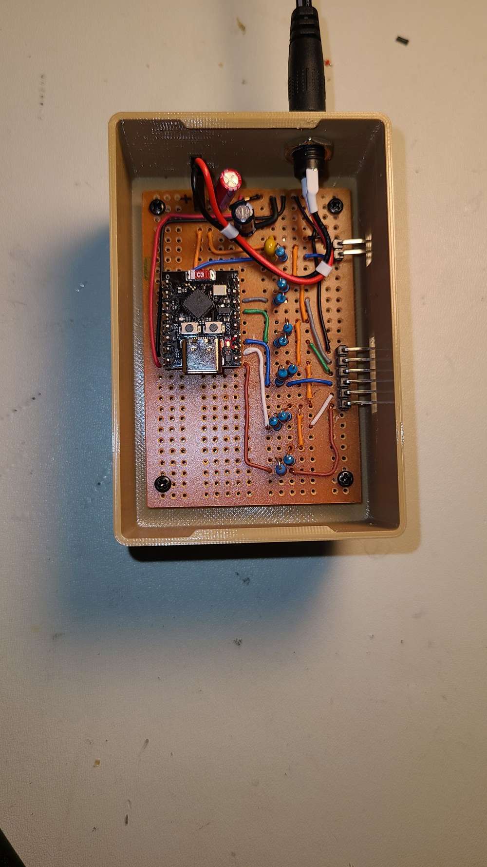
My monitoring node consists of an ESP32C3 Super Mini ucontroller configured with 5 digital input channels and 1 analog channel to read the alarm LEDs and water level. I'm using MQTT, for this project, to send the data to Home Assistant.
Integrated into Home Assistant
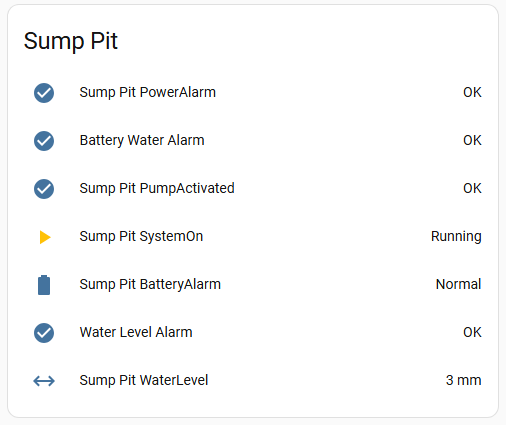
Overall, after a few adjustments, the systems works really well and provides some peace of mind. -
A low cost energy meterHi OldSurferDude,
I just read through your Energy Meter documentation. Nice work. It gives basic theory and calculations. I've been thinking about building an energy meter for a while now. I'll use this as a reference. Thanks. -
HVAC ControllerWow, you're going to be busy. Hope all goes well. Give us an update when you're finished.
-
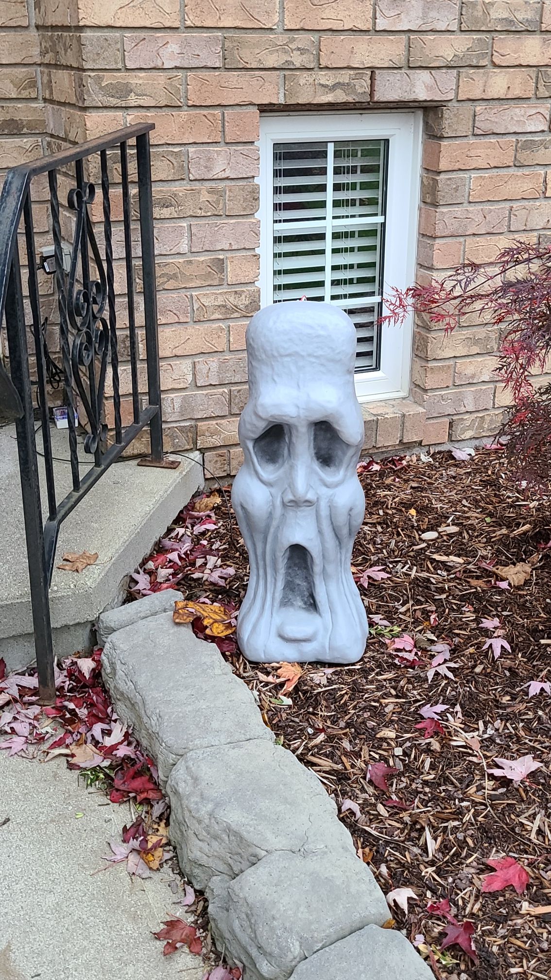
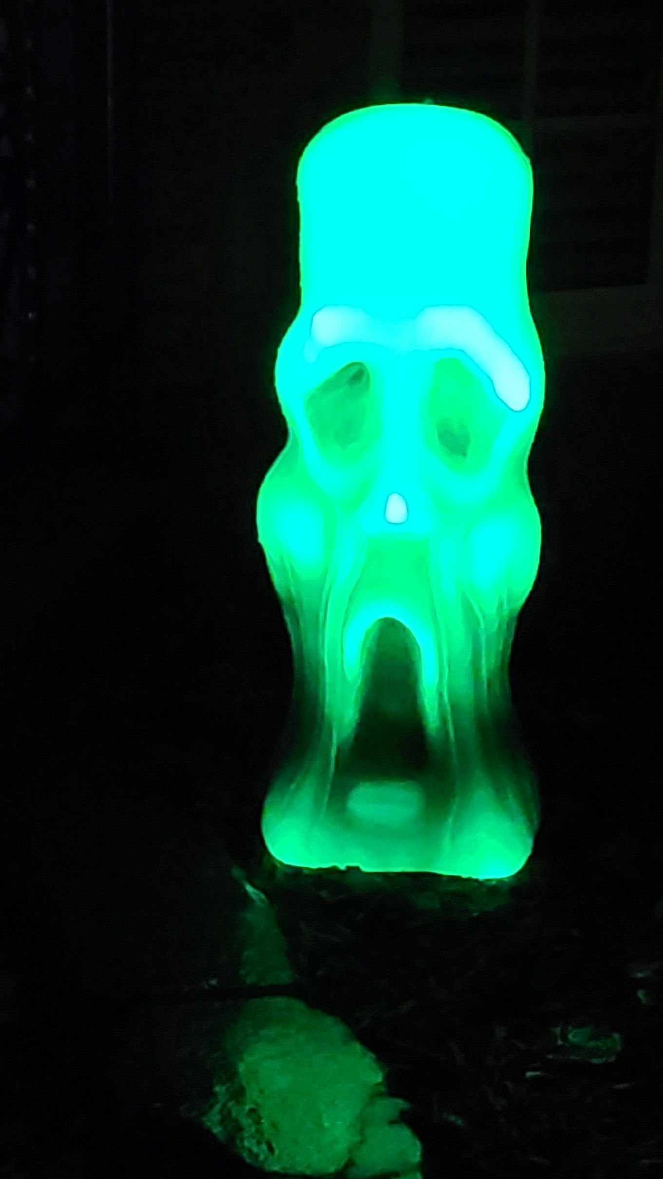
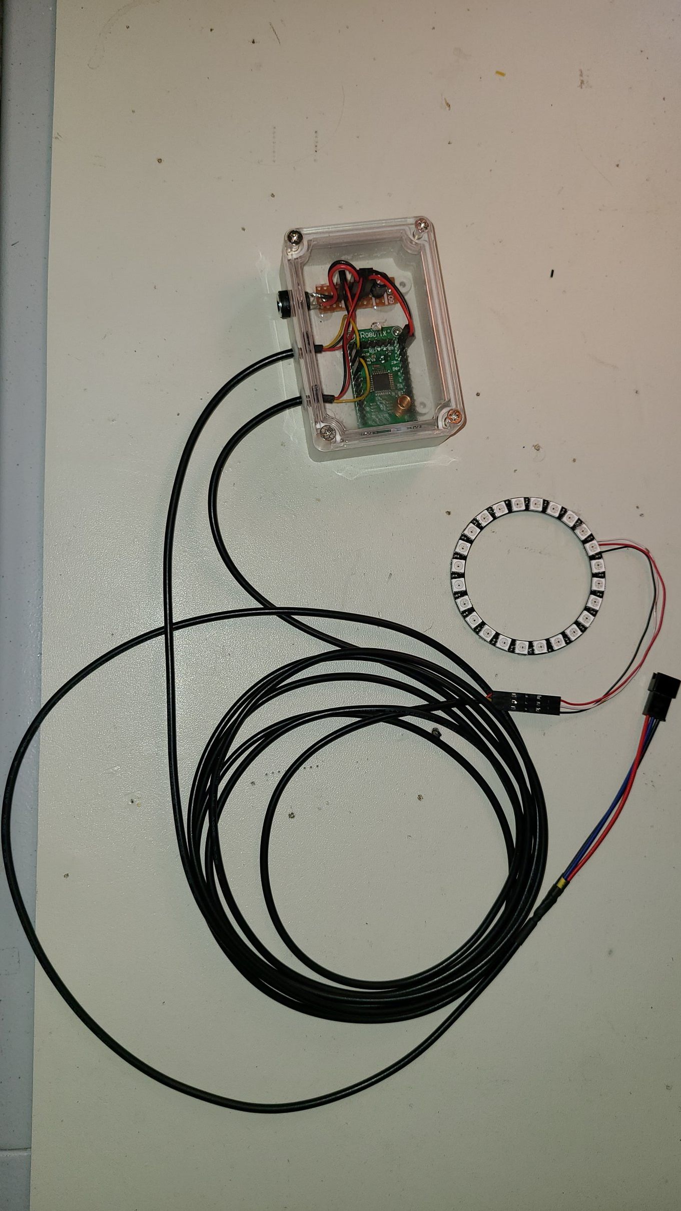
Halloween LightsA little Halloween fun. I've added LED strip lights to an old Halloween plastic ghost and jack-o-lantern and automated switching them off/on using a MySensors node.


-
WIP: My first PCB: Arduino Pro Mini + RFM69 small node (feedback wanted)@kiesel Thanks for the schematic.
For the decoupling cap, it should be as close to the 3.3V & Gnd pins of the radio as possible.
Keep us posted, thanks. -
WIP: My first PCB: Arduino Pro Mini + RFM69 small node (feedback wanted)@kiesel Looks like you are well on your way.
If you post a schematic, you'll likely get more feedback.
If you are using one of those Chinese step up converters to 3.3V, I found I had to add a 1 uF cap on Vin to get good performance at no load.
Most designs I've seen also have a 0.1 uF decoupling cap at the power connections to the radio.
I can't tell where you are connecting the door switch, directly to an unused pins on the pro mini?
One limitation to the pro mini is that you only have 2 interrupts and 1 is used for the radio, leaving you 1 for your project, which is probably fine for your application.
If you used a pro micro (32U4) instead, you would have 5 interrupts, leaving 4 for your project. And I don't think I've ever seen an rfm69 board for the pro micro, so it would be a first. Just a thought. -
Washer & dryer monitorHi @Leonel-Epps.
My pleasure, I've gotten a lot of good ideas from the Forum, its always good to give back.P.S.
My washing machine leak sensor alerted me to a leak about 3 weeks. I checked, and sure enough, there was a small puddle of water under the machine. The door seal was wearing and had a few tears in the bellows.
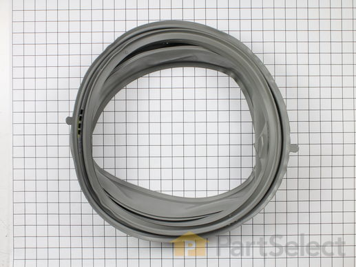
I replaced the door seal (thank you youtube videos) and all is good. The washing machine is on the upper floor in my home and could have done serious damage to the lower level if it hadn't been detected quickly.
Regards,
KevinT -
Self-balancing robot using MPU-6050HI @Henil179
I made one myself a couple of years ago, and yes, it was a fair bit of trial and error to get it working.
Of course, the gain values will be dependent on a number of factors, for example, the torque constant of your motor, the gear ratio, the mass of the robot, where your centre of gravity is located, your loop rate, and where you've located your mpu-6050.
I located my mpu-6050 over the axis at 12 o'clock near the vertical centre of my bot.What are you control variables?
I used pitch (angle of rotation around motor axis) calculated from gx, gz and tan function.
I also used pitch rate from the gyro.Are you using the onboard DSP of the mpu-6050 to do the calculations?
I had no luck with this, the mpu-6050 kept freezing up, bad clone I guess.You also have to verify the direction of rotation of your motor versus your control variables.
If you have the wrong direction, it will just run away.My gains are Kp:41, Ki:160, Kd:0.4
I started with only Kp and kept increasing the value until the system became unstable, then I backed off to a stable point.
Next, I began increasing Ki. This will bring you to steady state stability. It should balance itself when Kp & Ki.
You will likely have to reduce Kp somewhat as you move to higher Ki values, if your system becomes unstable.
Finally, I added Kd, to help it react more quickly to changes in angle.How do you change your gains?
I have a bluetooth module on mine, to allow me to send serial commands to the robot, to set the gains and other things.My robot's biggest problem is gear backlash. This generates acceleration noise as it vibrates backward/forward, balancing itself. This vibration can feedback on itself and cause instability (when you increase Kp too high). It looks like the robot has Parkinsons when this happens! :grinning:
I'd like to update my design to use a belt/gear drive or continuous rotation servo, but I haven't had a chance to get back to it.
I hope this helps.
-
Smart Speakers@ejlane Your Death star speaker sounds pretty impressive! LEDs, timer/stopwatch, impact sensor, and of course speaker & microphone, she'll be loaded. You'll have to share a few pictures. How big will it be? Which Pi fits inside it?
-
Washer & dryer monitor@CrankyCoder The code can be found on Github: Washer-Dryer-Monitor
-
Washer & dryer monitor- I used a JDY-31 module without the carrier board. The module operates on 3.3V and has a header with 0.1" spacing, perfect for my needs.
- Yes, I can share the code. There's the main sketch plus 2 libraries, one for the statistics and a modified version of the debounce library which allows me to debounce a boolean variable. The leak sensor needs this or you can get a flood of leak messages.
Where do you want me to put the code? I can put it up on Github if you like. Might be a bit much to paste here.
Regarding the rhasspy project, I hadn't heard about this, I will definitely check it out. Thanks!
-
Smart Speakers@ejlane Oh, now I get your question. Text to Speech is built into the Android OS on the phone. There is a synthesis engine which runs on the phone and generates the speech. Although it likely has networked features, for example, loading different voices.
Project Alice looks quite interesting. I'll definitely be digging deeper. I see it runs on Raspberry Pi's, maybe it will run on my Ubuntu server too. -
Smart Speakers@ejlane Yes, my speakers are best described as MQTT Text to Speech output devices. Basically, I wrote a small application which runs on a phone using MIT App Inventor. It subscribes to the Speak topic on my local MQTT broker. Whenever someone publishes to the Speak topic, it converts the text to speech. I have quite a few automations in Home Assistant which publish to Speak. I have 3 old phones set up as speakers around my house.
Regarding AI smart speakers, there is a lot of new stuff out there, with the release of tinyML.
From what I've read, the easiest type of speech recognition is "Keyword spotting" - see Edge Impulse
The next level is "Speech to Intent" - see Wio Terminal TinyML course
And the highest level is Large-vocabulary continuous speech recognition. -
Washer & dryer monitor@ejlane So far, I have a leak sensor under my clothes washer and hot water heater. I got the idea after my dish washer began leaking and damaged my kitchen cabinets. Dish washer is next...
I should clarify regarding the smart speaker. They really are MQTT text to speech speakers built from old cell phones I had laying around the house. I wrote an app in MIT app inventor. It could be expanded to play mp3 files of course and displaying images too.
I would like to create a smart speaker using Jetson Nano, but I haven't gotten around to it yet. Smart speakers might be an idea for a new thread. I haven't looked into it very deeply and could use some ideas too. :slightly_smiling_face: