Hi, i want to present you my working but not really sexy looking single cell AA battery sensor. It is as it is - under development and was just made to get some experience about power consumption and physical size.
I thought a lot about the type of battery to choose, but at the end i desisted to use an ordinary AA cell. I know about the advantages and disadvantages of different battery chemistry and types, but in the aspect of price/mA the AA battery is still the winner. Self discharge of a few years is acceptable for that type of battery.
Another aspect i followed is, just to use buy-able and assembled modules, as i don't have enough time to build my own arduino board, or battery management (step up), etc. .....
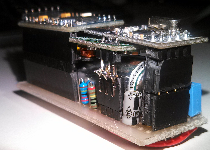
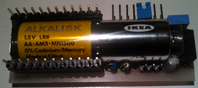
The core of the sensor is the battery itself. The components are mounted around the battery. The sensor can be completely disassembled in a few seconds, as the modules are just connected with pin headers.
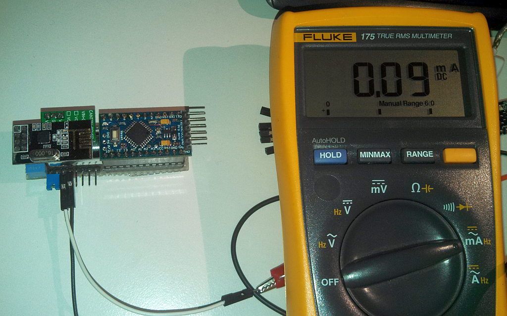
The power consumption for sleep is around 90µA, if i can believe my Fluke 175. The power consumption of normal operation and transmit i don't post here, because of two reasons:
- I was not able to get a good measurement result with a multimeter. I should integrate the consumption over time to get a real result.
- The lifetime of a sensor is dominated by the sleep consumption, not by the operating consumption (if transmission time is just a few times per hour)
There are still some improvements to do, but ehh, this is just a prototype.
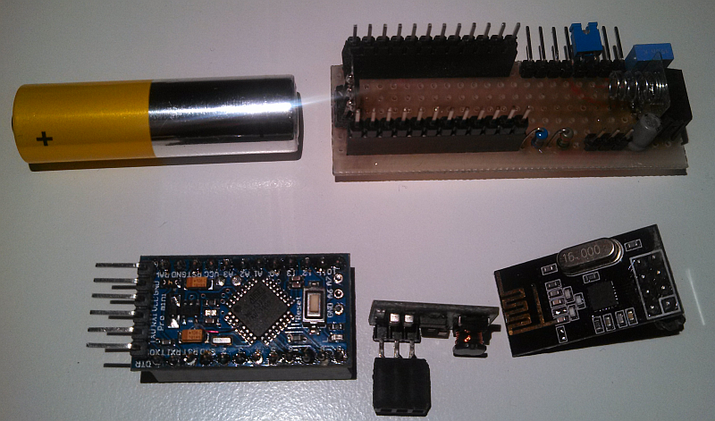
Used components:
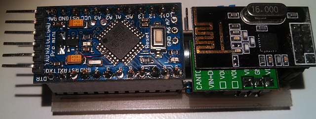
-Arduino pro mini 3.3V @ 8Mhz (mcu board)
-NRF24L01 (wireless board)
-3.3V StepUp (0.8V-3.3V from Canton electronic an ebay product link)
Modifications:
-Arduino board: Cut LED
-Arduino board: Cut LDO
-StepUp board: Cut LED
Physical dimensions (without pin headers):
65mm x 22mm x 25mm
Which values the sensor can send?
In general this is just a battery monitor, as i want to get some experience of power consumption, but the pin header is able to work with various types of sensors. I use a simple DS18B20 temperature sensor on the header pins.
Here are some pictures:
Overall view1
Overall view2
Overall view3
Overall view4
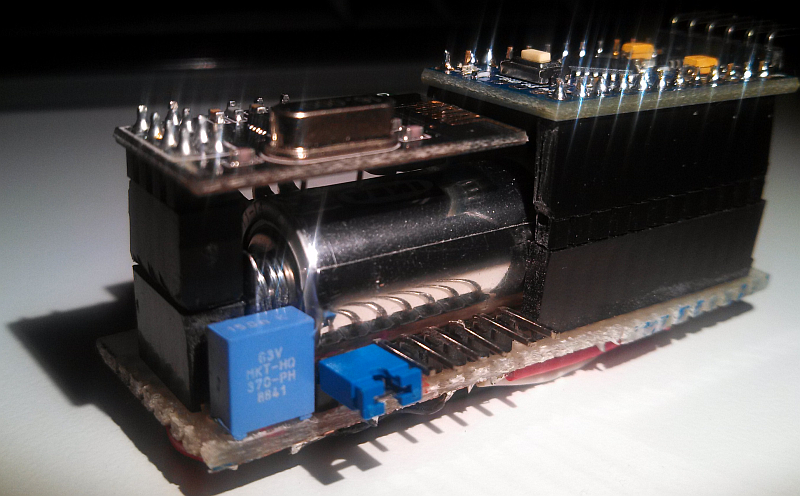
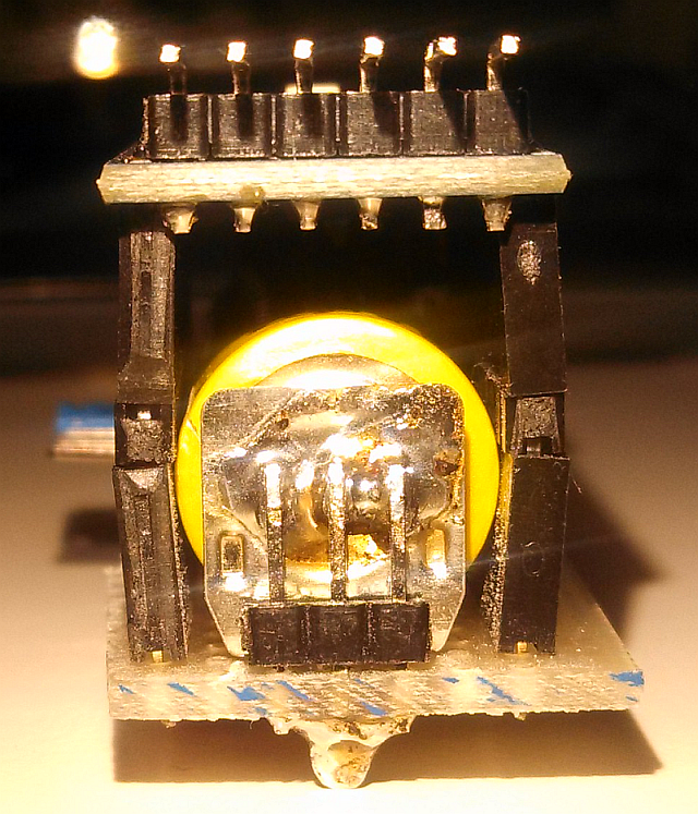
Unused space over battery, but i didn't had the correct pin headers at home "mea culpa"
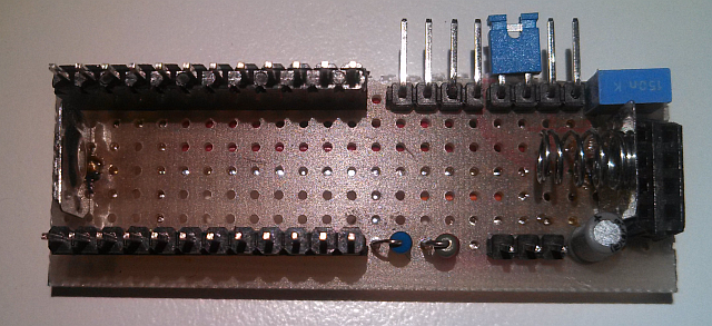
Disassembled view1
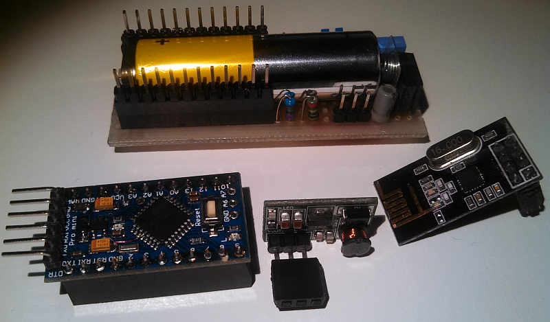
Disassembled view2
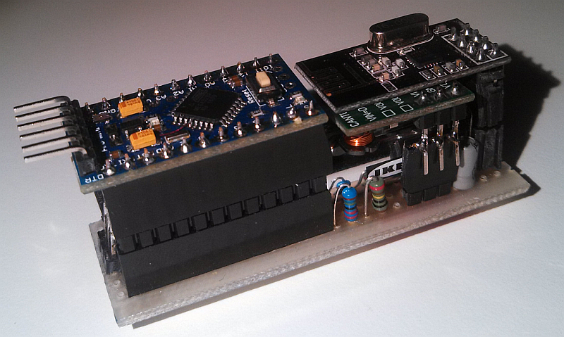
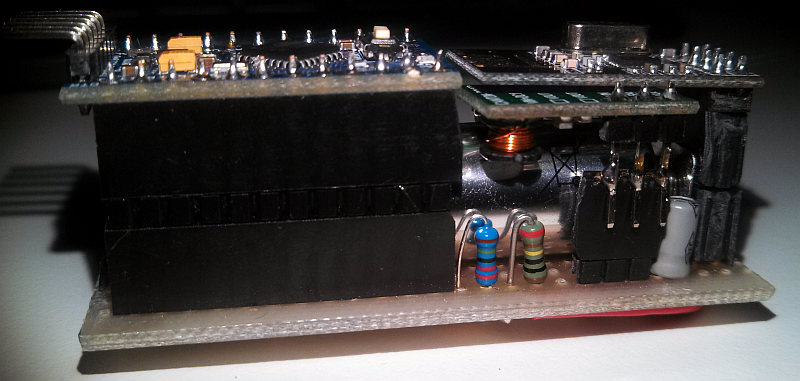
Assemble view1
Assemble view2
Assemble view3
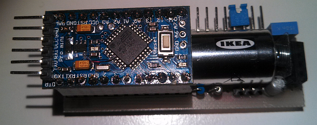
Assemble view4
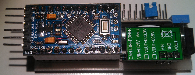
Assemble view5
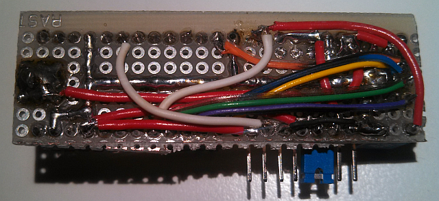
Bottom view (remember - just a prototype)
I hope i could give you some potential ideas for your own project.
Questions, suggestions, feedback, all is welcome.