Navigation

    • Register
    • Login
    • OpenHardware.io
    • Categories
    • Recent
    • Tags
    • Popular
    1. Home
    2. m26872
    3. Best
    • Profile
    • Following
    • Followers
    • Topics
    • Posts
    • Best
    • Groups

    Best posts made by m26872

    • My Slim 2AA Battery Node

      Board releases
      (other colors might be selected when ordering)

      • Version 2.0 (black) [order] Now designed in KiCad. "Final release". I'm not developing it further atm, but I know others have some projects going.
      • Version 1.4 (red) My latest version in Eagle. Known issues are wrong references due to panelization and broken circuit diagram links.
      • Version 1.2 (blue) Some less convienient placed components and the panelized verision has a faulty via.
      • Version 1.0 (green) The one described below in this first post. Working but not panelized and lacks a few features.

      Share stats and info
      The panelized versions 2.0, 1.4 and 1.2 have until today (2019-02-24) been shared 230 (!) times at boardhouse. Together with a few shares of the non-panelized version and my own orders, and the usual 3x10-11 boards/order, it means a lot of boards! Guess very few build nodes with every board, but at least the design should be well proven by now. This also means a few $ to MySensors.org, since 1 $/order will be donated. Great thanks to everyone who has orderd this board! I'll keep this share-info updated for transparency purposes. IMPORTANT: Please understand that DirtyPCBs.com is a non-profit community service, with a lot of manual support required. So please be patient and nice to their support in general. A new site is under development. Read more at their support site. EDIT 2017-06-22: Despite the new site it is still a hassle every time to get a reply from them and then the share credits. If anyone have some more info on this, please let me know.

      Introduction
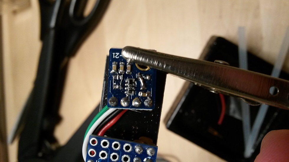
      This project describes a successor Node concept to my first 2AA battery sensor. I have combined a few simple design options to a result that I find rather useful myself and I think should be shared. The application specific sensor/-s of your own choice has to be added to this Node design, nor here any example sketches provided here except from a few links further below. I use this design for all my door and window reed switches, temperature (calibrated internal or thermistor), LDR and similar simple sensor types. But, nothing prevents the use of more sophisticated sensors like Si7021 here as well. A few links to sensor examples based on this node will be presented further down in this post.

      Features

      • Simple, in the sense that it consists of a minimum number of components and common available material.
      • Cheap regarding choice of components, assembly work effort, energy storage and power consumption (battery type and life time).
      • Flexible universal design base equipped with various sensors. PCB pads used as port connections or prototyping area for extensions.
      • Small and discrete to fit in confined spaces and to reach WAF level

      And more concrete:

      The uC
      Hardware
      A "bare bones" ATMega328p 28pin PDIP (with or without socket). Bought from here and here. My reasons to not use Arduino Pro Mini here are

      • The APM width is too big.
      • APM has no prototyping/near connection area. There's no spare pads for separate connections unless you accept to use pads connected to softwise inactive ports.
      • Radio module connection has to be manually made to the APM.
      • Low power hacks like removing power led and voltage regulator are needed.
      • Necessary support components (resistors and capacitors) are few and can easily be added to a custom pcb.

      Software
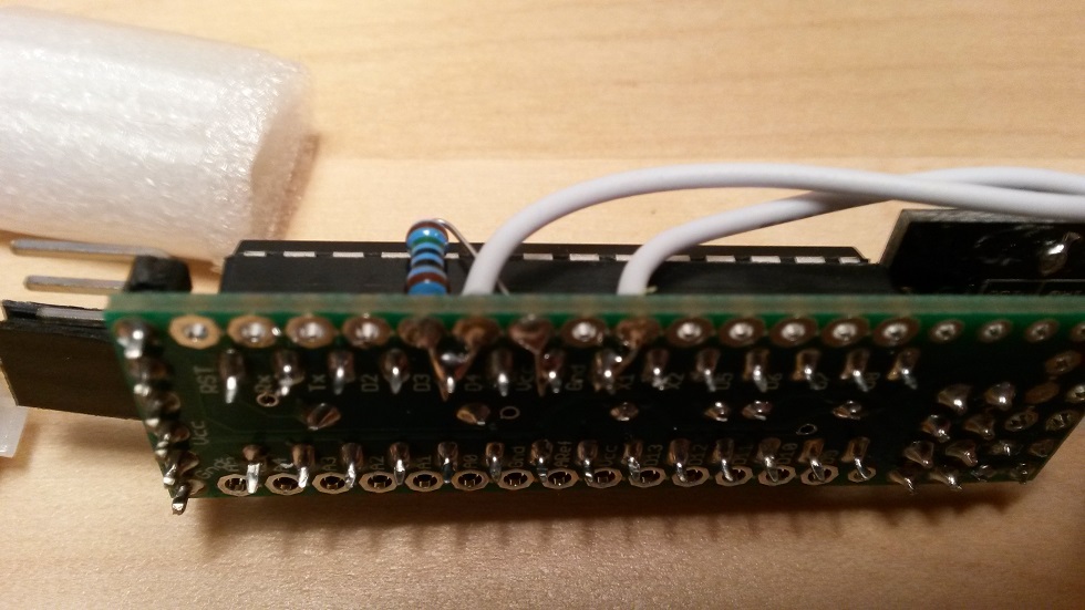
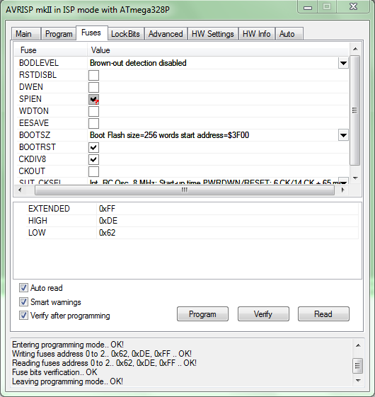
      Since I prefer Arduino IDE for programming (flash) and debugging, I need a bootloader. Bootloader instructions are found all over the internet, but here's anyway how I do it. I use this precompiled bootloader from here. It's an Optiboot with 1MHz internal clock and 9600 baud serial communication. Fuse changed to BOD disable. According to this you should use minimal startup time to reduce power in every 8s sleep cycle, but for the moment I don't care and stick to the default 65ms. I use Avrisp mkII avr programmer for fuse and bootloading similar to this procedure. Arduino as ISP, Avr/USBtiny or whatever any other should of course be just as good. Avr Studio 4.19 is a good choice for Avrisp mkII (perhaps for others too) and 4.19 is the last version before the gigantic (and for me useless) IDEs were released.
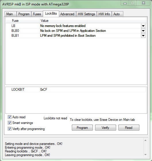
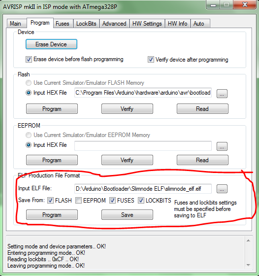
      I add this new board to my "boards.txt". Fuse settings, don't forget to set the lock bits. If programming a large batch, the ELF production file is handy.
      Here's a great tutorial for those who use Arduino Uno as ISP.
      UPDATE 1: Today (2017) a lot has happen since I wrote about this. Some things has made it easier for us. A very good selection of precompiled bootloaders is now found here at MySensors. And you don't need to (and shouldn't) mess with the boards.txt any more. Instead I recommend the installation of MiniCore to the Arduino IDE.
      UPDATE 2: There have been reported issues with MySensors 2.x freezing on SlimNodes running at 1MHz, which I've confirmed. Recommended solution when using MyS 2.x, is to use 8MHz (internal) instead.
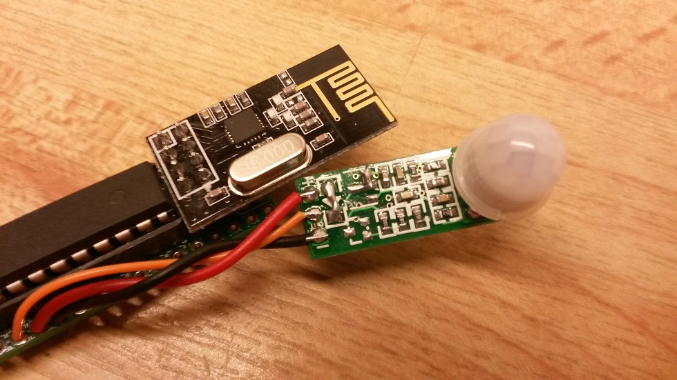
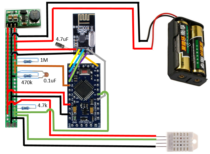
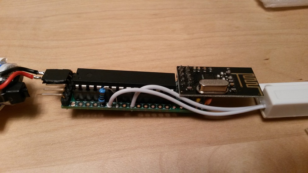
      The Radio
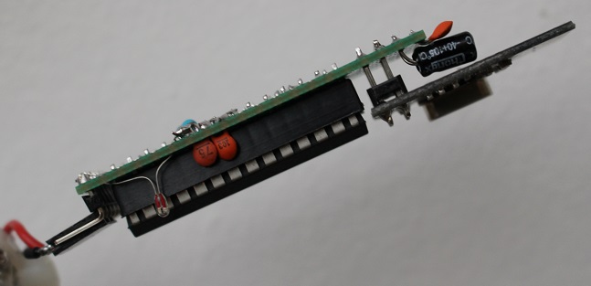
      A standard NRF24L01+ radio module is used. The width align with the AAs and no mods is needed (like with my other one). As always I try to keep the antenna part of the module free from shading metal.
      2020-12-14: On using RFM69 - here's a hint from @joaoabs at this page: I've been troubleshooting this slimnode with RFM69 radios and realized that a shunt between RFM69's DIO0 and Mega328's INT0 is required, otherwise the node will not "hear" the gateway. Even if the nrf2rmf69 board is used this shunt is required. It seems this is a re-current issue

      The Board
      At first I planned the build on a proto board, just to stick to the cheap-and-standard concept. But with today's low prices on custom made PCBs, it wasn't any longer an option. Space, quality and work effort are so much more attractive.
      Latest design files are open and available at the openhardware.io site. Please click on the image-link below to access openhardware.io where all design files such as latest BOM, kicad-files and circuit diagram (pdf) are found.
      https://www.openhardware.io/view/10/My-Slim-2AA-Battery-Node

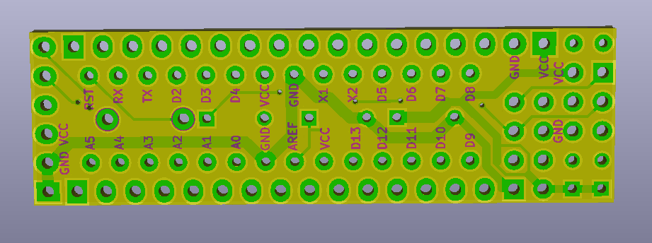
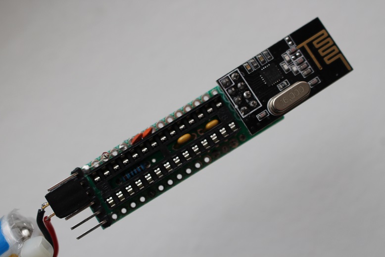
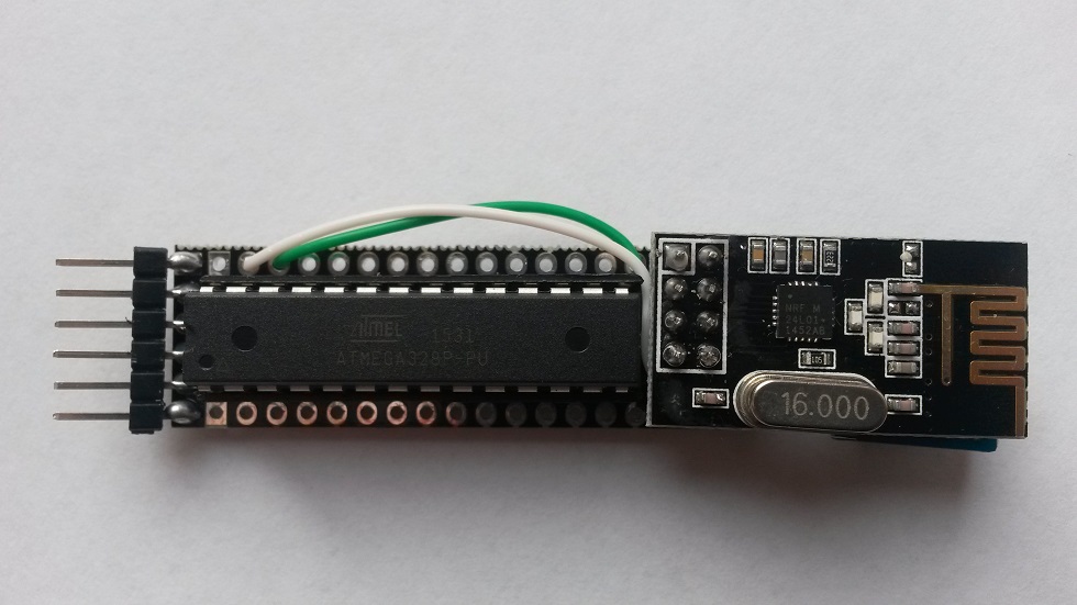
      Board (v2.0) Top Side:
      0_1455651596639_boardv2_top.PNG

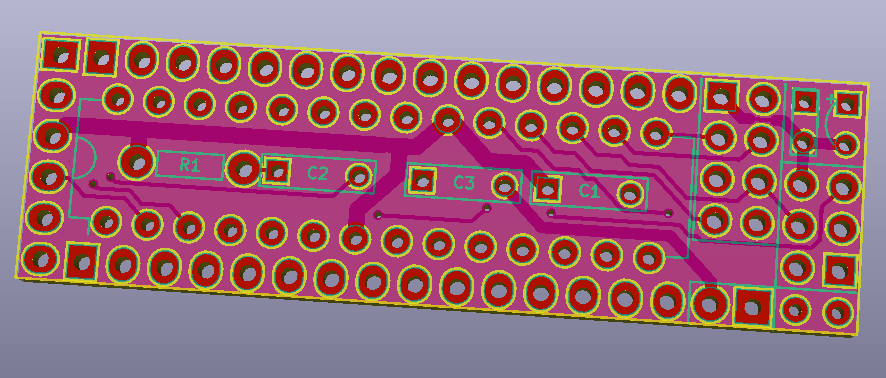
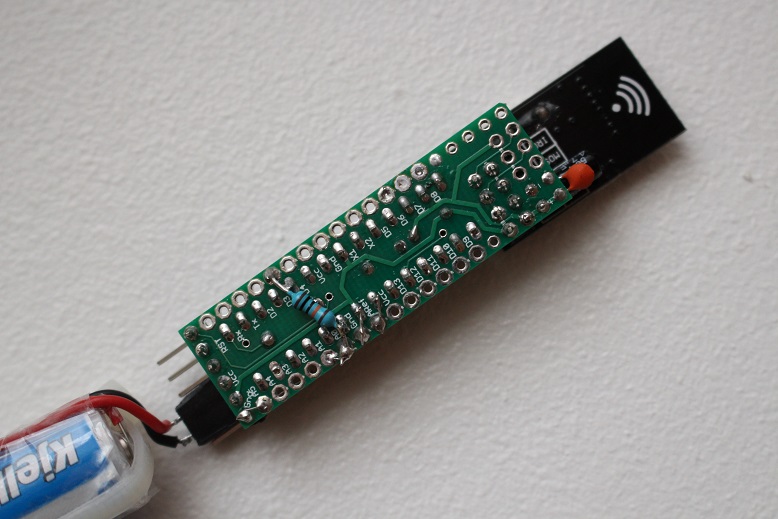
      Board (v2.0) Bottom Side:
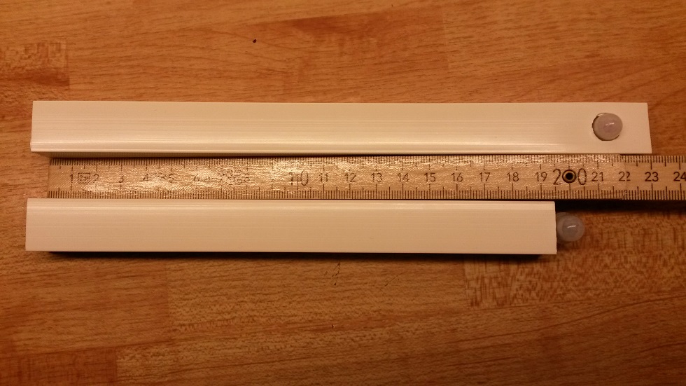
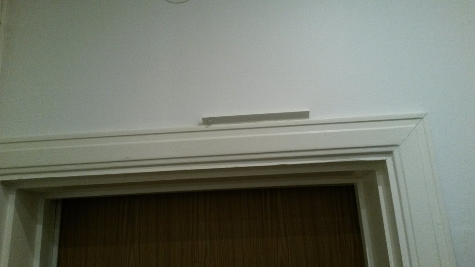
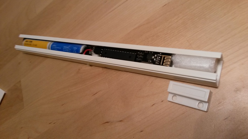
      0_1455651606026_boardv2_bottom.PNG

      The Enclosure
      UPDATE: If you dont't like my primitive casing descibed below, in this post the user @buxtronix made a nice 3D-printed case which you can find here.

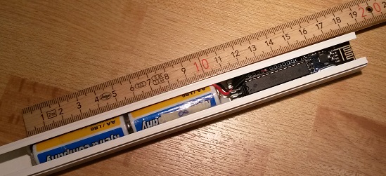
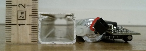
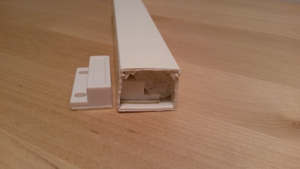
      An important overall part of this design idea was to align minimum dimensions of the components and get rid of "expensive" parts like battery holder. It turn out (see below) that the enclosure's functionality as battery holder wasn't needed even though it was the initial idea. The cable duct case has been discussed earlier, but rejected by some due to lack of ways to seal the endings. I still haven't the perfect solution, but I've since many years simply used (cheap) white tape. With some care it looks ok, and still does 5-10 years later. There are often proper terminators/endings to buy, but for some reason to unrealistic high prices.
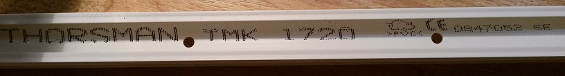
      I used this cable duct with the dimension 17x20mm. Unfortunately it turned out that this particular type I used (Thorsman TMK T20) is now "professional grade" and dimension 17x20 is no longer very commercially available for consumers (here in Sweden at least). Eg. to get it, you have to pay >5$/m from places like this or buy it in bulk (50m) from a professional store (preferably as a professional with discount). The 50m bulk batch will give you 263 sensor nodes of standard length (19cm).
      Standard consumer dimension cable duct is e.g. 15x15mm from what I've seen. It'd be nice to design a 2AAA node in that one. If only there is a thin radio module? (Future project.)
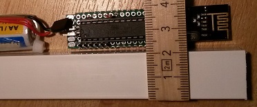
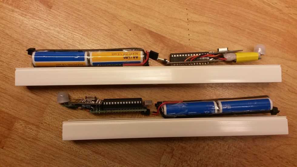
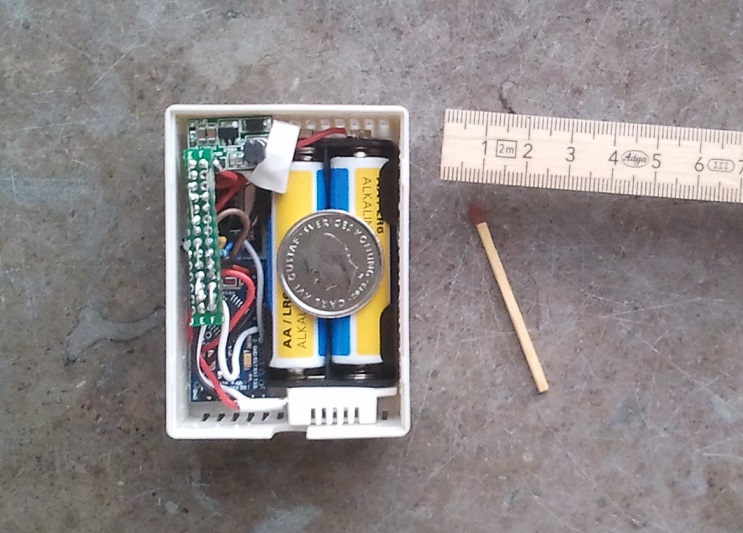
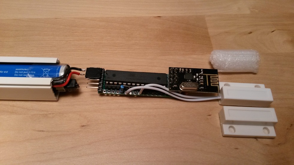
      box1.jpg box2.jpg box3.jpgbox4.jpg

      The Battery pack
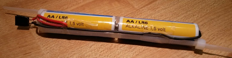
      Easy home made 2AA battery pack. Maybe it looks more demanding and time consuming than it is. (Usually its the other way around in my experience.)

      1. Start by taping the two (connecting) batteries together.
      2. Prepare the wires and make a small bun at the battery connecting ends.
      3. Attach the wires with tape.
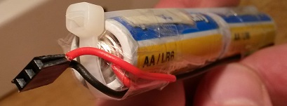
      4. Tighten the cable ties and carefully note
      • that the wires are pressed to make good contact with the battery poles
      • how the cable tie ends must be placed to not steal lateral space
      • that the wire from the bottom must be routed near the cable tie to not steal space.
      1. Make the pack more rigid by taping one or two times around at the top, bottom and middle.
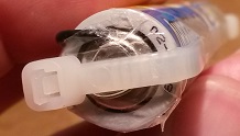
      2. Trim wires and solder the female connector. If desired, leave at least a small part of one wire naked for current measurements.
        A battery change is done fast when cables a already made (use solid wires that preserves its shape). So why pay for a battery holder when you can remake a pack with fresh batteries in 1-2 min and your low power sensor will live 5-10 years before anything needs to be done?
        bat1.jpg bat2.jpg bat3.jpg

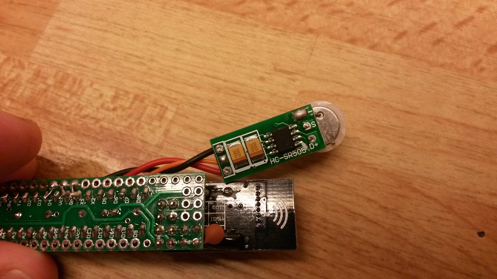
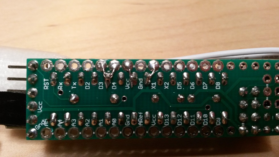
      The Interface/Connections
      Convenient there's the 6 pin standard serial interface exactly like on the Arduino Pro Mini. Perhaps it's mirrored here, but I think everybody double checks Gnd and Vcc before connecting. The Vcc and Gnd pins also serves as a connector for the battery pack. (CTS is connected to GND on the PCB.)
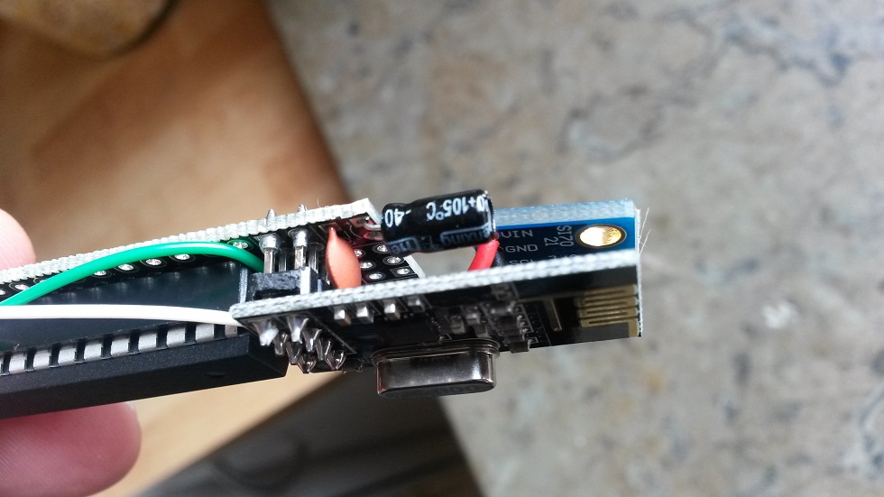
      "Under" the radiomodule are pads for the ICSP pins. The idea was to have a socket for the radiomodule instead of the "expensive" 328p socket and still have easy future access to the SPI/ICSP interface. Perhaps not very useful. But nice to have Gnd and Vcc in this end of the board for general purpose.

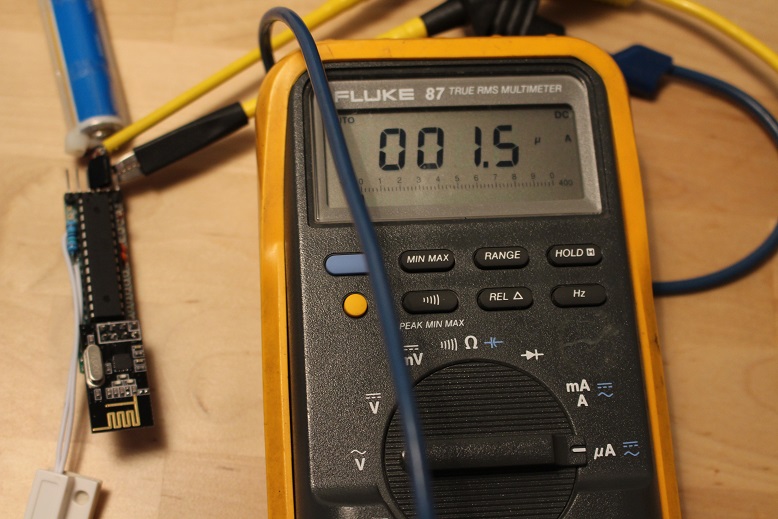
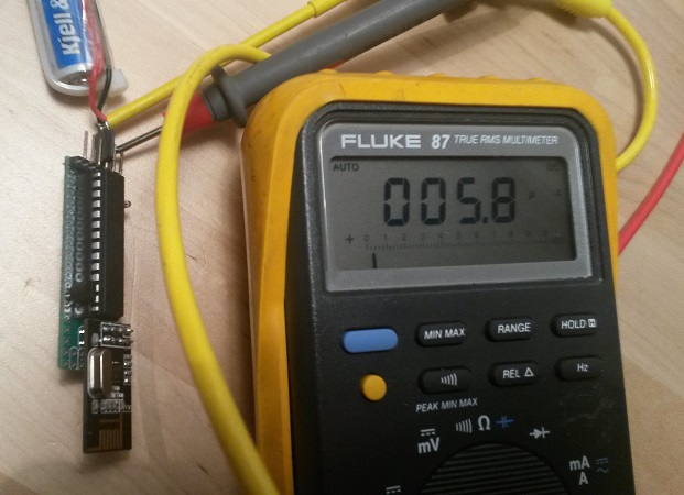
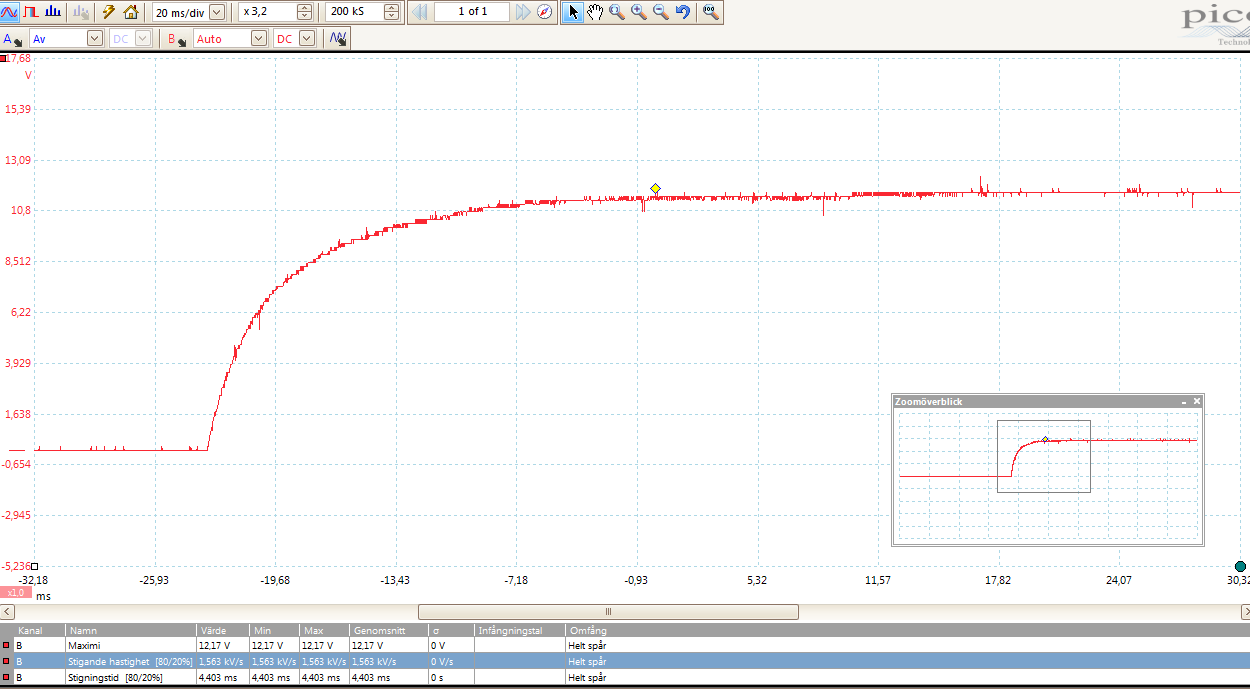
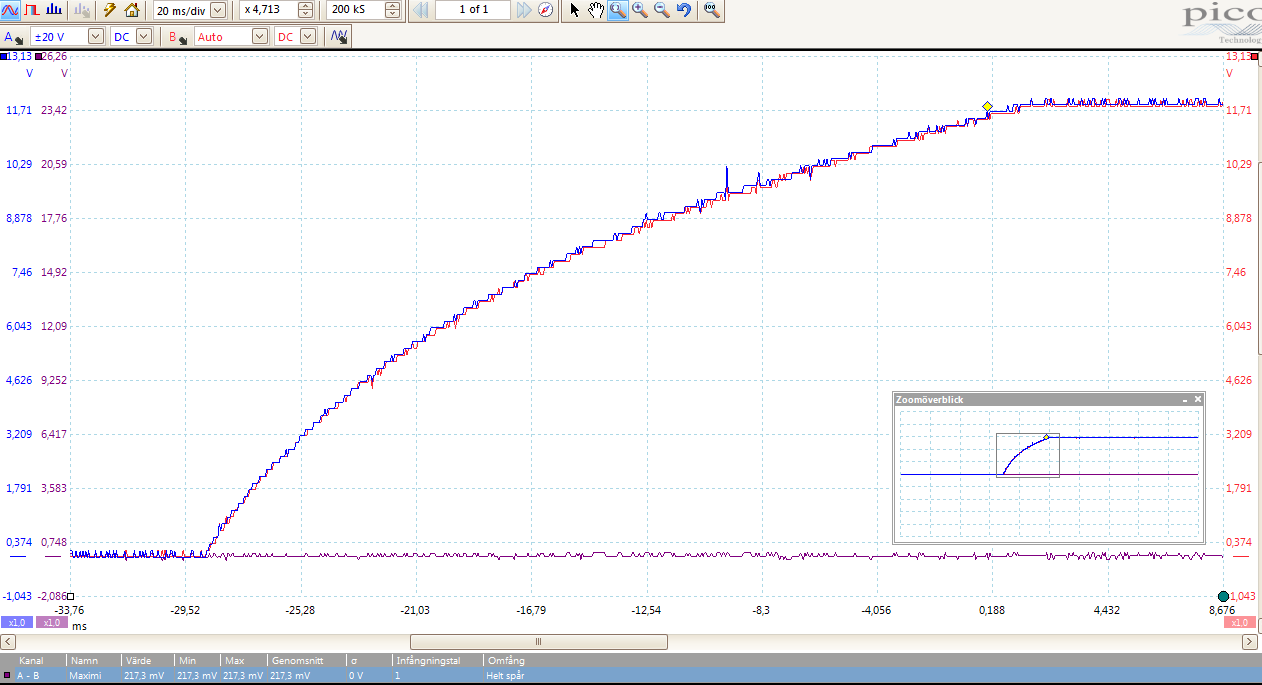
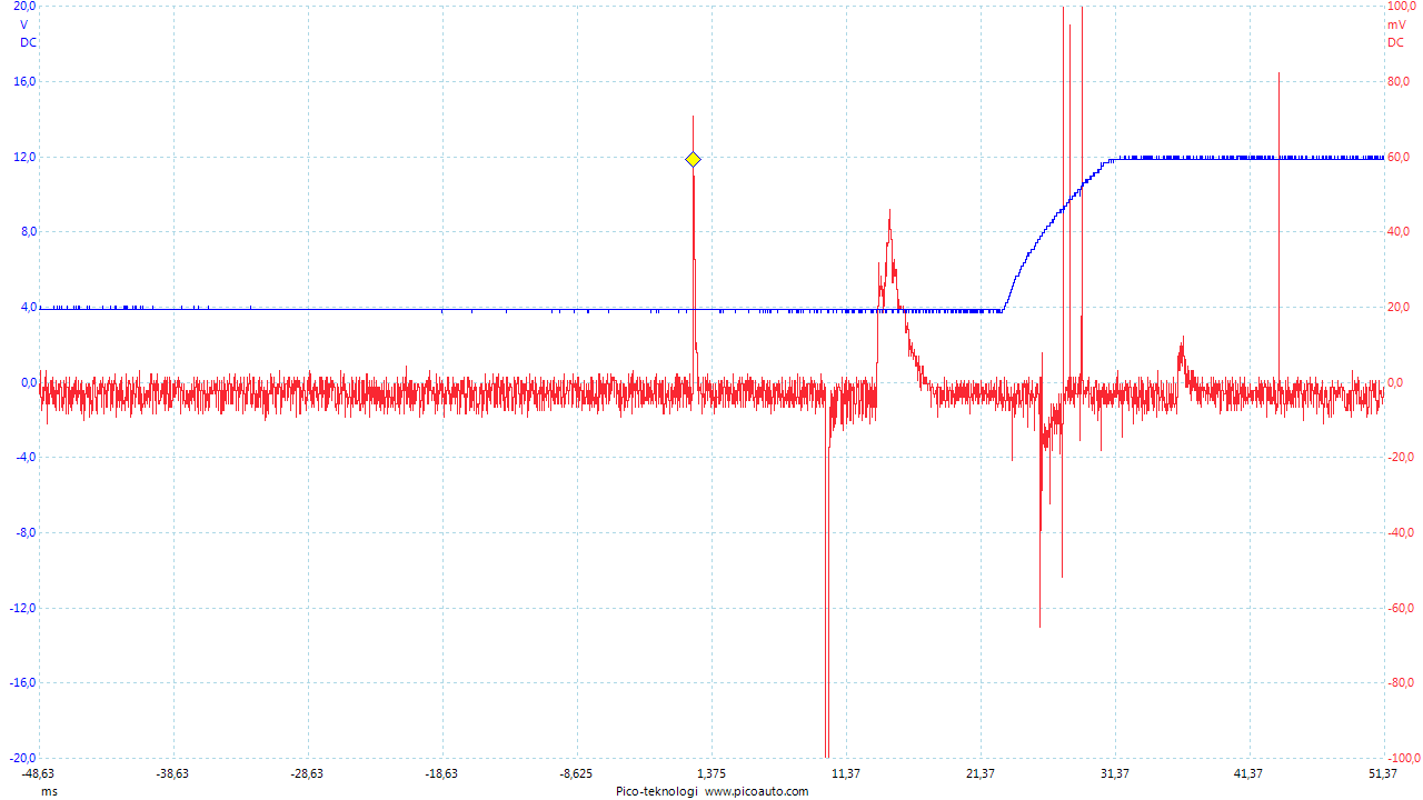
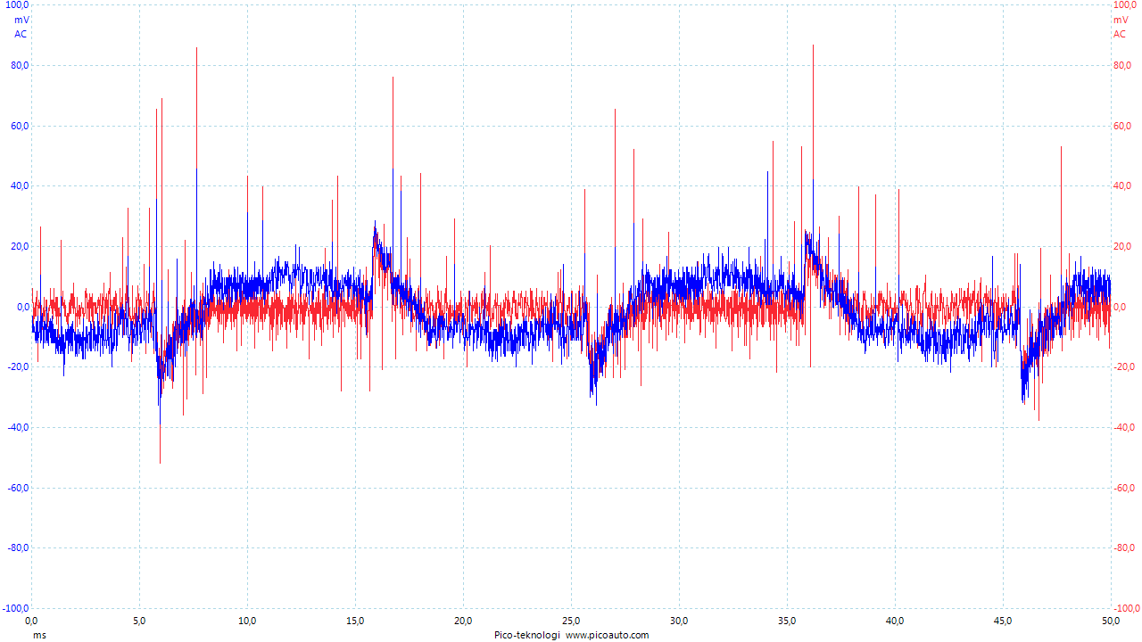
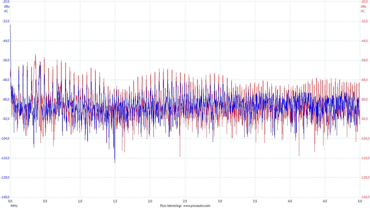
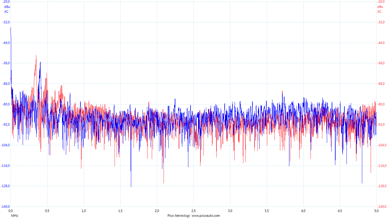
      The Sleep Mode Power Consumption
      I measured the sleep mode current draw to be 1.5uA when it's set to interrupt wake up and 5.8uA when it's set to timer wake up.
      power1.JPG power2.jpg

      Sensor Examples and more
      Reed Switch Sensor: post 116
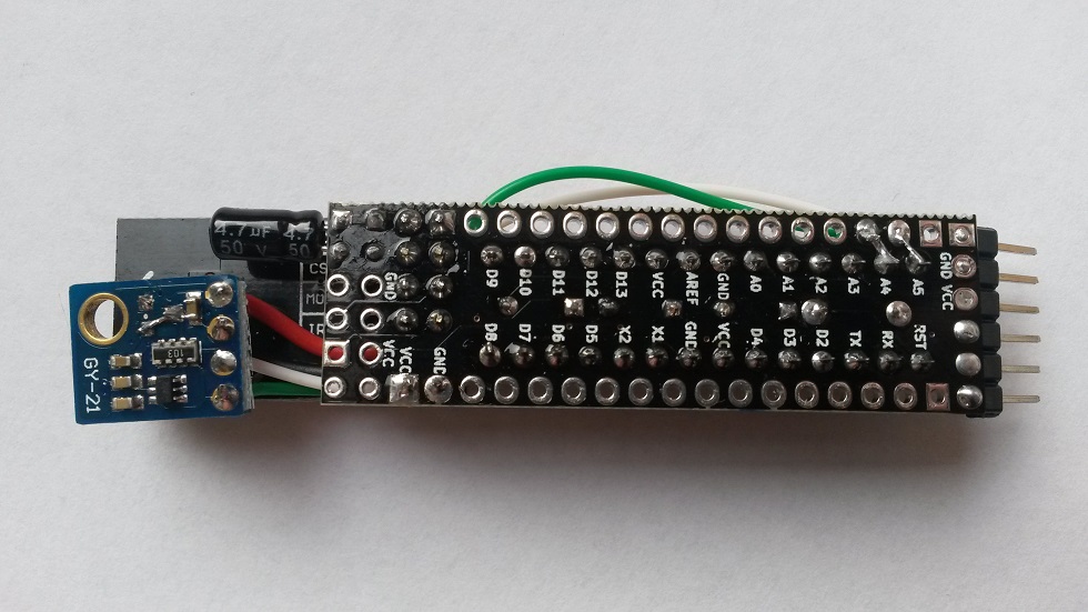
      Humidity Sensor: Slim Node Si7021 sensor example
      Motion Sensor 1: Slim Node as a Mini 2AA Battery PIR Motion Sensor
      Motion Sensor 2: Slim CR123A (2AA) battery node..
      Scene Controller: Slim Node scene controller/ keypad
      (work in progress to collect more examples here)

      Not Sensor exemples, but some nice to see "node variations" from @AWI:
      Here (post 88) and here (post 233). And now there's also @AWI 's My Slim 2AA Battery Node Tools.

      Still not "slim" enough? Check out Very Narrow and Minimal Switch Node ! by @GertSanders

      And also, there's this 5V-slim-node a 5V-slim-node mod by @Soloam

      Feature Requests
      Here's a collection of suggestions and development ideas for future versions of the board (or other parts). If anyone else make their own board where some of this is included, I'd be happy to reference it from here.

      • Pin labels/references also on board top side.
      • Turn the nRF footprint to make the assembly shorter.
      • Make the board suitable for the nRF SMD version.
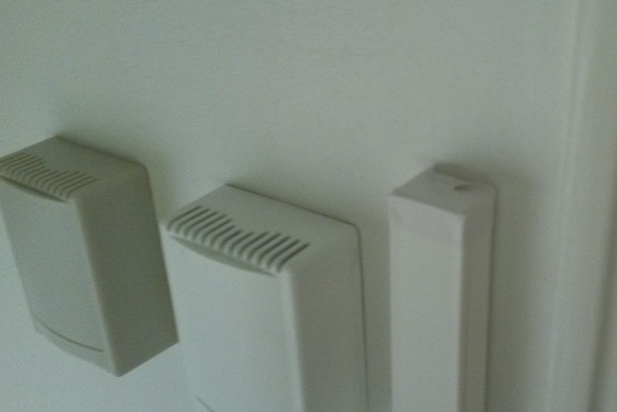
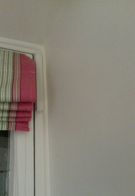
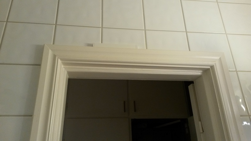
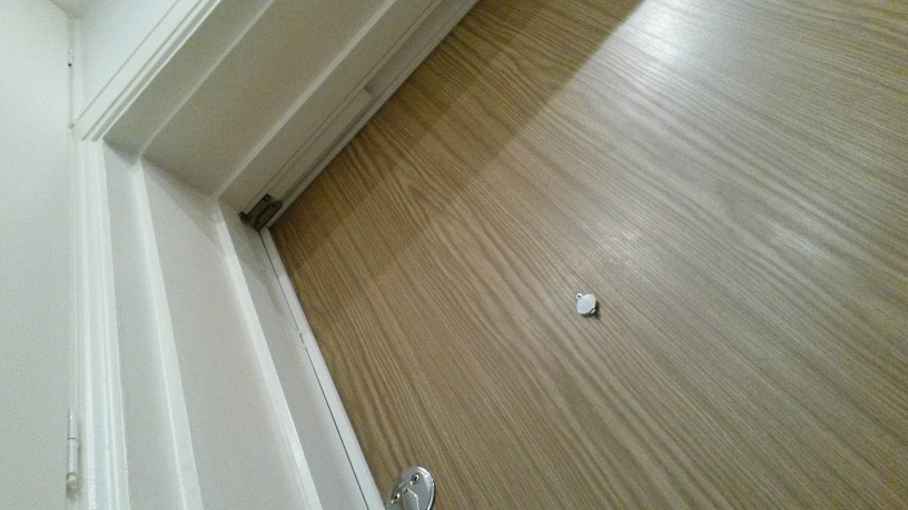
      More Pictures
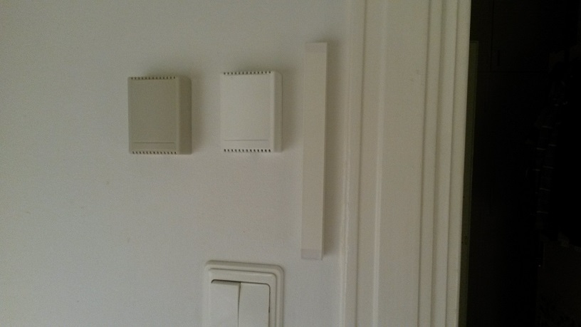
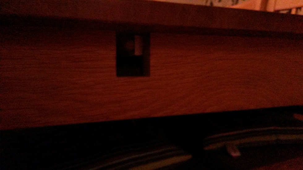
      Some photos. First a comparison next to My (old) 2AA battery sensor, one painted and one not. (Note the high WAF of the colour even without the paint.) Then some placement examples. Reed switch nodes for all my doors and windows are my first priority.
      20150901_220448.jpg 20150901_220505.jpg 20150901_220659.jpg 20150901_220847.jpg 20150901_220948.jpg IMG_2065.JPG IMG_2063.JPG IMG_2064.JPG

      posted in My Project
      m26872
      m26872
    • My look at a cheap 12V power supply

      Summary
      This post shares my own non-professional evaluation of the 230Vac to 12Vdc cheap Chinese converter module (aka Switched Mode Power Supply, SMPS) called YS-12V400-B. It's now rather rare, but instead replaced by the very simmilar HX-12V400X which is found easily on Aliexpress by searching "12V 400mA power supply").
      This is not a thorough test. I've looked documentation, load- and temperature- and startup characteristics and did some simple noise filter tests.
      I will not give a straight answer to your question "is it safe?", instead I hope to provide information enough for you to draw your own conclusions.
      0_1458237480097_bild1.png 0_1458237502938_bild2.png 0_1458237519485_bild3.PNG 0_1458237541436_bild4.PNG

      Introduction
      I first saw this module from @axillents post in another thread . I bought a batch almost a year ago , but haven't had the time to look at it until now. Now, a quick look at Ali tells me that it has become rather popular at a few sellers, but there's still no reviews to find. Some user comments I found here .

      There is a new variant of the YS-12V400-B called HX-12V400X where the first (of few?) differences I can see from photos is that a clear blue (XY-grade?) high voltage capacitor has replaced a flat dark green one. Also there's an anti-creepage hole removed near mains input, where a pad has been changed instead. The HX-12V400X seems to be the most common one available on Ali and should probably be better to buy. The one I bought is gone of course. Here's one of few old ones, though.

      Like everybody else, I'm looking for a small supply for my projects. The HLK-PM01 is bulky and I don't see a great value of the enclosure when the bare 230V pins are still there. Also, I care about safety and would not feel comfortable with this kind of unknown quality supply in a class III appliance device where secondary side is touchable. I'd prefer a metal case (class I) for safety earthing and fire protection, but it's not always very economical or practical so I then put my trust in good fuses, insulation (class II) and protective functions.

      Some reasons for me to favour 12V in front of 3.3V and 5V are:

      • A strive to standardize parts, reuse and keep my assortment of parts as lean as possible.
      • Easily converted to 5V or 3.3V with linear regulator where the extra converter's power supply ripple rejection (PSRR) is desired.
      • I don't mind the small extra loss or heat due to 5V or 3.3V conversion.
      • Flexible in respect of component selection and circuit design. Particularly when dealing with electromechanics like relays and servos.
      • Preferable if one wish to distribute power further without to much loss and voltage drop.
      • Less current and smaller components.
      • Works with Arduino Pro Mini internal regulator. (Note that some APM clones can't handle 12V.)

      Since the HLK-PM01 has become our reference device after the famous lygte-info.dk review , I've been thinking that some kind of testing and closer look needs to be done before using ANY kind of Chinese SMPS. I may not have all equipment or skill, but with a small effort a lot can be done. At least to reassure myself that the device is useable (or not). Still, I don't consider anything but certified products as "safe".

      Documentation
      Official specifications are hard to find and very limited as usual when it comes to these cheap Chinese products:
      Dimensions: :4 x1.5 x 1.8cm
      Input voltage:AC 90V~240V 50/60HZ
      Output voltage:DC 12V (±0.2V)
      Output Current: 400mA
      Output power: 4.8W
      90V~240V AC Input,Constant 12V DC Output ,Ultra small,Precision
      Application: the power adapter,industrial equipment,microcontroller,LED lighting power supply, etc
      AC input:Does not distinguish between live line and null line.
      Protection functions:YES
      Shortage Protection:YES
      Temperature protection:YES
      Overcurrent protection:YES

      A look through the magnifier reveals the controller IC name "THX208", which then provided a pretty good datasheet . (Of course you might need a translation tool, but after that it's very readable). It turns out that the power supply module we're studying is designed very close the provided typical circuit:0_1458237662241_BILD5.PNG

      ...but with a few simplifications (the low cost device is made even cheaper?). One is that the Y suppressor capacitor is omitted, great for safety but not so great for EMI suppression. Another is an inductor at primary side (simple line filter?). Bad EMI to expect from this then? Maybe, I don't have any tools or knowledge about EMC, but we'll see if there're any signs of this later perhaps... The HLK-PM01 EMC review is my reference of about what to expect.

      Visual check
      It looks OK, without any apparent insane design choices. Creepage distance around mains input is as usual unnecessary small. It's barely the required 3mm so keep it away from polluted environment and have good fuses before it. The primary-secondary distance looks good, with only the transformer and opto-coupler interconnecting.

      Load test measurements
      Test input voltage: 239Vrms
      No load output voltage: 11.85V
      No load input current(AC): 2.4mA
      Load test presented below was conducted by applying a 150uF cap together with a few different resistive values. Different cap values (0-2mF) had a small impact on latest half of the output voltage rising slope, nothing else. 150uF was left through the rest of the tests to simulate a realistic value.
      0_1458237761354_BILD6.PNG

      Maximum overload: n/a
      As the current/load increases above nominal current 400mA, the controller effectively decreases voltage to keep within constant max power 4.8W. At 185% nominal current, it starts cutting off the output repeatedly at 2-3Hz.

      Output voltage ripple
      At no load: 52mVrms
      0_1458237784176_BILD7.PNG

      At nominal load: 76mVrms
      0_1458237794079_BILD8.PNG

      Switch frequency: 40-60kHz (increasing with load)
      Half load:
      0_1458237804806_BILD9.PNG

      Full (nominal) load:
      0_1458237814148_BILD10.PNG

      Startup time tests showed variations depending on line phase, load/load-type and unknown factors. Numbers presented below are averages from a lot of sample startup tests and typical characteristics are shown. A current probe (100mV/A) is used on AC input wire.
      Controller startup time (from power-on until the beginning of output voltage increase): 15-20ms
      0_1458237833269_BILD11.PNG

      There also a strange phenomenon where startup time sometimes is ~100ms. I haven't been able to figure out when or why it happens, but there seems to be some correlation with high loads, load time and frequent startups.
      0_1458237845846_BILD12.png

      Voltage rise time, no load: 7ms
      0_1458237858838_BILD13.PNG

      Voltage rise time, full load: 15-20ms
      0_1458237870526_BILD14.PNG

      Voltage rise time, 1.5mF load: 30ms
      0_1458237881501_BILD15.PNG

      A quick reconnect results in a little faster uptime but no notable difference in inrush current. The on-board output ballast (LED) de-energizes the load capacitor pretty fast.
      0_1458237893111_BILD16.PNG

      Inrush current and fuse value
      Since using a fuse at the input to this supply is a very good safety practice, we need to know the expected current characteristics. Especially during startup when there's high currents even for moderate loads (link) . I had some theories and calculations posted in the "Safe in wall..."-thread . From the measurements presented in this post it looks that I was rather correct in my assumption regarding the first inrush current, but rather wrong about the succeeding one.
      The first 1-2 peaks when energizing the filter cap has very high current, but very short duration (<1ms) which won't melt a normal fast fuse. Sometimes this first quick inrush impulses are several due to bouncing connectors and when in the line phase it connects.
      0_1458237909724_BILD17.PNG

      The second one though was not as I thought. It was not related to load or output voltage raise. It was actually very unpredictable and could even superimpose on the first filter inrush current. In total worst case then there is a <1ms peak at >10xIn followed by 3-4ms at ~0.4A. If I've read IEC 60127 -1 and -2 correct, the fuse must have pre-arcing at 2xIn, meaning 0.2A fuse is on the edge and 0.3, 0.4 or even 0.5A would probably be better. I think 0.5A is the most common and easiest to find. The disadvantage with a too low value is wear and frequent spurious fuse blows with the risk of user neglecting real issues instead.
      Since there's completely silent on the secondary (output) side, my guess is that this "second inrush" power is dissipated by the controller for some reason. - If an expert or anybody knows more about this or have another guess your welcome.

      Operating temperatures
      Max temperature at nominal load: 65'C
      A maximum and stable temperature was reached after ~5min and remained the same until the test stopped after 60 min. The controller IC and the rectifying diode heats up pretty fast and to the same temperature. A litte faster and 1-2'C more for the controller. As the time goes the transformer will heat up as well. Probably partly because those hot components on each side.
      0_1458237928232_BILD18.jpg
      0_1458237937791_BILD19.jpg

      Max temperature at "overload": 75'C
      Because of the controller overload protection, the supply can't be overloaded in the true meaning. Here's the study of high-current-low-voltage condition right before it enters protection mode with repeatedly switching on and off, and everything cool down. Just like the nominal case, the temperature stabilizes fast and stays there. The most notable difference in this case is the rectifier diode gets hotter than the controller (~5'C).
      0_1458237951780_BILD20.jpg
      0_1458237962058_BILD21.jpg

      Noise
      EMI is another great concern regarding these kinds of cheap Chinese power supplies. The HLK-PM01 EMC test confirms this and don't expect the YS-12V400-B to be any better. I don't have the equipment or knowledge to test EMC/EMI, but I have my Picoscope and two AC current probes I can use to study the device at different loads and so on. I assume this can be used to give an idea of what to expect.
      First its easy to see from the startup measurements above that there's more noise during the rise of output voltage. There's also a correlation between increased load and increased current noise.
      Here's a comparison between low load (280ohm) and nominal load (30ohm) in time domain (Blue=I_in, Red=I_out):
      0_1458237977659_BILD22.png
      0_1458237997082_BILD23.png

      and in the frequency domain:
      0_1458238013607_BILD24.png
      0_1458238024566_BILD25.png

      As an experiment I applied the line filter from a good quality 300W old computer PSU. It's actually a two stage filter where one is the common type built into the power cord socket.
      0_1458238519130_BILD26.PNG

      Here's it in action for nominal load (30ohm) (Blue=I_poweroutlet2filter, Red=I_filter2SMPS):
      0_1458238108998_BILD27.png

      Here's a comparison between nominal load (30ohm) and low load (280ohm):
      0_1458238119075_BILD28.png
      0_1458238130224_BILD29.png

      So the conclusion here is that the filter is working, but it's not nearly as effective as using a low load.
      If you intend to use any of these supplies at 400mA or perhaps even at 50% continuously, it'd probably be recommended to use one of the models with EMI filter.

      Conclusion
      A few aspects of the supply module have been studied, no issues have been found and it corresponds to the found documentation. EMI is probably OK if the load is small.

      Design Example
      Here is a recent design example with this module:
      https://www.openhardware.io/view/47/My-MySensorized-Wall-plug

      posted in Hardware
      m26872
      m26872
    • Slim Node as a Mini 2AA Battery PIR Motion Sensor

      After reading about @AWI 's C123A battery based slim PIR sensor, I've finally have had time to play with the mini PIR motion sensor a little myself. Luckily I found a little for me easier, working design which I believe will satisfy my own needs sufficiently. It's basically just the mini-PIR HC-SR505 with its diode and voltage regulator removed, attached to the Slim Node and with simple but suitable sketch.

      Conclusion from my playing with the HC-SR505 was

      • power consumption was identical to mesurements by AWI, 46uA (no movement) and 62uA (movement) . Removing the 7133-regulator did not affect anything significantly due to its very low quiescent current (see datasheet, perhaps useful in some other project?)
      • it's flexible regarding output (load) impedance and load will not affect sensitivity, no need for pull-up/down, filter, etc
      • the supply voltage range with diode and 7133-regulator removed was great. Flawless results with only one AA (1.6V), and I saw no point to go lower.
      • it's very supply noise sensitive and will false trigger on almost anything. Any kind of switching boost (voltage step-up) regulator made it trip continuously. (Found some differences between small and big 3.3V-step-ups btw). Any activity on a nRF connected to same supply would also generate a false trip.
      • the ~3m max range or sensitivity doesn't seem to be affected by voltage level or noise.

      I'm not going to try some hw-filter to get rid of the nRF false trip issue. I think we're all aware of the very hard task to to this when it comes to the nRF itself. For my need it's good enough to just dealing with it in the sketch.

      Two sensor nodes, one shorter enclosure with the PIR peeking out and the other one with a traditional oriented fit. I resoldered one of the three PIR legs so they're all on the same board side to facilitate the angled position.
      20160102_001318.jpg

      The sketch
      The sketch (and this sensor) is not intended to reside in a busy place or work as presence sensor. It's better as a guard, alarm or notification in a low frequency/activity environment. One obvious reason is that the range is not very impressive (max 3m). Then, with this sketch, the controller will just be informed when motion starts. After that, there's no way for it to distinguish absent motion from continuous motion. My reasons for this are (1) it's ok for my application (2) simple (3) save battery and (4) to overcome the false trip problem.

      /**
       * EgSlimReed2
       * Sketch for Slim Node and HC-SR505 based motion sensor. 
       * Inspired by:
       * - MySensors motion sensor example: http://www.mysensors.org/build/motion
       * - AWI's CR123A based Slim Node motion sensor: http://forum.mysensors.org/topic/2478/slim-cr123a-2aa-battery-node
       *
       * Created by m26872
       * Documentation: http://forum.mysensors.org...
       *
       * This program is free software; you can redistribute it and/or
       * modify it under the terms of the GNU General Public License
       * version 2 as published by the Free Software Foundation.
       *
       *******************************
       *
       * REVISION HISTORY
       * Version 1.0 - Test to if node can operate in some way dealing with the Pir extreme sensitivity to noise on Vcc.
       * Version 2.0 - First "production node". "Inactivity day counter" introduced.
       * 
       * DESCRIPTION
       * This sketch will only send trips as "1" to the controller. It's up to the controller to deal with the info. 
       * The motion node will not notify controller when resets back to low state and is ready for a new trip. In reality 
       * this is ~10s. And EVEN IF motion is detected continuously, there will be no new trip until motion has stopped for ~10s.  
       * The HC-SR505 is very noise sensitive and will trigger spuriously for almost any activity 
       * on Vcc (test thoroughly). To run the HC-505 at low voltages (tested flawlessly down to 1.6V), 
       * the 7133-reg and diode are removed (and possibly increase the sensitivity even further). 
       * Solution is to deal with it by interrupt type, check which source, block by sleep time etc.
       * 
       * HC-505 output connects to MOTION_INPUT_PIN (here D3) without any supporting component. Input pull-up disabled.
       * Every 24 hrs without trip, increments a counter and after "BATTERY_REPORT_DAY" counts a battery report will be sent as a heartbeat signal.
       * Else a battery report will be sent after every "BATTERY_REPORT_BY_IRT_CYCLE" motion trips.
       *
       */
       
      #include <MySensor.h>
      #include <SPI.h>
      #include <Vcc.h>
      
      //#define DEBUG
      
      #define NODE_ID 14  // Use static Node_ID  <<<<<<<<<<<<<<<<<<<<<<<<<<<<<<<<<<<<<<<<<<<<<<<  //14 var senaste "slim-PIR"-id 
      #define SKETCH_NAME "EgSlimPIR2"
      #define SKETCH_VERSION "2.0 2016-01-01"
      #define CHILD_ID 5
      #define MOTION_INPUT_PIN 3
      #define BATTERY_REPORT_DAY 2   // Desired heartbeat(battery report) interval when inactive. 
      #define BATTERY_REPORT_BY_IRT_CYCLE 10  // Make a battery report after this many trips. Maximum report interval will also be equal to this number of days.
      #define ONE_DAY_SLEEP_TIME 86400000
      #define VCC_MIN 1.9
      #define VCC_MAX 3.3
      
      #ifdef DEBUG
      #define DEBUG_SERIAL(x) Serial.begin(x)
      #define DEBUG_PRINT(x) Serial.print(x)
      #define DEBUG_PRINTLN(x) Serial.println(x)
      #else
      #define DEBUG_SERIAL(x)
      #define DEBUG_PRINT(x) 
      #define DEBUG_PRINTLN(x) 
      #endif
      
      int dayCounter = BATTERY_REPORT_DAY;
      int irtCounter = 0;
      
      
      bool interruptReturn = false; // "false" will make the first loop disregard high output from HV-505 (from start-up) and make a battery report instead.
       
      Vcc vcc;
      MySensor gw;
      MyMessage msg(CHILD_ID, V_TRIPPED);
      
      void setup()  
      {  
        DEBUG_SERIAL(9600);
        DEBUG_PRINTLN(("Serial started"));
        delay(100); // to settle power for radio
        gw.begin(NULL,NODE_ID);
        pinMode(MOTION_INPUT_PIN, INPUT);
        digitalWrite(MOTION_INPUT_PIN, LOW);    // Disable internal pull-ups
        gw.sendSketchInfo(SKETCH_NAME, SKETCH_VERSION);
        gw.present(CHILD_ID, S_MOTION);
        DEBUG_PRINTLN("Warming and blocking PIR trip for 20s.");
        gw.sleep(20000); // Wait until HC-505 warmed-up and output returned low.
      }
      
      void loop() 
      {
        if (interruptReturn) {	// Woke up by rising pin
      	gw.send(msg.set("1"));  // Just send trip (set) commands to controller. (Let controller reset and decide what to do with it.)
      	irtCounter++;
      	if (irtCounter>=BATTERY_REPORT_BY_IRT_CYCLE) {
      		irtCounter=0;
      		sendBatteryReport();
      	}
        }
        else { // Woke up by timer  (or it's the first run)
      	dayCounter++; 
      	if (dayCounter >= BATTERY_REPORT_DAY) {
      		  dayCounter = 0;
      		  sendBatteryReport();
      	}
        }
        
        gw.sleep(3000);  // Make sure everything is stable before start to sleep with interrupts. (don't use "gw.wait()" here). Tests shows false trip ~2s after battery report otherwise.
      
        // Sleep until interrupt comes in on motion sensor or sleep time passed.
        interruptReturn = gw.sleep(MOTION_INPUT_PIN-2,RISING, ONE_DAY_SLEEP_TIME);
        // DEBUG_PRINT("interruptReturn: ");DEBUG_PRINTLN(interruptReturn);
      
      } 
      
      void sendBatteryReport() {
      		  float p = vcc.Read_Perc(VCC_MIN, VCC_MAX, true);
      		  int batteryPcnt = static_cast<int>(p);
      		  gw.sendBatteryLevel(batteryPcnt);
      }
      

      Future development
      In future sketch versions an idea is to let the sensor ask my controller when to arm or to disarm. Maybe hourly or with a controller set next sleep time duration. This will be combined with a digital-out pin controlled supply of the HC-SR505 to save the 47uA. Necessary warm-up and false trip blocking and will hopefully be mastered without side effects.

      Power economy
      Idling current 52uA of this PIR motion sensor node is ok, but I'm worried about sending to frequent messages. Especially since I also want some kind of heartbeat for the longer motionless durations. Just to give me perspective I set up the two PIRs to cover the busiest areas in my home for 4 days, busier than usual due to holidays and guests. This produced 1765 messages (9% being battery reports) which is 220 messages/day/sensor. (For a normal weekday the figure was <100.)
      Compare this with my reference Node 105 with ~100uA sleep mode current, 130 messages/day and for which my (today) guess is that it will survive on it's batteries for about 24 months (I know it theoretically doubtful, but the 100uA is probably lower).
      My conclusion is that it's ok to use this PIR motion sensor as it is. The test setup was rather conservative and with a little more thought about how and where to place them, it could be improved.
      I buy 40 AA batteries for the price of one rechargeable CR123A. But sure, the size becomes more attractive with a CR123A.

      Some more photos
      20160101_235910.jpg
      20160101_235844.jpg
      20160101_235800.jpg
      20160102_003416.jpg
      20160102_003452.jpg

      posted in My Project
      m26872
      m26872
    • My 2AA battery sensor

      Don't know if it's too obviuos but I haven't seen many basic designs so I thought I'd share mine. I have 10+ of these with runtime 6-8 months with very good results.

      Worth to note is that this "basic" design is based on a normal 3.3V 8MHz Arduino Pro Mini with just the voltage regulator and power led removed. The other common low-power tweak with new bootloader, decreased clock speed and disabled brown out voltage detection is very nice but not a part of this design because I think it is one step beyond "basic". So keep it simple for now... (Or look here.)

      It's a normal battery powered slim one piece unit with battery monitoring and room for small sensors inside. In the picture a DHT22 has been squeezed but with better preparations there'll be more useable space.
      Some benefits I noticed with this design is:

      • Easy access to the pro mini serial pins, the reset button and to view the pin 13 led.
      • Easy remove/replace batteries.
      • Easy in/out of components since the just attached in place with their firm-flexible wires.
      • The "keyhole" in the cap is still available so the unit easily can hang on the wall.
      • The radio is located far from the wall-side and with reasonable small risk of getting in the shadow behind the batteries.
      • Small but still good battery life using (the most?) common standard batteries.
      • (I'd thought I'd put good waf here but she said the box color was "too gray" )

      The cost with building this sensor is that it requires some soldering and small/short wires work. (I prefer small/medium size "bread board type" wires to this.). I unsoldered the radio module pin headers and trimmed the ones on the step-up. After building 10 of these in 3 batches I've focused on productivity and less on the product. So I'm aware of improvements and maybe I'll introduce some in my next ongoing batch of 10.
      The 3.3V stepup-supply feeds the arduino and sensors that requires 3.3V to work. The radio is powered straight from the batteries because it's high qauality demand on its supply and that it's good with a voltage all the way down to 1.9V. I still use the 4,7uF capacitor on radio as precaution.
      Since its battery and low power is wanted, I always remove the voltage regulator and power led from the Arduino pro mini and the power led from the step-up regulator (or the series resistor).
      I set my power monitoring to report linear with 1.9V as 0% (Vmin_radio) and 3.3V as 100% (instead of 3.44 just to increase resolution). Power consumption looks very good. I usually use normal or high frequency update in my nodes (30s - 3min) and I've tried with really poor used batteries but all my batterylevels in datamine (Vera-plugin) are looking good. I've measured ~1mAac/0.1mAdc current draw in sleep mode. Considering the results from reality with my nodes with longer sleep durations, the mAdc value is closest to the truth.
      m26872-bas-sensor-prototyp-1.jpg

      More photos of a complete node to be found here below.

      Main material (note that some links are for >1pcs). All except battery holder are from MySensors store.

      • 27x54x75mm Case
      • 2AA Battery holder (don't mind it's actually another on this particular image.)
      • Arduino Pro Mini 3.3V 8Mhz
      • Radio NRF24L01+
      • 3.3V stepup regulator (remove power led and DO NOT FEED THE RADIO WITH THIS, just arduino and sensors.
      • Prototype PCB (sliced by 2 row pieces, but I suggest to make 3 rows instead to better fit with step up and more space is easier to work with when soldering..)
      • Sensors eg DHT, DS18B20s etc
      • Wires. I used these, but I'm sure any wire good for breadboarding will do.

      Edit:
      I forgot to list the 2 resistors and 1 capacitor for battery monitoring as well as the sensor dependent 4k7 pullup resistor (if used). The battery monitoring circuit is under the 2-row proto-pcb and the pullup under the arduino. See the build site and store for more info. With a 3-row proto-pcb I'd place the pullup here as well.
      The 4.7uF cap for radio is of course straight on top between vcc and gnd, but a little above so wires can be soldered here too.
      I can also mention that I find a good order for making these are:

      1. Glue the battery holder to the case "bottom".
      2. a. Pre-assemble arduino with radio soldering as short wires as possible. And attach all (~30mm) wires leaving these two.
        b. Pre-a. the proto-pcb with all its components and with the step-up regulator.
        c. Pre-a. sensor(s) that will be used.
      3. Connect all things made in the previous step.
      4. Connect battery when needed but don't put it all in to case until software has been loaded and first tests been done.

      As always; if unsure or in trouble; test individual parts before putting them together.

      Edit 2:
      Here's the layout with connections. Since the schematic is simple and covered elsewhere at the Build site I found it more informative to show the design as a layout with wiring.
      layout.PNG

      Edit 3:
      Some example sketches are found further below in this thread. E.g.
      http://forum.mysensors.org/topic/486/my-2aa-battery-sensor/37

      Then the usual ads linked from the Bom above:

      posted in My Project
      m26872
      m26872
    • Slim Node Si7021 sensor example

      I've tried to post some sensor examples in the main Slim Node thread. It's continuously growing and I think it's better to start new threads for as much as possible. Here's one. I used this Si7021 (GY-21 board).

      0_1454701237885_20160205_115230_bottom.jpg
      0_1454701249276_20160205_115440_top.jpg
      0_1454701293649_20160205_115016_caps.jpg

      Sketch
      Apologize for still not having cleaned up the sketch yet ...

      /* Sketch with Si7021 and battery monitoring.
      by m26872, 20151109 
      */
      #include <MySensor.h>  
      #include <Wire.h>
      #include <SI7021.h>
      #include <SPI.h>
      #include <RunningAverage.h>
      
      //#define DEBUG
      
      #ifdef DEBUG
      #define DEBUG_SERIAL(x) Serial.begin(x)
      #define DEBUG_PRINT(x) Serial.print(x)
      #define DEBUG_PRINTLN(x) Serial.println(x)
      #else
      #define DEBUG_SERIAL(x)
      #define DEBUG_PRINT(x) 
      #define DEBUG_PRINTLN(x) 
      #endif
      
      #define NODE_ID 132             // <<<<<<<<<<<<<<<<<<<<<<<<<<<   Enter Node_ID
      #define CHILD_ID_TEMP 0
      #define CHILD_ID_HUM 1
      // #define SLEEP_TIME 15000 // 15s for DEBUG
      #define SLEEP_TIME 300000   // 5 min
      #define FORCE_TRANSMIT_CYCLE 36  // 5min*12=1/hour, 5min*36=1/3hour 
      #define BATTERY_REPORT_CYCLE 2880   // Once per 5min   =>   12*24*7 = 2016 (one report/week)
      #define VMIN 1900
      #define VMAX 3300
      #define HUMI_TRANSMIT_THRESHOLD 3.0  // THRESHOLD tells how much the value should have changed since last time it was transmitted.
      #define TEMP_TRANSMIT_THRESHOLD 0.5
      #define AVERAGES 2
      
      int batteryReportCounter = BATTERY_REPORT_CYCLE - 1;  // to make it report the first time.
      int measureCount = 0;
      float lastTemperature = -100;
      int lastHumidity = -100;
      
      RunningAverage raHum(AVERAGES);
      SI7021 humiditySensor;
      
      MySensor gw;
      MyMessage msgTemp(CHILD_ID_TEMP,V_TEMP); // Initialize temperature message
      MyMessage msgHum(CHILD_ID_HUM,V_HUM);
      
      void setup() {
        DEBUG_SERIAL(115200);    // <<<<<<<<<<<<<<<<<<<<<<<<<< Note BAUD_RATE in MySensors.h
        DEBUG_PRINTLN("Serial started");
        
        DEBUG_PRINT("Voltage: ");
        DEBUG_PRINT(readVcc()); 
        DEBUG_PRINTLN(" mV");
      /*
        delay(500);
        DEBUG_PRINT("Internal temp: ");
        DEBUG_PRINT(GetInternalTemp()); // Probably not calibrated. Just to print something.
        DEBUG_PRINTLN(" *C");
      */  
        delay(500); // Allow time for radio if power useed as reset
        gw.begin(NULL,NODE_ID);
        gw.sendSketchInfo("EgTmpHumBat5min", "1.0 151106"); 
        gw.present(CHILD_ID_TEMP, S_TEMP);   // Present sensor to controller
        gw.present(CHILD_ID_HUM, S_HUM);
        DEBUG_PRINT("Node and "); DEBUG_PRINTLN("2 children presented.");
        
        raHum.clear();
        
      }
      
      void loop() { 
      
        measureCount ++;
        batteryReportCounter ++;
        bool forceTransmit = false;
        
        if (measureCount > FORCE_TRANSMIT_CYCLE) {
      	forceTransmit = true; 
        }
        sendTempHumidityMeasurements(forceTransmit);
      /*
        // Read and print internal temp
        float temperature0 = static_cast<float>(static_cast<int>((GetInternalTemp()+0.5) * 10.)) / 10.;
        DEBUG_PRINT("Internal Temp: "); DEBUG_PRINT(temperature0); DEBUG_PRINTLN(" *C");        
      */
        // Check battery
        if (batteryReportCounter >= BATTERY_REPORT_CYCLE) {
      	long batteryVolt = readVcc();
      	DEBUG_PRINT("Battery voltage: "); DEBUG_PRINT(batteryVolt); DEBUG_PRINTLN(" mV");
      	uint8_t batteryPcnt = constrain(map(batteryVolt,VMIN,VMAX,0,100),0,255);   
      	DEBUG_PRINT("Battery percent: "); DEBUG_PRINT(batteryPcnt); DEBUG_PRINTLN(" %");
      	gw.sendBatteryLevel(batteryPcnt);
      	batteryReportCounter = 0;
        }
        
        gw.sleep(SLEEP_TIME);
      }
      
      // function for reading Vcc by reading 1.1V reference against AVcc. Based from http://provideyourown.com/2012/secret-arduino-voltmeter-measure-battery-voltage/
      // To calibrate reading replace 1125300L with scale_constant = internal1.1Ref * 1023 * 1000, where internal1.1Ref = 1.1 * Vcc1 (per voltmeter) / Vcc2 (per readVcc() function) 
      long readVcc() {
        // set the reference to Vcc and the measurement to the internal 1.1V reference
        ADMUX = _BV(REFS0) | _BV(MUX3) | _BV(MUX2) | _BV(MUX1);
        delay(2); // Wait for Vref to settle
        ADCSRA |= _BV(ADSC); // Start conversion
        while (bit_is_set(ADCSRA,ADSC)); // measuring
        uint8_t low  = ADCL; // must read ADCL first - it then locks ADCH  
        uint8_t high = ADCH; // unlocks both
        long result = (high<<8) | low;
        result = 1125300L / result; // Calculate Vcc (in mV); 1125300 = 1.1*1023*1000
        return result; // Vcc in millivolts
      }
      // function for reading internal temp. From http://playground.arduino.cc/Main/InternalTemperatureSensor 
      double GetInternalTemp(void) {  // (Both double and float are 4 byte in most arduino implementation)
        unsigned int wADC;
        double t;
        // The internal temperature has to be used with the internal reference of 1.1V. Channel 8 can not be selected with the analogRead function yet.
        ADMUX = (_BV(REFS1) | _BV(REFS0) | _BV(MUX3));   // Set the internal reference and mux.
        ADCSRA |= _BV(ADEN);  // enable the ADC
        delay(20);            // wait for voltages to become stable.
        ADCSRA |= _BV(ADSC);  // Start the ADC
        while (bit_is_set(ADCSRA,ADSC));   // Detect end-of-conversion
        wADC = ADCW;   // Reading register "ADCW" takes care of how to read ADCL and ADCH.
        t = (wADC - 88.0 ) / 1.0;   // The default offset is 324.31.
        return (t);   // The returned temperature in degrees Celcius.
      }
      
      /*********************************************
       * * Sends temperature and humidity from Si7021 sensor
       * Parameters
       * - force : Forces transmission of a value (even if it's the same as previous measurement)
       *********************************************/
      void sendTempHumidityMeasurements(bool force) {
        bool tx = force;
      
        si7021_env data = humiditySensor.getHumidityAndTemperature();
        
        float temperature = data.celsiusHundredths / 100.0;
        DEBUG_PRINT("T: ");DEBUG_PRINTLN(temperature);
        float diffTemp = abs(lastTemperature - temperature);
        DEBUG_PRINT(F("TempDiff :"));DEBUG_PRINTLN(diffTemp);
        if (diffTemp > TEMP_TRANSMIT_THRESHOLD || tx) {
      	gw.send(msgTemp.set(temperature,1));
      	lastTemperature = temperature;
      	measureCount = 0;
      	DEBUG_PRINTLN("T sent!");
        }
        
        int humidity = data.humidityPercent;
        DEBUG_PRINT("H: ");DEBUG_PRINTLN(humidity);
        raHum.addValue(humidity);
        humidity = raHum.getAverage();  // MA sample imply reasonable fast sample frequency
        float diffHum = abs(lastHumidity - humidity);  
        DEBUG_PRINT(F("HumDiff  :"));DEBUG_PRINTLN(diffHum); 
        if (diffHum > HUMI_TRANSMIT_THRESHOLD || tx) {
      	gw.send(msgHum.set(humidity));
      	lastHumidity = humidity;
      	measureCount = 0;
      	DEBUG_PRINTLN("H sent!");
        }
      
      }
      

      Notes
      Here (and often in other projects as well) the GY-21 board is used to provide the Si7021 sensor . I'm not sure about the identity of components on it, but apart from the sensor the board also includes a small 3.3V-regulator (LDO), mosfets for logic level convertion, supporting capacitors and pull-up resistors.

      The voltage regulator is desoldered and bypassed in pictures above. This gained a node sleep current reduction from 10.7uA to ~6uA. This is the only modification necessary to do on the GY-21.

      The GY-21 board is obviously designed for 5V-projects, but removing-/bypassing the v-reg is enough for using it in our low power 3.3-1.9V applications. @riataman was the first to show the mod of the GY-21 board in this post. There's also a link to a board without the v-reg and level converter. If you design you own pcb you'll probably use the Si7021 bare chip instead of the GY-21 board.

      I had some thoughts about voltage dropout level and the level converter. In the end I still have thoughts, but my experiments show no issues. Here's a description of the level converter working principle. Remember that I don't know if these specs are equivalent, but looking at the mosfet datasheet, it says "Diode forward voltage drop 0.85-1.5V" and "Gate threshold voltage 1.0-2.5V". It's also an "Enhancment mode" FET, where the threshold voltage is important according to this. All together makes me worried about the High side capability to pull down Low side when High side volt is <2V instead of 5V. My tests show differently though. There are no real issues with this. The Si7021 worked down to ~1.7-1.8V with no significant difference whether the level converter was bypassed or not. Comparing one node with bypassed level converter to one without, showed ~1uA lower sleep mode current. But I assume it could just as well be a matter of the individual variations. If anyone like to bypass their level converter, here's a picture.

      0_1454768184528_20160201_205055_convbypass.jpg

      posted in My Project
      m26872
      m26872
    • RE: My 2AA battery sensor

      @Nicklas-Starkel I've been busy for few months moving to a new house and have had my sensor network offline until now because of this. Node 105 was kept on and handled with care, but I was pretty sure it would be dead when I started my gateway yesterday. BUT, it was ALIVE ?! at 14% battery level. Amazing! 24 months with such poor and simple hardware and software. ❗ 💕 ⭐ 🎵 👯 👏 💪 Same batteries and only one restart (due to my controller change last year).
      One little remark though, it doesn't seem to send temperature och pressure, only humidity and battery level. Maybe an issue of voltage recovery time between transmissions.

      posted in My Project
      m26872
      m26872
    • RE: My Slim 2AA Battery Node

      Humidity Sensor example
      http://forum.mysensors.org/topic/3049/slim-node-si7021-sensor-example

      (This post used to contain a not yet finished design by mistake. The link above now shows the correct finished project.)

      posted in My Project
      m26872
      m26872
    • RE: My Slim 2AA Battery Node

      Reed Switch example
      With external 10M pull-up to save battery. The plastic foam is used instead of a fixed mount, for easy disassemble, reflash, battery renewal etc.
      bild1.jpg
      bild2.jpg
      bild3.jpg
      bild4.jpg
      bild5.jpg
      bild6.jpg

      The Sketch

      // EgSlimReed2
      // By m26872, 2015-12-22
      // Interrupt driven binary switch for Slim Node with Reed switch and external pull-up (10Mohm)
      // Inspired by mysensors example:
      // https://github.com/mysensors/Arduino/blob/master/libraries/MySensors/examples/BinarySwitchSleepSensor/BinarySwitchSleepSensor.ino
      
      #include <MySensor.h>
      #include <SPI.h>
      #include <Vcc.h>
      
      #define NODE_ID 5 //12 var senaste "reed-node"-id // 110    // Use static Node_ID  <<<<<<<<<<<<<<<<<<<<<<<<<<<<<<<<<<<<<<<<<<<<<<<
      #define SKETCH_NAME "EgSlimReed"
      #define SKETCH_VERSION "2.0 2015-12-22"
      #define SW_CHILD_ID 5
      #define SW_PIN 3
      #define BATTERY_REPORT_DAY 2   // Desired heartbeat interval when inactive. Maximum heartbeat/report interval is equal to this due to the dayCounter.
      #define BATTERY_REPORT_BY_IRT_CYCLE 10  // Adjust this according to usage frequency.
      #define ONE_DAY_SLEEP_TIME 86400000
      #define VCC_MIN 1.9
      #define VCC_MAX 3.3
      
      int dayCounter = 0;
      int irtCounter = 0;
      uint8_t value;
      uint8_t sentValue=2;
      bool interruptReturn=false;
       
      Vcc vcc;
      MySensor gw;
      MyMessage msg(SW_CHILD_ID, V_TRIPPED);
      
      void setup()  
      {  
        delay(100); // to settle power for radio
        gw.begin(NULL,NODE_ID);
        pinMode(SW_PIN, INPUT);
        digitalWrite(SW_PIN, LOW);    // Disable internal pull-ups
        gw.sendSketchInfo(SKETCH_NAME, SKETCH_VERSION);
        gw.present(SW_CHILD_ID, S_DOOR);  
      }
      
      void loop() 
      {
        if (!interruptReturn) { // Woke up by timer (or first run)
      	dayCounter++; 
      	if (dayCounter >= BATTERY_REPORT_DAY) {
      		  dayCounter = 0;
      		  sendBatteryReport();
      	}
        }
        else {	// Woke up by pin change
      	  irtCounter++;
      	  gw.sleep(50);  	  // Short delay to allow switch to properly settle
      	  value = digitalRead(SW_PIN);
      	  if (value != sentValue) {
      		 gw.send(msg.set(value==HIGH ? 1 : 0));
      		 sentValue = value;
      	  }
      	  if (irtCounter>=BATTERY_REPORT_BY_IRT_CYCLE) {
      		irtCounter=0;
      		sendBatteryReport();
      	  }
        }
      
        // Sleep until something happens with the sensor,   or one sleep_time has passed since last awake.
        interruptReturn = gw.sleep(SW_PIN-2, CHANGE, ONE_DAY_SLEEP_TIME);
      
      } 
      
      void sendBatteryReport() {
      		  float p = vcc.Read_Perc(VCC_MIN, VCC_MAX, true);
      		  int batteryPcnt = static_cast<int>(p);
      		  gw.sendBatteryLevel(batteryPcnt);
      }
      posted in My Project
      m26872
      m26872
    • RE: My 2AA battery sensor

      Battery level status report after 18 months:
      Node 105: 51%
      Node 106 (with used batteries): Died early January.

      Next 24 months.

      posted in My Project
      m26872
      m26872
    • RE: My Slim 2AA Battery Node

      @siod The lowered MHz is not to drain battery slower. To save power we want to run wihtout buck- or boost (step-up or step-down) voltage regulators. When we do that, we need to ensure all circuit components work in whole battery voltage range. A good trade-off/design is then to make the Atmega work down to the same lower limit as the nRF24L01+, which is ~1.9V. Unfortunately the Atmega is unstable at high frequencies with low voltages. That why we need a low frequency. An external 4MHz should be low enough, but an easier, cheaper and usually good enough solution is to by the ATmega "fuse settings" activate an 8MHz internal crystal together with a "divide by 8" prescaler.
      To fascilitate the use of noob-friendly Arduino IDE and concept of loading sketches and debug through a serial interface, we need to have a "bootloader" on the Atmega. The procedure you're referring to is how you put this bootloader to the ATmega. I would strongly recommend a beginner to start with ready made Arduinos in projects before starting to play with blank/bare ATmegas.
      Whether you need the 16MHz crystal, 8MHz or none depends it's current fuse settings. Bootloader and fuse settings determine how you load, debug and run your sketch.
      I think the guides, project threads, links and references provided here in the forum should be enough when you've come to the point where you can make it all the way.

      posted in My Project
      m26872
      m26872
    • RE: Battery sensor measure for li-ion cells?

      I've successfully used these calculations, resistors and voltage levels for different number of AAs in series with the 1.1V ref.

      Internal_ref=1.1V, res=10bit=2^10-1=1023, 2AA: Vin/Vbat=470e3/(1e6+470e3), 4AA: Vin/Vbat=1e6/(1e6+5e6), 3AA: Vin/Vbat=680e3/(2.5e6+680e3)
      
      Vlim = 1.1*Vbat/Vin = 6.6 V (Set to Vmax ?)
      Volts per bit = Vlim/1023 = 0.006452
      Vmin = 4.3V (Min input voltage to regulator according to datasheet. (?) )
      Vmax = 6.6V (Known or desired voltage of full batteries. If not, set to Vlim.)
      Vpercent = 100*(Vbat-Vmin)/(Vmax-Vmin)
      

      So if you use the 3.3V Arduino Pro Mini through its internal vreg, I'd set the Vmin (0%) ~1V above 3.3V i.e. 4.3V, by default. If your stuff supplied by this vreg-out is capable of going below 3.3V you could lower your Vmin, but then you have to use the 1.1V ref.
      Else, when using "high" voltages like in your case it's hard to optimize the resistors and then better to also use a higher reference, like 3.3 och 5V Vcc.

      I'd suggest you to use the 3.3V (default) reference and standard voltage divider (1M+470k). The calculation are then

      Vlim = 3.3*(1e6+470e3)/470e3 = 10.32 V
      Volts per bit = Vlim/1023 = 0.010089224434
      Vmin = 4.3V (Min input voltage to regulator)
      Vmax = 8.2V (+ some margin)
      Vpercent = 100*(Vbat-Vmin)/(Vmax-Vmin)
      

      And of course in your code, there will be something like...

      float batteryV  = sensorValue * 0.010089224434;
      int batteryPcnt = static_cast<int>(((batteryV-VMIN)/(VMAX-VMIN))*100);
      posted in Development
      m26872
      m26872
    • RE: Meet in Malmö, Summer 2016?

      @sundberg84 So tell her you have rebooked and the destination will be a surprise.

      posted in General Discussion
      m26872
      m26872
    • RE: My 2AA battery sensor

      The 12 months target was done a few days ago. Today's status 105: 63% and 106: 27%
      I had a thought to celebrate their birthday by retrieve old Vera data and make nice plot, but that has to wait. Next, 18 months.

      Just to clarify that these are no "sleeping" nodes; they transmit 100-150 messages each every day.

      posted in My Project
      m26872
      m26872
    • RE: Meet in Malmö, Summer 2016?

      Thank you all! I had a great day in geek paradise! Compliments to hek with family for the warm welcoming, deliciuos food and showing of the house, bjacobse for the idea, mfalkvidd for the deep road trip discussions, the core team gurus for letting us witness the final 2.0.0 release preparations and Mrlynx, Briske and bjacobse for project discussions.
      You all also know now what my next contribution to openhardware will be. 😺

      posted in General Discussion
      m26872
      m26872
    • RE: My Slim 2AA Battery Node

      @ahmedadelhosni That's an important feature of this board design and one of the major diffenreces from e.g. Arduino Pro Mini. The rows of unconnected pins is like a prototyping area to mount sensors and/or other supporting components. It's easy to just fold the legs at bottom side and solder to the IC pins you want to connect to. I think you can see an example in the photos of a completed node in the first post above.

      I've sized the pads so pin headers can be used there instead if desired, but then you have to connect every pin manually so that's not the primary purpose. The "Slim Node" was not just board project, but I've understood that many people enjoyed the board as a generic one, which is great.

      posted in My Project
      m26872
      m26872
    • RE: In wall light switch node - Custom PCB

      ... and flux.

      posted in Hardware
      m26872
      m26872
    • RE: Visiting Sweden

      I live 15 min away and might like to drop by for the little MyS gathering as well. Let's switch PM info.

      posted in General Discussion
      m26872
      m26872
    • RE: My 2AA battery sensor

      UPDATE
      I've updated the first post with

      • A wiring layout.
      • Added a text about the low-power option
      • A few minor details.
      posted in My Project
      m26872
      m26872
    • RE: Stable battery PIR Sensor

      I've been away from home two weeks now and my two Slim Node Mini PIRs have delivered heartbeat messages every second day and no false trig.

      posted in Hardware
      m26872
      m26872
    • RE: Arduino pro Mini 3.3V Battery Percentage

      Maybe these threads will guide you one or two steps further:
      http://forum.mysensors.org/topic/486/my-2aa-battery-sensor
      http://forum.mysensors.org/topic/2210/battery-sensor-measure-for-li-ion-cells
      http://forum.mysensors.org/topic/2866/battery-percentage-help-needed

      posted in General Discussion
      m26872
      m26872
    • Weather and Forecast Display for Swedish FHEM users

      My need for a indoor and outdoor temperature and weather display was a part of my try-out of Fhem as a MySensors Controller. It turned out surprisingly well. A bit of newbie struggling with German, Perl and regExp I admit, but in the end it turned out to be more simple than that. It was actually harder to make it display the weather forecast conditions in Swedish, which was finally solved by using the weather provider condition code, progmem and custum created lcd characters.

      I hope bits and pieces can be useful even if you don't want the exact same application.
      bild1.jpg

      The project was based on the MySensors display exemple and BulldogLowell's weather station project.
      Where some of my modifications to that are:

      • Removed scene controller button and internal sensor functionality.
      • Changed date and time format
      • Fewer slides and less static information per slide.
      • Some more info from controller (other sensors).
      • Weather conditions in Swedish

      Controller (FHEM) runs on a RPiB+ and MySensors gateway is Ethernet(W5100). Perhaps it could be necessary to add timers to the controllers "set" transmission code with a faster one. I haven't seen any issues this far (a week).

      The wiring is just the basic for radio and display.

      And I used this box and this display and i2c-interface.

      Slide 1 presents date and time and update-status if time or weather not has been updated in a while (some hours).
      Slide 2 Indoor and outdoor temperature and humidity. (preferably from other MYS-nodes, but for this particular project I used the weather service providers data for outdoor temp only because my mys-network hasn't any "outdoor access")
      Slide 3 Today's forecast and High temp and Low temp.
      Slide 4 Tomorrow's forecast, high temp and low temp.

      bild2.jpg
      bild3.jpg
      bild4.jpg
      bild5.jpg

      fhem.cfg -extract
      (Creation of weather service and other MySensor devices should be straight forward. I'll try to help and share more if there are questions.)

      define MYSENSOR_112 MYSENSORS_DEVICE 112
      attr MYSENSOR_112 IODev mysEthGateway1
      attr MYSENSOR_112 mapReading_button_off3 3 button_off
      attr MYSENSOR_112 mapReading_button_on3 3 button_on
      attr MYSENSOR_112 mapReading_conditions 3 value5
      attr MYSENSOR_112 mapReading_forecast 4 value3
      attr MYSENSOR_112 mapReading_inHumid 4 value2
      attr MYSENSOR_112 mapReading_inTemp 4 value1
      attr MYSENSOR_112 mapReading_outHumid 3 value2
      attr MYSENSOR_112 mapReading_outTemp 3 value1
      attr MYSENSOR_112 mapReading_switch4 4 switch
      attr MYSENSOR_112 mapReading_todayHigh 3 value4
      attr MYSENSOR_112 mapReading_todayLow 3 value3
      attr MYSENSOR_112 mapReading_tomorrowHigh 4 value4
      attr MYSENSOR_112 mapReading_tomorrowLow 4 value5
      attr MYSENSOR_112 mode node
      attr MYSENSOR_112 room Hall
      attr MYSENSOR_112 setReading_conditions 1
      attr MYSENSOR_112 setReading_forecast 1
      attr MYSENSOR_112 setReading_inHumid 1
      attr MYSENSOR_112 setReading_inTemp 1
      attr MYSENSOR_112 setReading_outHumid 1
      attr MYSENSOR_112 setReading_outTemp 1
      attr MYSENSOR_112 setReading_switch4 on,off
      attr MYSENSOR_112 setReading_todayHigh 1
      attr MYSENSOR_112 setReading_todayLow 1
      attr MYSENSOR_112 setReading_tomorrowHigh 1
      attr MYSENSOR_112 setReading_tomorrowLow 1
      attr MYSENSOR_112 stateFormat switch4
      attr MYSENSOR_112 verbose 3
      attr MYSENSOR_112 version 1.4.1
      
      define myWeather2disp_ntfy notify myWeather {\
        my $a=ReadingsVal("myWeather","humidity",0);;;;\
        fhem("set MYSENSOR_112 outHumid ".$a);;;;\
        $a=ReadingsVal("myWeather","temp_c",0);;;;\
        fhem("set MYSENSOR_112 outTemp ".$a);;;;\
        $a=ReadingsVal("myWeather","fc1_high_c",0);;;;\
        fhem("set MYSENSOR_112 todayHigh ".$a);;;;\
        $a=ReadingsVal("myWeather","fc1_low_c",0);;;;\
        fhem("set MYSENSOR_112 todayLow ".$a);;;;\
        $a=ReadingsVal("myWeather","fc2_high_c",0);;;;\
        fhem("set MYSENSOR_112 tomorrowHigh ".$a);;;;\
        $a=ReadingsVal("myWeather","fc2_low_c",0);;;;\
        fhem("set MYSENSOR_112 tomorrowLow ".$a);;;;\
        $a=ReadingsVal("myWeather","fc1_code",0);;;;\
        fhem("set MYSENSOR_112 conditions ".$a);;;;\
        $a=ReadingsVal("myWeather","fc2_code",0);;;;\
        fhem("set MYSENSOR_112 forecast ".$a)\
      }
      attr myWeather2disp_ntfy room Macro,Hall
      
      define myIndoorTemp2disp_ntfy notify MYSENSOR_105 {\
        my $a=ReadingsVal("MYSENSOR_105","temperature1",0);;;;\
        $a=int($a+0.5);;;;\
        fhem("set MYSENSOR_112 inTemp ".$a);;;;\
        $a=ReadingsVal("MYSENSOR_105","humidity",0);;;;\
        $a=int($a+0.5);;;;\
        fhem("set MYSENSOR_112 inHumid ".$a)\
      }
      attr myIndoorTemp2disp_ntfy room Hall,Macro
      

      Sensor (Display) Node Code
      (v2.5 presented below, original 2.3 is here.)

      /* 
      EgWeatherDisplay2.5
      Weather Display for FHEM with Swedish conditions
      By m26872, 20150826
      changes from 2.4 to 2.5
      - Automatic DST time for the next 4 years (controller still sync with UTC)
      - Now use the gw.wait()
      - Cleaned displays from some static info
      - Updated child-ids, sensor and variable definitions to to aline with MySensors 1.5 and to avoid unwanted autocreations by fhem.
      changes from 2.3 to 2.4
      - New (correct) translations for some conditions
      - Removed two unused "scene button" declarations.
      */
      
      #define STATES 4
      #define CLOCK_SYNC_INTERVAL 3600000UL  // 1 hour
      #define DISPLAY_INTERVAL 3500UL  // 3,5s
      #define FIVE_HOURS 18000000UL
      #define THREE_HOURS 10800000UL
      #define ONE_MIN 60000UL
      #define DST_YEARS 5
      #define Y2015_DST_ON 1427594400UL  // 2015-03-29 02:00
      #define Y2015_DST_OFF 1445738400UL  // 2015-10-25 02:00     1445742000UL  // 2015-10-25 03:00
      #define Y2016_DST_ON 1459044000UL  // 2016-03-27 02:00
      #define Y2016_DST_OFF 1477792800UL  // 2016-10-30 02:00
      #define Y2017_DST_ON 1490493600UL  // 2017-03-26 02:00
      #define Y2017_DST_OFF 1509242400UL  // 2017-10-29 02:00
      #define Y2018_DST_ON 1521943200UL  // 2018-03-25 02:00
      #define Y2018_DST_OFF 1540692000UL  // 2018-10-28 02:00
      #define Y2019_DST_ON 1553997600UL  // 2019-03-31 02:00
      #define Y2019_DST_OFF 1572141600UL  // 2019-10-27 02:00
      
      #define DEBUG
      
      #ifdef DEBUG
      #define DEBUG_SERIAL(x) Serial.begin(x)
      #define DEBUG_PRINT(x) Serial.print(x)
      #define DEBUG_PRINTLN(x) Serial.println(x)
      #else
      #define DEBUG_SERIAL(x)
      #define DEBUG_PRINT(x) 
      #define DEBUG_PRINTLN(x) 
      #endif
      
      #include <avr/pgmspace.h>
      #include <Wire.h>
      #include <Time.h>
      #include <SPI.h>
      #include <MySensor.h>
      #include <LiquidCrystal_I2C.h>
      
      #define NODE_ID 112
      #define CHILD_ID_3 3
      #define CHILD_ID_4 4
      
      LiquidCrystal_I2C lcd(0x27, 2, 1, 0, 4, 5, 6, 7, 3, POSITIVE);  // Set the LCD I2C address (Enl: https://arduino-info.wikispaces.com/LCD-Blue-I2C)
      
      void (*lcdDisplay[STATES])();
      
      byte state = STATES-1;
      byte timeCounter = 0;
      unsigned long lastTime;
      unsigned long lastClockSet;
      unsigned long lastClockReceived = 0UL;
      unsigned long lastWeatherUpdate = 0UL;
      int indoorTemp = -99;
      int indoorHumidity = -99;
      int outdoorTemp = -99;
      int outdoorHumidity = -99;
      int todayHigh = -99; 
      int todayLow = -99;
      int tomorrowHigh = -99; 
      int tomorrowLow = -99;
      int todayConditionCode = -99;
      int tomorrowConditionCode = -99;
      String todayCondition = "Not yet Reported";
      String tomorrowCondition = "Not yet Reported";
      unsigned long dstTable[DST_YEARS][2] = {{Y2015_DST_ON,Y2015_DST_OFF},{Y2016_DST_ON,Y2016_DST_OFF},{Y2017_DST_ON,Y2017_DST_OFF},{Y2018_DST_ON,Y2018_DST_OFF},{Y2019_DST_ON,Y2019_DST_OFF}}; 
      
      // MySensor related
      MySensor gw;
      
      MyMessage msgVAR1(CHILD_ID_3, V_VAR1);// outdoor temperature
      MyMessage msgVAR2(CHILD_ID_3, V_VAR2);// outdoor humidity
      MyMessage msgVAR3(CHILD_ID_3, V_VAR3);// today's low
      MyMessage msgVAR4(CHILD_ID_3, V_VAR4);// today's high
      MyMessage msgVAR5(CHILD_ID_3, V_VAR5);// conditions
      
      MyMessage msgBackLight(CHILD_ID_4, V_STATUS);
      MyMessage msgLVAR1(CHILD_ID_4, V_VAR1); // indoor temperature
      MyMessage msgLVAR2(CHILD_ID_4, V_VAR2); // indoor humidity
      MyMessage msgLVAR3(CHILD_ID_4, V_VAR3); // forecast for tomorrow 
      
      // Swedish weather condition translations stored to flash. Special characters (å,ä,ö,Å,Ä,Ö) substituted with resp. LCD custom made character (01-06).
      	const char cs0[] PROGMEM = "Tornado";   // tornado
      	const char cs1[] PROGMEM = "Tropisk storm";   // tropical storm
      	const char cs2[] PROGMEM = "Orkan";    // hurricane
      	const char cs3[] PROGMEM = "Kraftig \01ska";    // severe thunderstorms
      	const char cs4[] PROGMEM = "\04ska";    // thunderstorms
      	const char cs5[] PROGMEM = "Sn\03blandat regn";    // mixed rain and snow
      	const char cs6[] PROGMEM = "Regn o bl\03tsn\03";    // mixed rain and sleet
      	const char cs7[] PROGMEM = "Sn\03 och bl\03tsn\03";    // mixed snow and sleet
      	const char cs8[] PROGMEM = "Underkylt dugg";    // freezing drizzle
      	const char cs9[] PROGMEM = "Duggregn";    // drizzle
      	const char cs10[] PROGMEM = "Underkylt regn";    // freezing rain
      	const char cs11[] PROGMEM = "Skurar";    // showers
      	const char cs12[] PROGMEM = "Skurar";    // showers
      	const char cs13[] PROGMEM = "Sn\03 o vindbyar";    // snow flurries
      	const char cs14[] PROGMEM = "L\02tta sn\03byar";    // light snow showers
      	const char cs15[] PROGMEM = "Sn\03 o bl\01st";    // blowing snow
      	const char cs16[] PROGMEM = "Sn\03";    // snow
      	const char cs17[] PROGMEM = "Hagel";    // hail
      	const char cs18[] PROGMEM = "Bl\03tsn\03";    // sleet
      	const char cs19[] PROGMEM = "Damm";    // dust
      	const char cs20[] PROGMEM = "Dimma";    // foggy
      	const char cs21[] PROGMEM = "Disigt";    // haze
      	const char cs22[] PROGMEM = "R\03kigt";    // smoky
      	const char cs23[] PROGMEM = "H\01rd vind";    // blustery
      	const char cs24[] PROGMEM = "Bl\01sigt";    // windy
      	const char cs25[] PROGMEM = "Kallt";    // cold
      	const char cs26[] PROGMEM = "Mulet";    // cloudy
      	const char cs27[] PROGMEM = "\06verv\02g. mulet";    // mostly cloudy (night)
      	const char cs28[] PROGMEM = "\06verv\02g. mulet";    // mostly cloudy (day)
      	const char cs29[] PROGMEM = "V\02xl. molnighet";    // partly cloudy (night)
      	const char cs30[] PROGMEM = "V\02xl. molnighet";    // partly cloudy (day) 
      	const char cs31[] PROGMEM = "Klart";    // clear (night)
      	const char cs32[] PROGMEM = "Soligt";    // sunny
      	const char cs33[] PROGMEM = "\06verv\02g. klart";    // fair (night)
      	const char cs34[] PROGMEM = "\06verv\02g. soligt";    // fair (day)
      	const char cs35[] PROGMEM = "Regn och hagel";    // mixed rain and hail
      	const char cs36[] PROGMEM = "Varmt";    // hot
      	const char cs37[] PROGMEM = "Enstaka \01ska";    // isolated thunderstorms
      	const char cs38[] PROGMEM = "Spridd \01ska";    // scattered thunderstorms
      	const char cs39[] PROGMEM = "Spridd \01ska";    // scattered thunderstorms
      	const char cs40[] PROGMEM = "Spridda skurar";    // scattered showers
      	const char cs41[] PROGMEM = "Krafigt sn\03fall";    // heavy snow
      	const char cs42[] PROGMEM = "Spridda sn\03byar";    // scattered snow showers
      	const char cs43[] PROGMEM = "Krafigt sn\03fall";    // heavy snow
      	const char cs44[] PROGMEM = "V\02xl. molnighet";    // partly cloudy
      	const char cs45[] PROGMEM = "\04skskurar";    // thundershowers
      	const char cs46[] PROGMEM = "Sn\03byar";    // snow showers
      	const char cs47[] PROGMEM = "Enst. \01skskurar";    // isolated thundershowers
      	const char cs48[] PROGMEM = "(not available)";    // (3200) not available
      
      	const char* const condStrTable[] PROGMEM = {cs0,cs1,cs2,cs3,cs4,cs5,cs6,cs7,cs8,cs9,cs10,cs11,cs12,cs13,cs14,cs15,cs16,cs17,cs18,cs19,            cs20,cs21,cs22,cs23,cs24,cs25,cs26,cs27,cs28,cs29,cs30,cs31,cs32,cs33,cs34,cs35,cs36,cs37,cs38,cs39,cs40,cs41,cs42,cs43,cs44,cs45,cs46,cs47,cs48};
      
      	char condString[17];
      
      void setup() { 
      
        DEBUG_SERIAL(115200);
        DEBUG_PRINTLN(F("Serial started"));
      
        lcdDisplay[0] = lcdDisplay0;
        lcdDisplay[1] = lcdDisplay1;
        lcdDisplay[2] = lcdDisplay2;
        lcdDisplay[3] = lcdDisplay3;
      
        gw.begin(getVariables, NODE_ID);
        gw.sendSketchInfo("WeatherDisplay", "2.5");
        gw.present(CHILD_ID_3, S_CUSTOM);
        gw.present(CHILD_ID_4, S_LIGHT);
      
        lcd.begin(16,2);
        createSweCaracters();
        
        lcd.setCursor(0, 0);
        lcd.print(F("Syncing Time"));
        lcd.setCursor(0, 1);
        int clockCounter = 0;
        while(timeStatus() == timeNotSet && clockCounter < 60) {
      	gw.process();
      	DEBUG_PRINTLN(F("getting Time"));
      	gw.requestTime(receiveTime);
      	gw.wait(1000);
      	lcd.print(".");
      	clockCounter++;
      	if (clockCounter > 16) {
      	  lcd.clear();
      	  lcd.print(F("**Failed Clock**"));
      	  lcd.setCursor(0,1);
      	  lcd.print(F("*Syncronization*"));
      	  gw.wait(2000);
      	  break;
      	}
        }
        lcd.clear();
        lastTime = millis();
      }
      
      void loop() {
        gw.process();
        if (millis() - lastClockSet >= CLOCK_SYNC_INTERVAL) {
      	DEBUG_PRINTLN(F("getting Time, again"));
      	gw.requestTime(receiveTime);
      	lastClockSet = millis();
        }
        if (millis() - lastTime >= DISPLAY_INTERVAL) {
      	state++;
      	if (state > STATES - 1) state = 0;
      	DEBUG_PRINT(F("State:")); 
      	DEBUG_PRINTLN(state);
      	lastTime += DISPLAY_INTERVAL;
      	fastClear();
      	lcdDisplay[state]();
        }
      }
      
      void fastClear() {
        lcd.setCursor(0,0);
        lcd.print(F("                "));
        lcd.setCursor(0,1);
        lcd.print(F("                "));
      }
      
      void lcdDisplay0() {
        lcd.setCursor(0,0);
        lcd.print(year());
        lcd.print("-"); 
        DEBUG_PRINT(F("Date: "));
        DEBUG_PRINT(year());
        DEBUG_PRINT("-");   
        if (month() < 10) {
      	lcd.print("0");
      	DEBUG_PRINT("0");
        }
        lcd.print(month());
        lcd.print("-");
        DEBUG_PRINT(month()); 
        DEBUG_PRINT("-"); 
        if (day() < 10) {
      	lcd.print("0");
      	DEBUG_PRINT("0");
        }
        lcd.print(day());
        DEBUG_PRINT(day()); 
        lcd.print(" ");
        DEBUG_PRINT(F("  Time: "));
        if (hour() < 10) {   
      	lcd.print("0");
      	DEBUG_PRINT("0");
        }
        lcd.print(hour()); 
        lcd.print(":");
        DEBUG_PRINT(hour());
        DEBUG_PRINT(":");
        if (minute() < 10) {
      	lcd.print("0");
      	DEBUG_PRINT("0");
        }
        lcd.print(minute());
        DEBUG_PRINTLN(minute());
      
        lcd.setCursor(0,1); 
        if (millis() - lastClockSet > FIVE_HOURS) {
      	lcd.print(F("Clk "));
      	lcd.print((millis()-lastClockSet)/ONE_MIN);
      	lcd.print(F(" min ago"));
      		DEBUG_PRINT(F(" (ClockSync > FIVE_HOURS): lastClockSet "));
      	DEBUG_PRINT((millis()-lastClockSet)/ONE_MIN);
      	DEBUG_PRINTLN(F(" min ago")); 
        }
        else if (millis() - lastWeatherUpdate > THREE_HOURS) {     // ( Controller weather update set to 1/hour )
      		lcd.print(F("Wtr "));
      	lcd.print((millis()-lastWeatherUpdate)/ONE_MIN);
      	lcd.print(F(" min ago"));
      	DEBUG_PRINT(F(" (lastWeatherUpdate > THREE_HOURS): lastWeatherUpdate "));
      	DEBUG_PRINT((millis()-lastWeatherUpdate)/ONE_MIN);
      	DEBUG_PRINTLN(F(" min ago")); 
        }
        else {
      	lcd.print(F("                "));
        }
      }
      
      void lcdDisplay1() {
        lcd.setCursor(0,0);
        //lcd.print(F("In T:"));
            lcd.print(F("In   "));
        lcd.print(indoorTemp); 
        lcd.print(char(223));
        DEBUG_PRINT(F("In T:")); 
        DEBUG_PRINT(indoorTemp);
        DEBUG_PRINT("C");
        //lcd.print(" H:");
            lcd.print("   ");
        lcd.print(indoorHumidity);
        lcd.print("%");
        DEBUG_PRINT(F(" H:"));
        DEBUG_PRINT(indoorHumidity);
        DEBUG_PRINTLN("%");
      
        lcd.setCursor(0,1);
        //lcd.print(F("Ut T:"));
        lcd.print(F("Ut   "));
            lcd.print(outdoorTemp); 
        lcd.print(char(223));
        DEBUG_PRINT(F("Out T:")); 
        DEBUG_PRINT(outdoorTemp);
        DEBUG_PRINT("C");
        //lcd.print(" H:");
        lcd.print("   ");
            lcd.print(outdoorHumidity);
        lcd.print("%");
        DEBUG_PRINT(F(" H:"));
        DEBUG_PRINT(outdoorHumidity);
        DEBUG_PRINTLN("%");  
      }
      
      void lcdDisplay2() {
        lcd.setCursor(0,0);
        //lcd.print(F("1  H:"));
        lcd.print(F("1    "));
            lcd.print(todayHigh); 
        lcd.print(char(223));
        DEBUG_PRINT(F("Today's High: "));
        DEBUG_PRINT(todayHigh);
        DEBUG_PRINT(F("C "));
        //lcd.print(F(" L:"));
        lcd.print(F("   "));
            lcd.print(todayLow); 
        lcd.print(char(223));
        DEBUG_PRINT(F("Today's Low: "));
        DEBUG_PRINT(todayLow);
        DEBUG_PRINTLN(F("C "));
      	
        lcd.setCursor(0,1);
        lcd.print(todayCondition);
        DEBUG_PRINT(F("Today's Weather (code): "));
        DEBUG_PRINTLN(todayConditionCode);    
      }
      
      void lcdDisplay3() {
        lcd.setCursor(0,0);
        //lcd.print(F("2  H:"));
        lcd.print(F("2    "));
            lcd.print(tomorrowHigh); 
        lcd.print(char(223));
        DEBUG_PRINT(F("Tomorrow's High: "));
        DEBUG_PRINT(tomorrowHigh);
        DEBUG_PRINT(F("C "));
        //lcd.print(F(" L:"));
        lcd.print(F("   "));
            lcd.print(tomorrowLow); 
        lcd.print(char(223));
        DEBUG_PRINT(F("Tomorrow's Low: "));
        DEBUG_PRINT(tomorrowLow);
        DEBUG_PRINTLN(F("C "));
      	
        lcd.setCursor(0,1);
        lcd.print(tomorrowCondition);
        DEBUG_PRINT(F("Tomorrow's Weather (code): "));
        DEBUG_PRINTLN(tomorrowConditionCode);  
      }
      
      void receiveTime(unsigned long time) {
        DEBUG_PRINT(F("Time value received: "));   // (UTC)
        DEBUG_PRINTLN(time);
        setTime(time); 
        DEBUG_PRINT(F("Hour received: "));   // (UTC)
        DEBUG_PRINTLN(hour());
            setTime(hour()+1,minute(),second(),day(),month(),year());  // Sets CET timezone  (GMT +1)
        DEBUG_PRINT(F("Time zone hour: "));   // (UTC)
        DEBUG_PRINTLN(hour());
        adjustDST(time);  // Sets DST (+1) if necessary
            DEBUG_PRINT(F("Adjusted DST hour: "));   // (UTC)
        DEBUG_PRINTLN(hour());
      }
      
      void adjustDST(unsigned long t) {
      	if ((year() >= 2015) && (year() < 2015+DST_YEARS)) {
      		if ((t > dstTable[year()-2015][0]) && (t < dstTable[year()-2015][1])) {
                                  setTime(hour()+1,minute(),second(),day(),month(),year());
      		}
      	}
      }
      
      void getVariables(const MyMessage &message) {
        if (message.sensor == CHILD_ID_3) { 
      	if (message.type == V_VAR1) {
      	  outdoorTemp = atoi(message.data);
      	  DEBUG_PRINT(F("outdoorTemp recieved:"));
      	  DEBUG_PRINTLN(outdoorTemp);
      	}
      	if (message.type == V_VAR2) {
      	  outdoorHumidity = atoi(message.data);
      	  DEBUG_PRINT(F("outdoorHumidity recieved:"));
      	  DEBUG_PRINTLN(outdoorHumidity);
      	}
      	if (message.type == V_VAR3) {
      	  todayLow = atoi(message.data);
      	  DEBUG_PRINT(F("Received Today's LOW:"));
      	  DEBUG_PRINTLN(todayLow);
      	}
      	if (message.type == V_VAR4) {
      	  todayHigh = atoi(message.data);
      	  DEBUG_PRINT(F("Received Today's HIGH:"));
      	  DEBUG_PRINTLN(todayHigh);
      	}
      	if (message.type == V_VAR5)  {
      	  todayConditionCode = atoi(message.data);
      	  DEBUG_PRINT(F("Received today's Conditions: "));
      	  DEBUG_PRINT(todayConditionCode);
      	  DEBUG_PRINT("  ");
      	  getNewSweCond(todayConditionCode);
      	  todayCondition = condString;
      	  DEBUG_PRINTLN(todayCondition);
      	  lastWeatherUpdate = millis();
      	  DEBUG_PRINTLN(F(" and reset the lastWeatherUpdate-counter."));
      	}
        }
        if (message.sensor == CHILD_ID_4) {
      	if (message.type == V_STATUS) {
      	  int ledState = atoi(message.data);
      	  if (ledState > 0) {
      		lcd.backlight();
      	  }
      	  else {
      		lcd.noBacklight();
      	  }
      	}
      	if (message.type == V_VAR1) {
      	  indoorTemp = atoi(message.data);
      	  DEBUG_PRINT(F("indoorTemp recieved:"));
      	  DEBUG_PRINTLN(indoorTemp);
      	}
      	if (message.type == V_VAR2) {
      	  indoorHumidity = atoi(message.data);
      	  DEBUG_PRINT(F("indoorHumidity recieved:"));
      	  DEBUG_PRINTLN(indoorHumidity);
      	}
      	if (message.type == V_VAR3) {
      	  tomorrowConditionCode = atoi(message.data);
      	  DEBUG_PRINT(F("Received Tomorrow's Forecast: "));
      	  DEBUG_PRINT(tomorrowConditionCode);
      	  DEBUG_PRINT("  ");
      	  getNewSweCond(tomorrowConditionCode);
      	  tomorrowCondition = condString;
      	  DEBUG_PRINTLN(tomorrowCondition);
      	}
      	if (message.type == V_VAR4) {
      	  tomorrowHigh = atoi(message.data);
      	  DEBUG_PRINT(F("Received Tomorrow's HIGH:"));
      	  DEBUG_PRINTLN(tomorrowHigh);
      	}
      	if (message.type == V_VAR5) {
      	  tomorrowLow = atoi(message.data);
      	  DEBUG_PRINT(F("Received Tomorrow's LOW:"));
      	  DEBUG_PRINTLN(tomorrowLow);
      	}
        }
      }
      
      // Update the translated condition. 
      void getNewSweCond(int code) {
      	if (code > 0  && code < 48) {
      		strcpy_P(condString, (char*)pgm_read_word(&(condStrTable[code])));
      	}
      	else {
      		strcpy_P(condString, (char*)pgm_read_word(&(condStrTable[48])));
      	}
      }
      		
      		
      void createSweCaracters(){
        byte AwithRing[8] = {
      	 B00100,
      	 B01010,
      	 B01110,
      	 B00001,
      	 B01111,
      	 B10001,
      	 B01111,
         };
         
         byte AwithDots[8] = {
      	 B01010,
      	 B00000,
      	 B01110,
      	 B00001,
      	 B01111,
      	 B10001,
      	 B01111,
         };
         
         byte OwithDots[8] = {
      	 B01010,
      	 B00000,
      	 B01110,
      	 B10001,
      	 B10001,
      	 B10001,
      	 B01110,
         };
         
         byte CapitalAwithRing[8] = {
      	 B00100,
      	 B01010,
      	 B01110,
      	 B10001,
      	 B11111,
      	 B10001,
      	 B10001,
         };
         
         byte CapitalAwithDots[8] = {
      	 B01010,
      	 B00000,
      	 B01110,
      	 B10001,
      	 B11111,
      	 B10001,
      	 B10001,
         };
         
         byte CapitalOwithDots[8] = {
      	 B01010,
      	 B00000,
      	 B01110,
      	 B10001,
      	 B10001,
      	 B10001,
      	 B01110,
         };
         
         lcd.createChar(1, AwithRing);
         lcd.createChar(2, AwithDots);
         lcd.createChar(3, OwithDots);
         lcd.createChar(4, CapitalAwithRing);
         lcd.createChar(5, CapitalAwithDots);
         lcd.createChar(6, CapitalOwithDots);
      
      }
      posted in My Project
      m26872
      m26872
    • RE: Safe In-Wall AC to DC Transformers??

      I´m no expert but I thought and researched some. Could be wrong, please correct me then.

      I think you're confusing AC inductive load inrush current with what we're interested in, which is the inrush to our switched power supplies. In our case the inrush current is to the primary side rectifier filter capacitor, not to the transformer. The transformer inside SMPS is for high frequency and would probably give a small inrush even if it was subjected to normal AC. Now it's DC and behind the switch controller and FET. And the controllers I've seen usually have some start-up time.

      General about fast/slow types of small fuses (from here😞

      The fuses must not open in less than one hour at 125% of rated current and open within two minutes at 200% of rated current. The 1000% overload is used to determine the fuse characteristic. The opening time for each rating is listed below.
      Type FF: Less than 0.001 sec.
      Type F: From 0.001 - 0.01 sec.
      Type T: From 0.01 - 0.1 sec.
      Type TT: From 0.1 - 1.00 sec.
      These characteristics correlate to the terminology used in IEC 60127-1.
      

      So in theory a type FF fuse could open "instantly" for 10*In (rated current) ? (in reality you check its specs of course). But let's see how a more normal type F fuse would work given the setup from a "normal" SMPS. I use this, but from what I've seen, primary side looks very similar to the HLK-PM01.

      Rectifier filter cap value of my SMPS: 4.7uF
      A normal 5x20mm fuse resistance value: 5 ohm (usually more resistances than just the fuse, but let's be conservative)
      Max voltage peak-peak 700V ( ~250Vrms )
      Regular capacitor calculation:
      I(t0) = U/R = 140 A
      T = RC = 54.7u = 23,5 us
      I(t) = U/R
      e^-(t/T) = 140*e^-(t/0.0000235)

      How much inrush current do we have at for e.g. the fastest F-type fuse characteristic:
      I(tmin=0.001) = 140e^-(0.001/0.0000235) = 140e^-(1/0.0235) = 3.3*10^-19 (i.e. zero current)

      How much time until I=0.1A (which would correspond to fuse value 0.01A):
      I=U/R*e^-(.) <=> e^-(.)=IR/U <=> (.)=-ln(IR/U) <=> t = -ln(IR/U)0.0000235
      t = -ln(0.1
      5/700)*0.0000235 = 0.00017 = 170us

      So even a 0.01A type F fuse should be far from blowing in a worst case and with conservative assumptions. For extra fast fuses, type FF, the characteristic must be checked.

      Edit: This is only regarding the inrush, of course the load must be added to this eventually.

      posted in Hardware
      m26872
      m26872
    • RE: 💬 My Slim 2AA Battery Node

      @carmelo42 0_1476822768316_slimC4C5.PNG

      posted in OpenHardware.io
      m26872
      m26872
    • RE: Data stored in the EEPROM

      Works good! I made a few minor mods just for my taste, and dumped what I think is from an old gateway v1.4

      #include <MySensor.h>
      #include <SPI.h>
      #include <EEPROM.h>
      
      void setup() {
        Serial.begin(115200);
        DumpMySensorsEepromData();
      
      }
      
      void loop() {}
      
      void printByte(uint8_t b) {
        if (b<100) Serial.print(" ");
        if (b<10) Serial.print(" ");
        Serial.print(b);
        Serial.print(", ");
      }
      
      void DumpMySensorsEepromData()
      {
          Serial.println("Dumping MySensors EEPROM:");
          Serial.println("");
      
          Serial.print("Node id (");Serial.print(EEPROM_NODE_ID_ADDRESS);Serial.print(") : ");
          Serial.println(EEPROM.read(EEPROM_NODE_ID_ADDRESS));
          Serial.print("Parent node id (");Serial.print(EEPROM_PARENT_NODE_ID_ADDRESS);Serial.print(") : ");;
          Serial.println(EEPROM.read(EEPROM_PARENT_NODE_ID_ADDRESS));
          Serial.print("Distance (");Serial.print(EEPROM_DISTANCE_ADDRESS);Serial.print(") : ");
          Serial.println(EEPROM.read(EEPROM_DISTANCE_ADDRESS));
          Serial.println("");
      
          // child --> route
          Serial.print("Routing information (adr ");
          Serial.print(EEPROM_ROUTES_ADDRESS);
          Serial.print(" - ");
          Serial.print(EEPROM_CONTROLLER_CONFIG_ADDRESS-1);
          Serial.println(") :");
          for (int route = EEPROM_ROUTES_ADDRESS; route < EEPROM_CONTROLLER_CONFIG_ADDRESS; route++)
          {
              int child = route - EEPROM_ROUTES_ADDRESS;
              uint8_t destination = EEPROM.read(route);
      
              if (destination != 0xff)
              {
                  Serial.print(child);
                  Serial.print(" --> ");
                  Serial.print(destination);
                  Serial.println("");
              }
          }
          Serial.println("");
          
          // Raw routing data
          Serial.print("Raw routing information (adr ");
          Serial.print(EEPROM_ROUTES_ADDRESS);
          Serial.print(" - ");
          Serial.print(EEPROM_CONTROLLER_CONFIG_ADDRESS-1);
          Serial.println(") :");
              for (int i = EEPROM_ROUTES_ADDRESS; i < EEPROM_CONTROLLER_CONFIG_ADDRESS; i++)
          {
              printByte(EEPROM.read(i));
              //Serial.print(", ");
              if ((i - EEPROM_ROUTES_ADDRESS + 1) % 10 == 0)
              {
                  Serial.println("");
              }
          }
          Serial.println("");
          Serial.println("");
      
          // metric imperial
          Serial.print("Controller config (");Serial.print(EEPROM_CONTROLLER_CONFIG_ADDRESS);Serial.println(") : ");
          uint8_t isMetric = EEPROM.read(EEPROM_CONTROLLER_CONFIG_ADDRESS);
          if (isMetric == 0xFF)
          {
              Serial.println("is metric");
          }
          else
          {
              Serial.println("is imperial");
          }
          Serial.println("");
      
          Serial.print("Controller config raw data (adr ");
          Serial.print(EEPROM_CONTROLLER_CONFIG_ADDRESS);
          Serial.print(" - ");
          Serial.print(EEPROM_FIRMWARE_TYPE_ADDRESS-1);
          Serial.println(") :");
          for (int config = EEPROM_CONTROLLER_CONFIG_ADDRESS; config < EEPROM_FIRMWARE_TYPE_ADDRESS; config++)
          {
              printByte(EEPROM.read(config));
              //Serial.print(", ");
              if ((config - EEPROM_CONTROLLER_CONFIG_ADDRESS + 1) % 10 == 0)
              {
                  Serial.println("");
              }
          }
          Serial.println("");
          Serial.println("");
      
          Serial.print("Firmware Type (adr ");
          Serial.print(EEPROM_FIRMWARE_TYPE_ADDRESS);
          Serial.print(" - ");
          Serial.print(EEPROM_FIRMWARE_TYPE_ADDRESS+1);
          Serial.println(") :");
          Serial.print(EEPROM.read(EEPROM_FIRMWARE_TYPE_ADDRESS + 0));
          Serial.print(", ");
          Serial.println(EEPROM.read(EEPROM_FIRMWARE_TYPE_ADDRESS + 1));
              
          Serial.print("Firmware Blocks (adr ");
          Serial.print(EEPROM_FIRMWARE_VERSION_ADDRESS);
          Serial.print(" - ");
          Serial.print(EEPROM_FIRMWARE_VERSION_ADDRESS+1);
          Serial.println(") :");
          Serial.print(EEPROM.read(EEPROM_FIRMWARE_VERSION_ADDRESS + 0));
          Serial.print(", ");
          Serial.println(EEPROM.read(EEPROM_FIRMWARE_VERSION_ADDRESS + 1));
          
          Serial.print("Firmware Version (adr ");
          Serial.print(EEPROM_FIRMWARE_BLOCKS_ADDRESS);
          Serial.print(" - ");
          Serial.print(EEPROM_FIRMWARE_BLOCKS_ADDRESS+1);
          Serial.println(") :");
          Serial.print(EEPROM.read(EEPROM_FIRMWARE_BLOCKS_ADDRESS + 0));
          Serial.print(", ");
          Serial.println(EEPROM.read(EEPROM_FIRMWARE_BLOCKS_ADDRESS + 1));
          
          Serial.print("Firmware CRC (adr ");
          Serial.print(EEPROM_FIRMWARE_CRC_ADDRESS);
          Serial.print(" - ");
          Serial.print(EEPROM_FIRMWARE_CRC_ADDRESS+1);
          Serial.println(") :");
          Serial.print(EEPROM.read(EEPROM_FIRMWARE_CRC_ADDRESS + 0));
          Serial.print(", ");
          Serial.println(EEPROM.read(EEPROM_FIRMWARE_CRC_ADDRESS + 1));
          Serial.println("");
      
          Serial.print("Start of local user config is at address: ");
          Serial.println(EEPROM_LOCAL_CONFIG_ADDRESS);
          Serial.println("");
      
          Serial.print("Local user data (adr ");
          Serial.print(EEPROM_LOCAL_CONFIG_ADDRESS);
          Serial.print(" - ");
          Serial.print(EEPROM_LOCAL_CONFIG_ADDRESS+255);
          Serial.println(") :");
          for (int localConfig = EEPROM_LOCAL_CONFIG_ADDRESS; localConfig < EEPROM_LOCAL_CONFIG_ADDRESS + 255; localConfig++)
          {
              printByte(EEPROM.read(localConfig));
              //Serial.print(", ");
              if ((localConfig - EEPROM_LOCAL_CONFIG_ADDRESS + 1) % 10 == 0)
              {
                  Serial.println("");
              }
          }
          Serial.println("");
      }
      

      Output example:

      Dumping MySensors EEPROM:
      
      Node id (0) : 255
      Parent node id (1) : 255
      Distance (2) : 255
      
      Routing information (adr 3 - 258) :
      16 --> 16
      17 --> 50
      101 --> 50
      102 --> 50
      104 --> 50
      105 --> 105
      106 --> 106
      110 --> 110
      
      Raw routing information (adr 3 - 258) :
      255, 255, 255, 255, 255, 255, 255, 255, 255, 255, 
      255, 255, 255, 255, 255, 255,  16,  50, 255, 255, 
      255, 255, 255, 255, 255, 255, 255, 255, 255, 255, 
      255, 255, 255, 255, 255, 255, 255, 255, 255, 255, 
      255, 255, 255, 255, 255, 255, 255, 255, 255, 255, 
      255, 255, 255, 255, 255, 255, 255, 255, 255, 255, 
      255, 255, 255, 255, 255, 255, 255, 255, 255, 255, 
      255, 255, 255, 255, 255, 255, 255, 255, 255, 255, 
      255, 255, 255, 255, 255, 255, 255, 255, 255, 255, 
      255, 255, 255, 255, 255, 255, 255, 255, 255, 255, 
      255,  50,  50, 255,  50, 105, 106, 255, 255, 255, 
      110, 255, 255, 255, 255, 255, 255, 255, 255, 255, 
      255, 255, 255, 255, 255, 255, 255, 255, 255, 255, 
      255, 255, 255, 255, 255, 255, 255, 255, 255, 255, 
      255, 255, 255, 255, 255, 255, 255, 255, 255, 255, 
      255, 255, 255, 255, 255, 255, 255, 255, 255, 255, 
      255, 255, 255, 255, 255, 255, 255, 255, 255, 255, 
      255, 255, 255, 255, 255, 255, 255, 255, 255, 255, 
      255, 255, 255, 255, 255, 255, 255, 255, 255, 255, 
      255, 255, 255, 255, 255, 255, 255, 255, 255, 255, 
      255, 255, 255, 255, 255, 255, 255, 255, 255, 255, 
      255, 255, 255, 255, 255, 255, 255, 255, 255, 255, 
      255, 255, 255, 255, 255, 255, 255, 255, 255, 255, 
      255, 255, 255, 255, 255, 255, 255, 255, 255, 255, 
      255, 255, 255, 255, 255, 255, 255, 255, 255, 255, 
      255, 255, 255, 255, 255, 255, 
      
      Controller config (259) : 
      is metric
      
      Controller config raw data (adr 259 - 282) :
      255, 255, 255, 255, 255, 255, 255, 255, 255, 255, 
      255, 255, 255, 255, 255, 255, 255, 255, 255, 255, 
      255, 255, 255, 255, 
      
      Firmware Type (adr 283 - 284) :
      255, 255
      Firmware Blocks (adr 285 - 286) :
      255, 255
      Firmware Version (adr 287 - 288) :
      255, 255
      Firmware CRC (adr 289 - 290) :
      255, 255
      
      Start of local user config is at address: 323
      
      Local user data (adr 323 - 578) :
      255, 255, 255, 255, 255, 255, 255, 255, 255, 255, 
      255, 255, 255, 255, 255, 255, 255, 255, 255, 255, 
      255, 255, 255, 255, 255, 255, 255, 255, 255, 255, 
      255, 255, 255, 255, 255, 255, 255, 255, 255, 255, 
      255, 255, 255, 255, 255, 255, 255, 255, 255, 255, 
      255, 255, 255, 255, 255, 255, 255, 255, 255, 255, 
      255, 255, 255, 255, 255, 255, 255, 255, 255, 255, 
      255, 255, 255, 255, 255, 255, 255, 255, 255, 255, 
      255, 255, 255, 255, 255, 255, 255, 255, 255, 255, 
      255, 255, 255, 255, 255, 255, 255, 255, 255, 255, 
      255, 255, 255, 255, 255, 255, 255, 255, 255, 255, 
      255, 255, 255, 255, 255, 255, 255, 255, 255, 255, 
      255, 255, 255, 255, 255, 255, 255, 255, 255, 255, 
      255, 255, 255, 255, 255, 255, 255, 255, 255, 255, 
      255, 255, 255, 255, 255, 255, 255, 255, 255, 255, 
      255, 255, 255, 255, 255, 255, 255, 255, 255, 255, 
      255, 255, 255, 255, 255, 255, 255, 255, 255, 255, 
      255, 255, 255, 255, 255, 255, 255, 255, 255, 255, 
      255, 255, 255, 255, 255, 255, 255, 255, 255, 255, 
      255, 255, 255, 255, 255, 255, 255, 255, 255, 255, 
      255, 255, 255, 255, 255, 255, 255, 255, 255, 255, 
      255, 255, 255, 255, 255, 255, 255, 255, 255, 255, 
      255, 255, 255, 255, 255, 255, 255, 255, 255, 255, 
      255, 255, 255, 255, 255, 255, 255, 255, 255, 255, 
      255, 255, 255, 255, 255, 255, 255, 255, 255, 255, 
      255, 255, 255, 255, 255,
      posted in Development
      m26872
      m26872
    • RE: My Slim 2AA Battery Node

      @frenchclem
      AAMOF I ordered a panelized version just a few days ago. I'm completely new to all this, so I leave no guarantees...
      Here's the brd-file.

      Edit 3/12: Boardhouse link removed (the panelized version of v1.2 contains a faulty via between D13 and SCK.)

      posted in My Project
      m26872
      m26872
    • RE: Cheap LDO for battery usage

      Just a word of caution when power supply the nrF24L01+ (or clones which most of them probrably are) in general and with booster/step-up in particular. Forum experience is that they are extremely supply quality sensitive. Slightest ripple, EMI or weak supply will likely impair their performance. So, don't expect it to work until it's tested.
      There are endless issues reported in the forum, but here's some early findings I remember (follow the post#3 link too): http://forum.mysensors.org/topic/486/my-2aa-battery-sensor/3

      posted in Hardware
      m26872
      m26872
    • RE: My Slim 2AA Battery Node

      I decided to start learning KiCad instead of Eagle and that a tidy redesign of the Slim Node board would be a good start. Now when the red v1.4 board turned out to be quite ok (apart from the references R1,R2, R3, etc, as you can see above), I guess one can choose v1.4 or v2.0 by colour or by documentation. The v1.4 wasn't very well documented since I never really learned Eagle very good. I think that's improved now with v2.0. I've tested all the regular attributes (AVR ISP pins excluded) and it's OK.
      This is my "final" version since I have a full stock of these boards for a while. If someone else want to pick up the design you're welcome.

      Here's all the KiCad files: MySlimNode2.0-kicad-design-doc.zip
      Gerbers only in the panelized version folder.

      Here's a BOM (for v2.0): v2_BOM.txt

      Purchase link to boardhouse (DirtyPCB). $1/order goes to MySensors.org like before.

      This time it's black:

      v2.0.PNG

      posted in My Project
      m26872
      m26872
    • RE: AC Routing Trace Width and Clearance

      @Samuel235 0.3mm for 240VAC sounds insane. I don't think your source of info is valid for anything above logic level voltages. There are some pretty good info about creapage and clearance by @sundberg84 in the thread https://forum.mysensors.org/topic/1607/safe-in-wall-ac-to-dc-transformers/317. There were some calculators there too.

      Width calculators you got are probably ok. Solder reinforce if necessary.

      posted in Hardware
      m26872
      m26872
    • RE: My Slim 2AA Battery Node

      @betonishard
      If you've got red boards it's v1.4 and should not need the D13 fix. And R1 and C2 are mandatory if you want the 6 pin serial Arduino interface to work.

      Did you read about the necessary bootloader and fuse settings in the first post? An Atmega328p setup as standard Arduino wont work, because of Internal clock, BOD, etc. Perhaps Arduino Uno as a bootloader is good for you.

      If you haven't any experience in bootloader and fuse settings, you should know that it can be a mess. A lot of things can go wrong. Nobody can walk you through it here. Look among all the existing toturials on the internet to find what is working for you and of course ask if you have any more specific questions.

      posted in My Project
      m26872
      m26872
    • RE: Looking for tips on mounting thermal fuses.

      My only precaution is to raise(!) the soldering iron temperature. It allows a fast action with less propagating heat. It sounds foolish, but I actually like it and rarely fail.

      posted in Hardware
      m26872
      m26872
    • RE: My Slim 2AA Battery Node

      @ahmedadelhosni
      I uploaded the brd in the v1.4 post above just for completness.
      Happy Kicading! Hope you'll enjoy. I liked it a lot better. There were a few nice youtube tutorials.
      You're welcome.

      posted in My Project
      m26872
      m26872
    • RE: My Slim 2AA Battery Node

      First Slim Node board donation from the DirtyPCB board share now sent. $12 to MySensors.org. Thanks to everyone that have ordered.

      Later credit draw will be in probably linger a bit. DirtyPCB seems to be somewhat of a non-profit community with manual attendance to all share credits. I almost got banned in my attempts to get a reply from them. In order to show my appreciation for their great service, I plan to only request further credits in quantities of 50. If the board not's been shared in a year a so, of course I'll make an exception.

      posted in My Project
      m26872
      m26872
    • RE: My Slim 2AA Battery Node

      Motion sensor example
      As already mentioned; more details to be found here.http://forum.mysensors.org/topic/2715/slim-node-as-a-mini-2aa-battery-pir-motion-sensor

      20160102_001318.jpg

      posted in My Project
      m26872
      m26872
    • RE: My Slim 2AA Battery Node

      @meddie I don't use any of it myself yet, but I know it's only a matter of time until they'll be needed. I think a add-on board to all already existing nodes would be my personal priority then, but new users would prefer it on-board of course and only populate if needed. I'll put on my not yet posted future requests list. (I remember top-side labels are also wanted.) A thing to remember though, is that my Slim Node design is a concept was a lean and simplicity concept, without preparations for maximum flexibility etc.

      As I've said earlier - if anyone like to do their own Slim Node design, you're very welcome. And if you share it, it's even better.

      posted in My Project
      m26872
      m26872
    • RE: Slim Node Si7021 sensor example

      @rsachoc said:

      can I try and upload the bootloader and sketch without the sensor attached?

      Yes, you should be able to get far without the sensor. Send something over MySensors net and view debug prints. Or make some simple sensor like a reed switch.

      uploading the bootloader, can this be done with the FTDI adaptor or do I need to follow the bit described in the slim node thread and attempt it using AVR studio?

      Yes, Avr Studio or Uno as ISP.

      Secondly, once that is done, is it just a matter of uploading the sketch provided above?

      Yes, but if you don't connect a Si7021 I would go for some other simple test sketch to avoid any Si7021 library startup issues.

      Also, I wanted to confirm a few things on attaching the si7021 temp sensor. From what I can see, SOA (SDA) on the si7021 goes to A4 and SCL goes to A5. Also, GND goes to GND on the board (rightmost set on pins bottom right when FTDI is at the top) and VIN goes to VCC (just next to GND on the board)?

      Yes.

      posted in My Project
      m26872
      m26872
    • RE: Office plan monitor (advice required)

      I think it's often a good practice to remove ground plane under the radio board or antenna to avoid or decrease the risk of shadowing effect.

      posted in My Project
      m26872
      m26872
    • RE: Problems with ENC28J60 losing connection/freezing (using UIPEthernet or etherShield)? READ THIS!

      I've been runnning the fix_errata12 since the day after release without any freeze or lost connection. (Maybe one or two restarts for other reasons.) I only have some inclusion mode issues but probably not related to this.. (Using VeraLiteUI5).

      posted in Troubleshooting
      m26872
      m26872
    • RE: How can I control a servo with Mysensors? Automatic cat feeder

      This reminds me of my very first arduino project 8 years ago. A vandal(cat)- and smell-proof steel box able to serve 8 individual meals for two cats simultaneously at separate places. I had two cats, one small, sick and in need special food. The other one fat, mean and always stealing the other ones food. She could also break in to everything once she felt the smell of food.

      The cats are not around any more, but the machine is still kept and working I suppose. I should probably MySensorize it...

      Edit, On topic: I've never used servos, so can't help there. Sorry.

      posted in General Discussion
      m26872
      m26872
    • RE: We are mostly using fake nRF24L01+'s, but worse fakes are emerging.

      Am I the only one missing references to earlier discussions in this subject? Like this one..

      posted in Hardware
      m26872
      m26872
    • RE: My 2AA battery sensor

      This one has two DS18B20s, 30s sleep. The sensors are attached to a central heating pipe. The heating system was turned on 1 Nov which is visible as new more battery consuming trend.
      Nod101.png

      posted in My Project
      m26872
      m26872
    • RE: How to wire for battery level measure?

      Vin = Vbat
      Vout = A0
      R1= 1M
      R2 = 470k

      posted in Troubleshooting
      m26872
      m26872
    • RE: Meet in Malmö, Summer 2016?

      @mfalkvidd Yes, count me in.

      posted in General Discussion
      m26872
      m26872
    • RE: Battery life of sensors.

      @Sweebee
      Perhaps you've got the BOD Level set to 2.7 V ?

      posted in Hardware
      m26872
      m26872
    • RE: My 2AA battery sensor

      Here is the interrupt-driven (front) door switch sensor as requested. Unfortunately not with fresh AAs. Since it's almost always sleeping I think the power draw is surprisingly high. Explanation is of course the 1mA to the china step-up.
      Node110.png

      posted in My Project
      m26872
      m26872
    • RE: Help troubleshoting sketch

      @Cliff-Karlsson said:

      I can't use the serial monitor as it is an 1Mhz Optiboot firmware.

      Why can´t you debug?

      Just make sure to add:

      • Serial.begin(9600); in setup()
      • Change to baudrate 9600 in MyConfig.h
      • Set 9600 in your Serial Monitor
      posted in Troubleshooting
      m26872
      m26872
    • RE: What happened to Maniacbug?

      Didn't know until now. I just read a fragment of his impressive work. Spooky when such a productive person suddenly disappears.

      posted in General Discussion
      m26872
      m26872
    • RE: Flash Arduino pro mini and change fuses

      I've low power hacked APM and bare bone 328p. As I think I've linked from here, at 1MHz (internal) 9600 baud was the maximum and each baud rate required their own bootloader version. To do it easy I just used precompiled Optiboot for this.

      posted in Hardware
      m26872
      m26872
    • RE: My 2AA battery sensor

      Finally are there two nodes started up at the same time, equally equipped with one BMP180 and one DHT22 each. Sleep time are more normal 15+5min. (15+5 because I now have learned to filter the DHT-readings and I do this here by measure a value 5 min before the real processing for avaraging purpose and to reduce risk of invalid readings.)
      I'm confident this will survive 6 months since the decrease rate is 5% per month and it's still in the beginning of the "tilted S". The upper curve is with fresh batteries, the lower with used.
      Nod105106.png

      posted in My Project
      m26872
      m26872
    • RE: Unexpected behavior with satatic IP adress (Ethernet Gateway)

      I experienced something similiar lately with a few my W5100 modules. It went away when I moved from my breadboard setup to soldered cabels.

      posted in Troubleshooting
      m26872
      m26872
    • RE: Your workshop :)

      Good inspiration here while I'm planning for something better. Atm I only have my 1.1x0,75m family kitchen table, two boxes in a closet and an old (10y) budget laptop behind a pillow in the sofa.

      posted in General Discussion
      m26872
      m26872
    • RE: In wall - PCB, (AC to DC 5v)

      @sundberg84 I don't like the creepage distance to those display-pins in the middle of the relay footprint. It looks like there's plenty of space to move it, eg beneath "sensors". Also due to the EMI-risk from relay switch.

      Maybe you also want increase the width and solder-mask the middle of the relay high power traces.

      The panelizing holes will probably be hard to break without damage to the pads. At least try to move them closer together.

      posted in Hardware
      m26872
      m26872
    • RE: My 2AA battery sensor

      I declare the 6 months criteria easily passed. And the chinese step up regulator to be good value for money. Next target; 12 months.
      Nod105106_maj09.png

      posted in My Project
      m26872
      m26872
    • RE: Problems with ENC28J60 losing connection/freezing (using UIPEthernet or etherShield)? READ THIS!

      @amoarg69 W5100 is also the Arduino standard Ethernet shield and hence works good with the Arduino standard Ethernet lib. Server/client exemples provided through Arduino IDE for the lib.

      posted in Troubleshooting
      m26872
      m26872
    • RE: Multimeter recommendation?

      In some sense I guess there's a dilemma that you'll need a better tool the less you know.

      Btw, I'm now a proud owner of the super cheap ut33a. At 10A socket it says "Unfused". FYI I've plugged that socket. Useless and dangerous.

      posted in General Discussion
      m26872
      m26872
    • RE: Are Chinese power supply chargers that dangerous to use ?

      @epierre Hehe. The "fake" one looks really good compared to the one @icebob showed us. IC, fuse and big trafo.

      Interesting design choice to squeeze the electrolytic cap between mains input btw. 😰

      posted in Hardware
      m26872
      m26872
    • RE: [beta] AliExpress prices in shop

      I've also tried aliexpress for a few times and that's enough for me. I'll choose ebay if I want to get what I want. Maybe if I feel like trying the lottery I choose aliexpress again.

      posted in Announcements
      m26872
      m26872
    • RE: My 2AA battery sensor

      Here are some close-up pictures of my Node 105 (which I opened with maximum care not to spoil my long term testing)
      1_IMG_1694.JPG
      2_IMG_1685.JPG
      3_IMG_1687.JPG
      4_IMG_1688.JPG
      5_IMG_1689.JPG
      6_IMG_1691.JPG
      7_IMG_1686.JPG
      8_IMG_1692.JPG
      9_IMG_1693.JPG

      posted in My Project
      m26872
      m26872
    • RE: Find - Framework for in-house navigation and discovery

      Perhaps even cooler would be to use MySensors radio beacons with a MySensors tracking device! I then imagine that high resolution could be achieved with low power even if there's no neighbor Wifi router around.

      posted in General Discussion
      m26872
      m26872
    • RE: In wall light switch node - Custom PCB

      Either you breadboard your design first or make it a flexible pcb design.

      Add footprint and make room for bigger or more caps just in case they'll be needed. The physical place shouldn't matter.

      Edit: Since someone will object to that last sentence if I don't clarify it .... Physical place of that 47uF near nRF could matter, but if so - it should be fixed with some small low ESR cap near it instead.

      posted in Hardware
      m26872
      m26872
    • RE: My Slim 2AA Battery Node

      v1.2 tested and working. But the design of crossing R1 and C2 was a horrible choice - it's impossible to fit both nicely under/inside the uC socket. Perhaps possible with a 1/8W R1, but otherwise R1, C2 or both must be placed on bottom side.

      Good news is that all versions and orders are OK apart from this little inconvenience.

      I'll try to make a better version ASAP.

      posted in My Project
      m26872
      m26872
    • RE: New home - what to choose?

      @filipq Why? Simply promoting a commercial product in an open source community is usually NOT the way to go.

      posted in General Discussion
      m26872
      m26872
    • RE: Battery percentage - Help needed

      Your setup with 470k and 100k would make a quite good divider ratio for that Li battery range. Maybe increase both a little to limit leakage current.

      BUT you can NOT use the readVcc() function here since battery isn't connected to Vcc. Instead you should replace it the normal code used with the voltage divider and analogRead() function. Can't guide you, but it should be like the standard example sketch for battery monitoring. This will give you more info. http://forum.mysensors.org/topic/2210/battery-sensor-measure-for-li-ion-cells

      posted in Hardware
      m26872
      m26872
    • RE: My Slim 2AA Battery Node

      I bought a few enclosures... "mini trunking" seems to be the correct term. This time it was ABS and a little more clear white colour and glossy finish. I think I spent around 2hrs cutting them nicely into >200pcs. 50% 23cm and 50% 19cm lengths.
      full_box.jpg
      label.jpg

      posted in My Project
      m26872
      m26872
    • RE: A beginners question

      @meanmrgreen You should use non-blocking code with millis() and if{}. Look e.g. at
      https://forum.mysensors.org/topic/461/motion-sensor
      https://forum.mysensors.org/topic/2717/repeater-node-with-sensor/12

      posted in General Discussion
      m26872
      m26872
    • RE: In wall light switch node - Custom PCB

      @samuel235 You're very welcome. We'll all benefit when you succeed.

      posted in Hardware
      m26872
      m26872
    • RE: My Slim 2AA Battery Node

      @ahmedadelhosni I've read a few reports from people with radio module issues after some time on CR "coin cell" batteries. The expected battery life time then doesn't match the result. I think you can find references by searching.

      posted in My Project
      m26872
      m26872
    • RE: pir trigger must start delay

      @Dick You should use a non-blocking code. Replace your if ( motionsDebouncer.update()) {...} with an updateMotion(SLEEP_TIME); which could be something like

      void updateMotion(unsigned long blockedMotionTime)
      {
        static unsigned long lastUpdateTime;
        if (millis() - lastUpdateTime >= blockedMotionTime)
        {
      	  if ( motionsDebouncer.update()) {
      		int value = motionsDebouncer.read();
      		Serial.println( "PIR " + (String)value );
      		gw.send( msgMOTION.set( value ), true );
      		lastUpdateTime += blockedMotionTime;
      	  }
        }  
      }
      

      Never use sleep if you want to listen for incoming messages. wait is not good either since you expect button press. Buttons could use an interruptpin if needed, but it looks like your not on battery.

      posted in General Discussion
      m26872
      m26872
    • RE: My look at a cheap 12V power supply

      @hek Thx. No, it's just a toy I bought from here. But quite good, I'm impressed.

      posted in Hardware
      m26872
      m26872
    • RE: My Slim 2AA Battery Node

      @martkrui I'm not confident until I've tested one, but usually errors can be fixed with some ugly mods if necessary. 😉

      BTW I added to the info that any/every DirtyPCB money from this share will be donated to MySensors.org.

      posted in My Project
      m26872
      m26872
    • RE: Cheap power supply enclosure ?

      I just went to a local shop and bought such 433MHz 3-pack for 99SEK then I've pototyped new hw for it. Very experimental, but maybe I should post some early info... And it's not HLK-based.

      posted in Enclosures / 3D Printing
      m26872
      m26872
    • RE: Coin cell based small sensor node / handsoldering smd parts

      I use the cheap Chinese mini PIRs at low voltage like this:
      http://forum.mysensors.org/topic/2715/slim-node-as-a-mini-2aa-battery-pir-motion-sensor

      posted in Hardware
      m26872
      m26872
    • RE: My Slim 2AA Battery Node

      I've now tested v1.4 (red board) and it's working good in my MyS-net.

      I can see that it has been shared 12 times at DirtyPCB, but don't know how I can see any money as suggested? As soon as I see any they'll be sent to MySensors.org.

      Edit: Seems that I had a missing confirmation of my Paypal account. I'll try to solve this...

      posted in My Project
      m26872
      m26872
    • RE: Where do you place your sensors or how do you hide them (case)?

      My favorite hidden sensor enclosure is @Dwalt's old book solution: https://forum.mysensors.org/topic/949/sensor-for-vallox-digitse-rs485-ventilation-system-with-integration-into-fhem/10.

      posted in Enclosures / 3D Printing
      m26872
      m26872
    • RE: Coin cell based small sensor node / handsoldering smd parts

      @scalz It worked flawlessly down to 1.6V. I didn't test below that as it's more than enough for me.

      Edit: The false trigger is very predictable correlated to power line disturbing activities like nRF wakeup and thus easily blocked in the sketch. I didn't see increased sensitivity due to low voltage as one could expect. I have been on holidays etc but never seen a single false trip or missing trip since middle January.

      Edit2: It's very sensitive btw. I don't think it's easy to power it by anything less stable than battery.

      posted in Hardware
      m26872
      m26872
    • RE: My Slim 2AA Battery Node

      @ahmedadelhosni
      ... or here.

      posted in My Project
      m26872
      m26872
    • RE: SI7021 Multisensor - first try

      Here's my interpretation of sensbender's si7021 implementation (thx @tbowmo). Maybe you can get some inspiration.

      /* Sketch with Si7021 and battery monitoring.
      by m26872, 20151109 
      */
      #include <MySensor.h>  
      #include <Wire.h>
      #include <SI7021.h>
      #include <SPI.h>
      #include <RunningAverage.h>
      
      //#define DEBUG
      
      #ifdef DEBUG
      #define DEBUG_SERIAL(x) Serial.begin(x)
      #define DEBUG_PRINT(x) Serial.print(x)
      #define DEBUG_PRINTLN(x) Serial.println(x)
      #else
      #define DEBUG_SERIAL(x)
      #define DEBUG_PRINT(x) 
      #define DEBUG_PRINTLN(x) 
      #endif
      
      #define NODE_ID 131             // <<<<<<<<<<<<<<<<<<<<<<<<<<<   Enter Node_ID
      #define CHILD_ID_TEMP 0
      #define CHILD_ID_HUM 1
      // #define SLEEP_TIME 15000 // 15s for DEBUG
      #define SLEEP_TIME 300000   // 5 min
      #define FORCE_TRANSMIT_CYCLE 36  // 5min*12=1/hour, 5min*36=1/3hour 
      #define BATTERY_REPORT_CYCLE 2880   // Once per 5min   =>   12*24*7 = 2016 (one report/week)
      #define VMIN 1900
      #define VMAX 3300
      #define HUMI_TRANSMIT_THRESHOLD 3.0  // THRESHOLD tells how much the value should have changed since last time it was transmitted.
      #define TEMP_TRANSMIT_THRESHOLD 0.5
      #define AVERAGES 2
      
      int batteryReportCounter = BATTERY_REPORT_CYCLE - 1;  // to make it report the first time.
      int measureCount = 0;
      float lastTemperature = -100;
      int lastHumidity = -100;
      
      RunningAverage raHum(AVERAGES);
      SI7021 humiditySensor;
      
      MySensor gw;
      MyMessage msgTemp(CHILD_ID_TEMP,V_TEMP); // Initialize temperature message
      MyMessage msgHum(CHILD_ID_HUM,V_HUM);
      
      void setup() {
        DEBUG_SERIAL(115200);    
        DEBUG_PRINTLN("Serial started");
        
        DEBUG_PRINT("Voltage: ");
        DEBUG_PRINT(readVcc()); 
        DEBUG_PRINTLN(" mV");
      /*
        delay(500);
        DEBUG_PRINT("Internal temp: ");
        DEBUG_PRINT(GetInternalTemp()); // Probably not calibrated. Just to print something.
        DEBUG_PRINTLN(" *C");
      */  
        delay(500); // Allow time for radio if power useed as reset
        gw.begin(NULL,NODE_ID);
        gw.sendSketchInfo("EgTmpHumBat5min", "1.0 151106"); 
        gw.present(CHILD_ID_TEMP, S_TEMP);   // Present sensor to controller
        gw.present(CHILD_ID_HUM, S_HUM);
        DEBUG_PRINT("Node and "); DEBUG_PRINTLN("2 children presented.");
        
        raHum.clear();
        
      }
      
      void loop() { 
      
        measureCount ++;
        batteryReportCounter ++;
        bool forceTransmit = false;
        
        if (measureCount > FORCE_TRANSMIT_CYCLE) {
      	forceTransmit = true; 
        }
        sendTempHumidityMeasurements(forceTransmit);
      /*
        // Read and print internal temp
        float temperature0 = static_cast<float>(static_cast<int>((GetInternalTemp()+0.5) * 10.)) / 10.;
        DEBUG_PRINT("Internal Temp: "); DEBUG_PRINT(temperature0); DEBUG_PRINTLN(" *C");        
      */
        // Check battery
        if (batteryReportCounter >= BATTERY_REPORT_CYCLE) {
      	long batteryVolt = readVcc();
      	DEBUG_PRINT("Battery voltage: "); DEBUG_PRINT(batteryVolt); DEBUG_PRINTLN(" mV");
      	uint8_t batteryPcnt = constrain(map(batteryVolt,VMIN,VMAX,0,100),0,255);   
      	DEBUG_PRINT("Battery percent: "); DEBUG_PRINT(batteryPcnt); DEBUG_PRINTLN(" %");
      	gw.sendBatteryLevel(batteryPcnt);
      	batteryReportCounter = 0;
        }
        
        gw.sleep(SLEEP_TIME);
      }
      
      // function for reading Vcc by reading 1.1V reference against AVcc. Based from http://provideyourown.com/2012/secret-arduino-voltmeter-measure-battery-voltage/
      // To calibrate reading replace 1125300L with scale_constant = internal1.1Ref * 1023 * 1000, where internal1.1Ref = 1.1 * Vcc1 (per voltmeter) / Vcc2 (per readVcc() function) 
      long readVcc() {
        // set the reference to Vcc and the measurement to the internal 1.1V reference
        ADMUX = _BV(REFS0) | _BV(MUX3) | _BV(MUX2) | _BV(MUX1);
        delay(2); // Wait for Vref to settle
        ADCSRA |= _BV(ADSC); // Start conversion
        while (bit_is_set(ADCSRA,ADSC)); // measuring
        uint8_t low  = ADCL; // must read ADCL first - it then locks ADCH  
        uint8_t high = ADCH; // unlocks both
        long result = (high<<8) | low;
        result = 1125300L / result; // Calculate Vcc (in mV); 1125300 = 1.1*1023*1000
        return result; // Vcc in millivolts
      }
      // function for reading internal temp. From http://playground.arduino.cc/Main/InternalTemperatureSensor 
      double GetInternalTemp(void) {  // (Both double and float are 4 byte in most arduino implementation)
        unsigned int wADC;
        double t;
        // The internal temperature has to be used with the internal reference of 1.1V. Channel 8 can not be selected with the analogRead function yet.
        ADMUX = (_BV(REFS1) | _BV(REFS0) | _BV(MUX3));   // Set the internal reference and mux.
        ADCSRA |= _BV(ADEN);  // enable the ADC
        delay(20);            // wait for voltages to become stable.
        ADCSRA |= _BV(ADSC);  // Start the ADC
        while (bit_is_set(ADCSRA,ADSC));   // Detect end-of-conversion
        wADC = ADCW;   // Reading register "ADCW" takes care of how to read ADCL and ADCH.
        t = (wADC - 88.0 ) / 1.0;   // The default offset is 324.31.
        return (t);   // The returned temperature in degrees Celcius.
      }
      
      /*********************************************
       * * Sends temperature and humidity from Si7021 sensor
       * Parameters
       * - force : Forces transmission of a value (even if it's the same as previous measurement)
       *********************************************/
      void sendTempHumidityMeasurements(bool force) {
        bool tx = force;
      
        si7021_env data = humiditySensor.getHumidityAndTemperature();
        
        float temperature = data.celsiusHundredths / 100.0;
        DEBUG_PRINT("T: ");DEBUG_PRINTLN(temperature);
        float diffTemp = abs(lastTemperature - temperature);
        DEBUG_PRINT(F("TempDiff :"));DEBUG_PRINTLN(diffTemp);
        if (diffTemp > TEMP_TRANSMIT_THRESHOLD || tx) {
      	gw.send(msgTemp.set(temperature,1));
      	lastTemperature = temperature;
      	measureCount = 0;
      	DEBUG_PRINTLN("T sent!");
        }
        
        int humidity = data.humidityPercent;
        DEBUG_PRINT("H: ");DEBUG_PRINTLN(humidity);
        raHum.addValue(humidity);
        humidity = raHum.getAverage();  // MA sample imply reasonable fast sample frequency
        float diffHum = abs(lastHumidity - humidity);  
        DEBUG_PRINT(F("HumDiff  :"));DEBUG_PRINTLN(diffHum); 
        if (diffHum > HUMI_TRANSMIT_THRESHOLD || tx) {
      	gw.send(msgHum.set(humidity));
      	lastHumidity = humidity;
      	measureCount = 0;
      	DEBUG_PRINTLN("H sent!");
        }
      
      }
      posted in Development
      m26872
      m26872
    • RE: arduino promini 3.3V , out put digital.

      @TheoL A transistor would do just as good as a level converter since it's only one direction, but nevertheless depend on that you'll have 5V available from somewhere.

      posted in Hardware
      m26872
      m26872
    • RE: My Slim 2AA Battery Node

      @dakky Done.

      posted in My Project
      m26872
      m26872
    • RE: Over the Air Updates Guide?

      @elmezie You've read through the http://forum.mysensors.org/topic/1914/over-the-air-ota-bootloading-update-tutorial ?

      posted in Development
      m26872
      m26872
    • RE: Business Trip to Shanghai

      @bruno I'm not entirely sure of what your plan is, but I think DirtyPCBs are based in Shenzhen, not Shanghai.

      posted in Hardware
      m26872
      m26872
    • RE: 💬 Roller Shutter Node

      Beautiful design @scalz ! (I've looked before, but closer this time.) Compact, neat, safe and many features. Another AC design reference to get some ideas and inspiration from. 😃

      posted in OpenHardware.io
      m26872
      m26872
    • RE: My Slim 2AA Battery Node

      @dakky Plz correct me... but I guess you're talking about the Avr sleep cycles? I don't know what that's got to do with the bootloader or this thread. I think it's related to interrupt, timers, mysensors and arduino lowpower library. The sleep cycles shouldn't be something to worry about if you're using the "sleep" function as in MySensors API.

      posted in My Project
      m26872
      m26872
    • RE: Female-female header connectors?

      I make them easy by soldering "breakable female 1x40 pin header" together. Finish with a nice blob of hot glue around the middle. Do you need many?

      posted in Hardware
      m26872
      m26872
    • RE: Office plant monitoring

      Just some ideas to the corrosion issue (any photos?). If both pins were corroded, it may not be sufficient with polarity switching. Perhaps a simple active cathodic protection system could help. E.g. a +wire limited to a few uA and wrapped with some aluminium foil in the soil near the sensor?

      I haven't yet got to it, but the plant monitoring is on pretty high on my list.

      posted in My Project
      m26872
      m26872
    • RE: 9+A 5V power supply?

      I haven't looked at 5V, but when buying from Ali I prefer solid metal enclosure psu, for safety and aspects like grounding, shielding and cooling.
      https://www.aliexpress.com/item/Transformer-Power-Supply-Adapter-AC110-260V-to-DC12V-24V-10W-100W-Waterproof-ip67-LED-Driver-Outdoor/32693854001.html

      posted in Hardware
      m26872
      m26872
    • RE: Office plant monitoring

      @mfalkvidd Thanks for sharing! By looking at your corrosion photos I'd guess galvanic corrosion of pin header.

      I think I'll solder my wires instead and put some sealing paint and/or hot glue over it. Polarity switch won't harm, but I'll wait with the cathodic protection for now.

      posted in My Project
      m26872
      m26872
    • RE: Encapsulated transformers instead of traditional switching power supplies like Hi-Link

      @robosensor said in Encapsulated transformers instead of traditional switching power supplies like Hi-Link:

      Somebody tried to measure no-load current at 230V side of switching PSUs like Hi-Link? And PSU temperature at low loads?

      Maybe late to bring up an old thread but I couldn't resist.
      I thinks it's a good idea to use the old school transformer-recitifier solution for the safety aspect. I do it in some cases (unless price, space or efficiency requirements). If you want some more reference data, I did a review of one SMPS I use, over here: https://forum.mysensors.org/topic/3428/my-look-at-a-cheap-12v-power-supply

      posted in Hardware
      m26872
      m26872
    • RE: Slim Node as a Mini 2AA Battery PIR Motion Sensor

      @rsachoc Use AWI's design if you need to use the DHT or else use a 1-3V compatible sensor like Si7021 or HTU21. The rechargeable (or at least easy replaceable) battery would also be better if you want to have a more active sensor.

      posted in My Project
      m26872
      m26872
    • RE: My Slim 2AA Battery Node

      @rsachoc Yep, you got it right.

      posted in My Project
      m26872
      m26872
    • RE: My Slim 2AA Battery Node

      @Cliff-Karlsson Forgot to add that there is already a bootloader on that requires external crystal, you have to add it before to get it work.

      posted in My Project
      m26872
      m26872
    • RE: My Slim 2AA Battery Node

      @m26872 said:

      @Cliff-Karlsson Forgot to add that IF there is already a bootloader on that requires external crystal, you have to add it before to get it work.

      (the important word "if" dropped out. )

      posted in My Project
      m26872
      m26872
    • RE: My Slim 2AA Battery Node

      @Cliff-Karlsson Let's continue your bootloader trouble discussion in it's own thread:
      http://forum.mysensors.org/topic/2975/how-do-i-burn-a-bootloader-to-an-328p-with-uno-bootloader-preinstalled/8

      posted in My Project
      m26872
      m26872
    • RE: My Slim 2AA Battery Node

      @rsachoc
      I've started a new thread aimed at your question. I'll soon delete much of the content in the post you based your question on and refer to the new thread instead.

      posted in My Project
      m26872
      m26872
    • RE: Slim Node Si7021 sensor example

      @rsachoc
      The capacitors are part of the Slim Node design, they have nothing to do with this particular sensor. It's C4 and C5 if you look in the BOM. The one you asked about earlier was just a bad example by me where I had put what had at the time, which was the "C1,2,3" type of cap.

      The caps are sort of belt and braces here. Your node would probably work without them (ie C4,C5), but maybe with a little worse performance.

      posted in My Project
      m26872
      m26872
    • RE: My Slim 2AA Battery Node

      @meddie I think 15x15 is very common and should be to prefer, but if I remember correct there's not enough space for AA batteries, or is there?

      posted in My Project
      m26872
      m26872
    • RE: Slim Node Si7021 sensor example

      @ar91 I don't think there's a good reason to go below 8MHz if DHT22 doesn't work much below 3.3V ?

      posted in My Project
      m26872
      m26872
    • RE: My Slim 2AA Battery Node

      @Soloam I'm happy that you've picked up the design. That's what this openhardware is all about. Also very good that you made a new topic! So, let's continue there. I'll follow.

      posted in My Project
      m26872
      m26872
    • RE: Slim Node 5V-Mod

      If you read through the connect radio - build site old comments you'll see that I've validated the labeled LE33 image posted there. If it turns out to be wrong again, please notify.

      posted in My Project
      m26872
      m26872
    • RE: Slim Node 5V-Mod

      @AWI - the notorious SMD-free concept violator - 😉

      posted in My Project
      m26872
      m26872
    • RE: Slim Node Si7021 sensor example

      @rsachoc The "very little clue" is a good reason to play around and learn some. 😃
      You should not use a 5V Uno directly to sensor without voltage regulator and logic level converter. The Si7021 spec is 1.9-3.6V.
      If you don't have a Arduino Pro Mini 3.3V, I suppose your best option is the SlimNode you already got. Try it at least at 8MHz (use suitable fuse settings, bootloader and baud rate), of course external crystal if you have.

      posted in My Project
      m26872
      m26872