Navigation

    • Register
    • Login
    • OpenHardware.io
    • Categories
    • Recent
    • Tags
    • Popular
    1. Home
    2. NiklasO
    3. Posts
    • Profile
    • Following
    • Followers
    • Topics
    • Posts
    • Best
    • Groups

    Posts made by NiklasO

    • RE: ClearEprom does not work for Sensebender GW

      I have the same problem:

      void setup()
      Serial.begin(MY_BAUD_RATE);
       while(!Serial);
        Serial.print("EEPROM_LOCAL_CONFIG_ADDRESS: ");
        Serial.println(EEPROM_LOCAL_CONFIG_ADDRESS);
      	Serial.println("Started clearing. Please wait...");
      	for (uint16_t i=0; i<EEPROM_LOCAL_CONFIG_ADDRESS; i++) {
          Serial.println("Clearing");
      		hwWriteConfig(i,0xFF);
      	}
      	Serial.println("Clearing done.");
      }
      

      Output:

      EEPROM_LOCAL_CONFIG_ADDRESS: 413
      Started clearing. Please wait...
      Clearing
      

      Edit:
      Changed to

      //#define MY_CORE_ONLY
      #define MY_RADIO_NRF24
      

      and added the code to before() and it works?

      posted in Troubleshooting
      NiklasO
      NiklasO
    • RE: 💬 Power Meter Pulse Sensor

      @gohan But Samuel235 had that problem? 😉 Edit: well, ok, he had a different setup. I need to read better. 😉

      posted in Announcements
      NiklasO
      NiklasO
    • RE: 💬 Power Meter Pulse Sensor

      Ah, I see. Well, I would like the sensor to send data even if it hasn't changed. What did you change?

      posted in Announcements
      NiklasO
      NiklasO
    • RE: 💬 Power Meter Pulse Sensor

      @Samuel235
      In the sketch, change this
      #define MAX_WATT 10000 // Max watt value to report. This filetrs outliers.
      I have it set to 20000, using 15 000 easily when it's cold outside. 😉 Just make sure that you use the right divider for your pulse/kWh count.

      posted in Announcements
      NiklasO
      NiklasO
    • RE: 💬 Power Meter Pulse Sensor

      Make sure that you don't reach your wattage limit in the sketch.

      posted in Announcements
      NiklasO
      NiklasO
    • RE: Sun / cloud sensor?

      Sure, that is another and later problem. 😉

      posted in Hardware
      NiklasO
      NiklasO
    • RE: Sun / cloud sensor?

      I am waiting for the sensors to arrive. Should be fun. 😉

      posted in Hardware
      NiklasO
      NiklasO
    • RE: 💬 Debugging Sensors and the Gateway

      Ah, I see. The "MySensors Debug" does only show data when you use the serial connection?

      posted in Announcements
      NiklasO
      NiklasO
    • RE: 💬 Debugging Sensors and the Gateway

      @hek Really? That's nice. I use Sensebender GW with #define MY_DEBUG and #define MY_GATEWAY_W5100. Maybe using MY_SPECIAL_DEBUG?

      posted in Announcements
      NiklasO
      NiklasO
    • RE: 💬 Sensebender Gateway

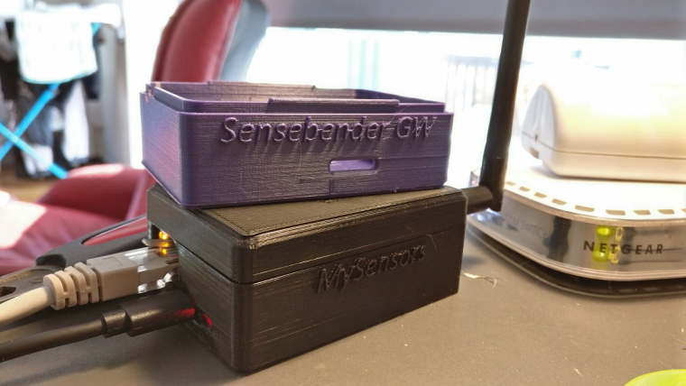
      Aaaand, it's up! Very good fit (the box).
      0_1491402196442_IMG_20170405_162045.jpg

      The box on top is just me trying out different colors of the case. 😉
      The one on top has better look. Different brands of PLA.

      posted in OpenHardware.io
      NiklasO
      NiklasO
    • RE: 💬 Debugging Sensors and the Gateway

      Is it possible to get the debug data over ethernet? It would be nice if you could remote debug your gateway.

      posted in Announcements
      NiklasO
      NiklasO
    • RE: Sun / cloud sensor?

      With the light sensor you should be able to identify cloudy days (I clearly see cloudy days in the history).
      Some scripting and you could use the lux-value, sunset and sunrise times to figure it out. Maybe adding a UV-meter to the mix. Hmmmm...

      Something like this one does:
      http://diffractionlimited.com/product/portable-cloud-sensor/
      "The sky temperature".

      https://mynasadata.larc.nasa.gov/science_projects/measuring-the-temperature-of-the-sky-and-clouds/

      Edit:
      We could use MLX90614 sensor to measure the sky temperature and compare to ground temperature and in that way, detect cloudy or sunny days.
      http://www.ebay.com/itm/MLX90614ESF-BAA-000-TU-ND-Infrared-Thermometer-Module-IR-Sensor-for-Arduino-/201402795181?hash=item2ee48ac4ad:g:Pl8AAOSw32lYorlr

      or

      http://www.ebay.com/itm/MLX90614ESF-BAA-000-TU-ND-Infrared-Thermometer-Module-IR-Sensor-for-Arduino-MO-/152234019326?hash=item2371dac9fe:g:fEYAAOSw9IpX0Qsl

      Info about using with Arduino:
      In this link we even have the correction factor and code that use the info from sensors:
      https://indiduino.wordpress.com/2013/02/02/meteostation/

      I will order a sensor and try this out! Should be able to port that to MySensors.

      posted in Hardware
      NiklasO
      NiklasO
    • RE: 💬 The Sensor Network

      In the example sketch for the RepeaterNode it has this info:

      • It is important that nodes that has enabled repeater mode calls
      • process() frequently. Repeaters should never sleep.

      So, is this for older sketches for versions below 2?
      Do we need to add something more to the example sketch?

      posted in Announcements
      NiklasO
      NiklasO
    • RE: 💬 Sensebender Gateway

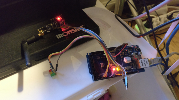
      Ordered from ITEAD. Nice to get rid of this stuff:
      0_1490290480771_IMG_20170323_180333.jpg
      Just nudging anything result in problems. 😉
      Time to fire up the 3D-printer.

      posted in OpenHardware.io
      NiklasO
      NiklasO
    • RE: 💬 Power Meter Pulse Sensor

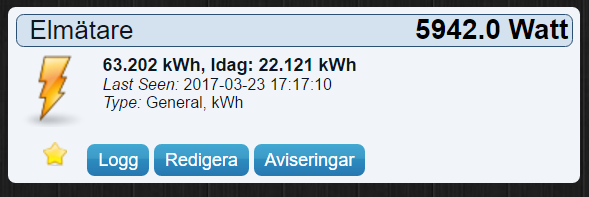
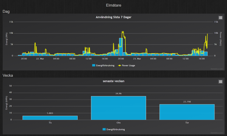
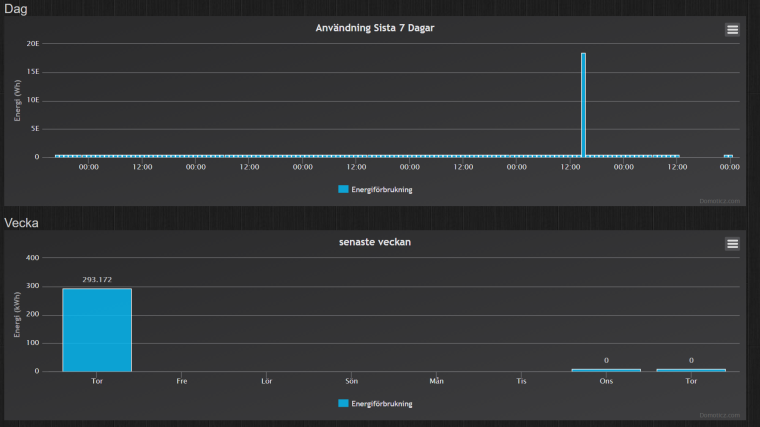
      Just changed from 1-wire counter to MySensors for logging my power consumption. Using the same LED detector as I did when using 1-wire. Also changed watt limit to 20 000 (my heat pump likes to use 9-10kW sometimes). The wires from the old 1-wire net now provide power for the new MySensors-sensor. I have 10 000 led blinks per kWh. Had som crazy counter values with 1-wire that totally messed up the graphs and haven't seen anything like that with this sketch. Let's hope it stays that way. 😉 Dumping data to Domoticz. This sensor gives me higher resolution as a bonus. The 1-wire counter was read every minute, this every 20-sec. 😉

      0_1490286464866_Domoticz_-_Google_Chrome_2017-03-23_17-27-32_78641890.png

      0_1490286540285_Domoticz_-_Google_Chrome_2017-03-23_17-28-46_94994234.png

      My old 1-wire counter with one crazy value messing upp all the graphs:
      0_1490286637201_Domoticz_-_Google_Chrome_2017-03-23_17-30-09_29365468.png
      I know that you can hold shift and click the value that is crazy to make the graphs show up good but you loose the data for the full day. That's not good. 😉

      posted in Announcements
      NiklasO
      NiklasO
    • RE: MYSBootloader 1.3pre2 testing

      @NiklasO
      Personally I set the node ID manually to avoid this
      #define MY_NODE_ID 30 // Sets a static id for a node
      And I group tens so all my 3X nodes are in kitchen, 4X in office, 11X in bedroom 1 and so on.

      Ah, yes. Setting static id sound like a solution to my problem. Thanks.

      posted in Development
      NiklasO
      NiklasO
    • RE: MYSBootloader 1.3pre2 testing

      I have changed the fuse settings for my setup. I don't know if it makes any difference but there is a fuse for "Preserve EEPROM memory through the Chip Erase cycle". Was noticing that my sensors was getting a new id every time I did some changes in my sketches and flashed using "Upload with programmer". I have not succeeded with OTA flashing yet.
      I also use the external crystal present on the Pro Mini. Using 0xFF, 0xD2 and 0xFE.
      Probably only used when programming using ICSP.

      MYSBL13.menu.cpu.8MHzatmega328=ATmega328 8MHz (XTAL, BOD1V8)
      MYSBL13.menu.cpu.8MHzatmega328.upload.maximum_size=30720
      MYSBL13.menu.cpu.8MHzatmega328.upload.maximum_data_size=2048
      MYSBL13.menu.cpu.8MHzatmega328.upload.speed=38400
      MYSBL13.menu.cpu.8MHzatmega328.bootloader.low_fuses=0xFF
      MYSBL13.menu.cpu.8MHzatmega328.bootloader.high_fuses=0xD2
      MYSBL13.menu.cpu.8MHzatmega328.bootloader.extended_fuses=0xFE
      MYSBL13.menu.cpu.8MHzatmega328.bootloader.file=MYSBootloader/MYSBL13pre_atmega328_8Mhz.hex
      MYSBL13.menu.cpu.8MHzatmega328.build.mcu=atmega328p
      MYSBL13.menu.cpu.8MHzatmega328.build.f_cpu=8000000L
      
      posted in Development
      NiklasO
      NiklasO
    • RE: 💬 Building a Raspberry Pi Gateway

      Thanks for adding signing.

      I want to use my rPi to generate random soft serials for my sensors.
      Could all three "gen" commands output the line to put in SecurityPersonalizer.ino like it does when using the "set" commands?

      posted in Announcements
      NiklasO
      NiklasO
    • RE: 💬 Sensebender Gateway

      Got this from one eBay seller when I asked why my order was delayed.
      "I am so sorry for the dalay. because of National Day in China, we were from 30th sep to 5th October on vacation."

      😉

      posted in OpenHardware.io
      NiklasO
      NiklasO
    • RE: LCD Clock and Text sensor node with new V_TEXT

      This is my test code. Not optimized, just testing. I have just started to play with arduino (got my first ever this month) so I can't say I know what I am doing. 😉 Made som changes in the code below, not tested yet. It compiles, guess that's good. 😉

      I have commented out stuff related to line1 because that is always showing the time and date, in code, from GW/controller. Enable if you want to control all 4 lines from Domoticz.

      Update display by using the domoticz api:
      json.htm?type=command&param=udevice&idx=XXXX&nvalue=0&svalue=Banana
      Replace XXXX with the IDX for each of the 3 lines. You'll see it when adding the 3 text devices in Domoticz. Then use the Event-system in Domoticz to add Lua-script to update the display as example in this thread.

      //Credits: https://forum.mysensors.org/topic/1957/lcd-clock-and-text-sensor-node-with-new-v_text
      
      //Soft signing.
      //#define MY_SIGNING_SOFT
      //#define MY_SIGNING_REQUEST_SIGNATURES
      //#define MY_SIGNING_SOFT_RANDOMSEED_PIN 7
      
      #define MY_RADIO_NRF24
      #define MY_REPEATER_FEATURE
      #define MY_DEBUG
      
      #include <TimeLib.h>
      #include <Wire.h>
      #include <LiquidCrystal_I2C.h>
      #include <SPI.h>
      #include <MySensors.h>
      
      //char lastLCD1[21] = "Line1"; //Line 1 always showing current time
      char lastLCD2[21] = "Line2";
      char lastLCD3[21] = "Line3";
      char lastLCD4[21] = "Line4";
      
      //20 whitespace characters used to clear your LCD line before printing to it.
      //Change to fit your LCD. Don't forget to change number of chars in the writeScreen function if needed.
      String LINE_BLANK = "                    ";
      
      boolean timeReceived = false ;
      unsigned long lastUpdate = 0, lastRequest = 0, lastDisplay = 0;
      
      //const byte LCD1_CHILD = 1;                          // Child ID for LCD line 1
      const byte LCD2_CHILD = 2;                          // Child ID for LCD line 2
      const byte LCD3_CHILD = 3;                          // Child ID for LCD line 3
      const byte LCD4_CHILD = 4;                          // Child ID for LCD line 4
      
      MyMessage textMsg(0, V_TEXT);
      
      // Initialize display. Google the correct settings for your display.
      // The follwoing setting should work for the recommended display in the MySensors "shop".
      LiquidCrystal_I2C lcd(0x27, 2, 1, 0, 4, 5, 6, 7, 3, POSITIVE);
      
      void before() {
        Wire.begin();                                       // I2C.
        lcd.begin(20, 4);                                   // LCD with 20 chars, 4 lines.
        lcd.setBacklight(HIGH);                             // Make sure backlight is on.
        writeScreen(0, "Waiting for GW...");                // Print initial text before contact with GW.                 
      }
      
      void setup(void)
      {
        Serial.begin(115200);                               // Start serial.
        requestTime();                                      // Request time from controller.
      }
      
      void presentation()  {
      
        sendSketchInfo("Domoticz LCD", "1.0");                    // Send the sketch version information to the gateway and Controller
      
        //present(LCD1_CHILD, S_INFO, "LCD_line1");
        //wait(500);
        present(LCD2_CHILD, S_INFO, "LCD_line2");
        wait(500);
        present(LCD3_CHILD, S_INFO, "LCD_line3");
        wait(500);
        present(LCD4_CHILD, S_INFO, "LCD_line4");
        wait(500);
        //send(textMsg.setSensor(LCD1_CHILD).set("-"));      // initialize the V_TEXT at controller for sensor to none (trick for Domoticz)
        send(textMsg.setSensor(LCD2_CHILD).set("-"));
        send(textMsg.setSensor(LCD3_CHILD).set("-"));
        send(textMsg.setSensor(LCD4_CHILD).set("-"));
      }
      
      void loop()     {
        // timer for loop delays
        unsigned long now = millis();
        // If no time has been received yet, request it every 10 second from controller
        // When time has been received, request update every hour
        if ((!timeReceived && (now - lastRequest > 10 * 1000)) ||
            (now - lastRequest > 3600000UL)) {              // request update from GW every hour to keep in sync
          // Request time from controller.
          Serial.println("Requesting time...");
          timeReceived = false;
          requestTime();
          lastRequest = now;
        }
      
        // Update sensors every 5 seconds
        if (now - lastDisplay > 5000) {
          lastDisplay = now;
          //request(LCD1_CHILD, V_TEXT, 0);                  // request new values from controller
          request(LCD2_CHILD, V_TEXT, 0);                  // request new values from controller
          request(LCD3_CHILD, V_TEXT, 0);                  // request new values from controller
          request(LCD4_CHILD, V_TEXT, 0);                  // request new values from controller
        }
      
        // Update LCD time every second
        if (now - lastUpdate > 1000) {
          LCD_time();
          lastUpdate = now;
        }
      }
      
      // This is called when a message is received
      void receive(const MyMessage &message) {
        if (message.type == V_TEXT) {                       // Text messages only
          Serial.print("Message: "); Serial.print(message.sensor); Serial.print(", Message: "); Serial.println(message.getString());     // Write some debug info
          //if (message.sensor == LCD1_CHILD) {
          //  writeScreen(0, message.data);
          //}
      
      // Don't forget to change "if" to "else if" when controlling all 4 lines:
          if (message.sensor == LCD2_CHILD) {
            writeScreen(1, message.data);
          }
          else if (message.sensor == LCD3_CHILD) {
            writeScreen(2, message.data);
          }
          else if (message.sensor == LCD4_CHILD) {
            writeScreen(3, message.data);
          }
        }
      }
      
      void receiveTime(unsigned long ts) {
        setTime(ts);
        timeReceived = true;
      }
      
      void LCD_time(void) {
        lcd.setCursor(0, 0);
        if (timeReceived) {
          lcd.print(year());
          lcd.print("-");
          printDigits(month());
          lcd.print("-");
          printDigits(day());
          lcd.print("     ");
          printDigits(hour());
          lcd.print(":");
          printDigits(minute());
        } else {
          writeScreen(0, "Waiting for time...");
        }
      }
      
      void printDigits(int digits) {
      //add leading 0 if digit = 0-9
        if (digits < 10)
          lcd.print('0');
        lcd.print(digits);
      }
      
      void writeScreen(int line, String text)
      {
        // Remove anything over 20 char in text.
        if (text.length() > 19)
        {
          text.remove(20);
        }
      
        // Clear the line
        lcd.setCursor(0, line);
        lcd.print(LINE_BLANK);
      
        // Set Line
        lcd.setCursor(0, line);
        lcd.print(text);
      }
      
      posted in My Project
      NiklasO
      NiklasO
    • RE: 💬 Easy/Newbie PCB for MySensors

      Just wanted to say that my first sensor on this board works great! Measuring passives in place. Worked first try.
      On battery, with booster and one DS18B20 temperature sensor.

      Great work @sundberg84!

      posted in OpenHardware.io
      NiklasO
      NiklasO
    • RE: 💬 Building a Raspberry Pi Gateway

      @raulandresmoch
      Sure. I use this with Domoticz on my Pi.
      "MySensors Gateway with LAN interface" as hardware pointing to 127.0.0.1:5003
      Also, I can connect with other controller software like MYSController from my other computers to my Pi-IP at port 5003.

      posted in Announcements
      NiklasO
      NiklasO
    • RE: 💬 Easy/Newbie PCB for MySensors

      My Dirty boards arrived today! Woho! Got 12 of them.

      0_1476279811632_20161012_153919-01-1.jpg

      posted in OpenHardware.io
      NiklasO
      NiklasO
    • RE: 💬 Building a Raspberry Pi Gateway

      @GertSanders said:

      @NiklasO

      Signing is not yet supported in the current Raspi Gateway.

      Ok, thanks.
      I now see that in this thread. Did not see the earlier discussion in the comments on the main page. Hope to see support soon.

      I have disabled signing for the time being but I want it on ofc. 😉

      posted in Announcements
      NiklasO
      NiklasO
    • RE: [security] Introducing signing support to MySensors

      Trying this:
      https://www.mysensors.org/build/raspberry

      How do I enable signing and give the gateway the serial, hmac and aes-key when running on Linux? (rPi).

      Edit: Pin 7 as random number generator maybe need some change?

      posted in Development
      NiklasO
      NiklasO
    • RE: 💬 Easy/Newbie PCB for MySensors

      @Nca78
      Ok, thanks.
      I'll try some more.

      posted in OpenHardware.io
      NiklasO
      NiklasO
    • RE: 💬 Building a Raspberry Pi Gateway

      Where do I put the security stuff for the signing?

      posted in Announcements
      NiklasO
      NiklasO
    • RE: MYSBootloader 1.3pre2 testing

      @tekka said:

      @NiklasO you can use the internal RC oscillator (that is 8Mhz), no need to use external XTAL. For AVR fuse calculator, refer to http://www.engbedded.com/fusecalc/ or http://eleccelerator.com/fusecalc/fusecalc.php?chip=atmega328p and the documentation therein.

      I don't understand the fusecalc yet. I don't know all the terms used on that calc page or how it really works but I'm learning I guess. 😉 The Pro Mini clones i got from eBay has this extremely small external 8 MHz (for 3.3V) and 16MHz (for 5V) crystal/oscillator/resonator or what they are called. Why is it there if not needed? Genuine interested here.

      posted in Development
      NiklasO
      NiklasO
    • RE: 💬 Easy/Newbie PCB for MySensors

      @sundberg84 said:

      @NiklasO - do you have any serial log?
      2,9V should be just fine for the radio, but it might freeze with spikes from booster or other power circuit. A 0,1cap from Out to Gnd on the booster might help.

      Try to remove the booster and verify if the radio works then - if so, its the booster. If not try another radio - we know the radios is very different quality sometimes.

      Thanks for the answers guys!

      Everything works as it should when all on battery.

      Out to GND already have a cap. The same one the radio use? If it sits between radio vcc and gnd-pin that would be the same as between Vout and GND on the booster, right? I have tried with caps at 0,1 - 100uF. The current one is at 47uF. The serial log say stuff about signing error and other like !TSM:UPL:FAIL when radio on battery and the rest on booster Vout. Reports radio OK at start. All has the same GND.
      The multi meter show a quite stable 3.3v output from the booster but I don't have any oscilloscope to see the eventual noise. I have tried different boosters but all are probably the same batch, marked "Canton-power" I think. Also, the radio seem to freeze the Gateway. My sensor tries to communicate with the gateway (I have green, yellow, and red leds connected to both gw and my testsensor). On the sensor the yellow and green blink momentarily and then it greets me with angry red led blinking at me. 😉 The gateway does the same ofc but often it freezes with all the three leds constantly on. To make the gateway accept connections again I have to reset it but this does only happen with this troublesome sensor with radio on bat, rest on booster. Other than that the gateway works great with my other sensors (all on battery only for now).

      posted in OpenHardware.io
      NiklasO
      NiklasO
    • RE: 💬 Easy/Newbie PCB for MySensors

      @sundberg84 said:

      AMS1117

      mmmm I would like to see a board with room for AMS1117 and caps... 🙂

      While waiting for my Newbie PCBs to arrive I have built my own test sensor on a bit of breadboard. Got the new 0,8-3.3v to 3.3v today. My boosters. So, I just cut the trace going from the battery to the rest of the components and arduino and there I connected my booster. VIN directly from bat + and gnd from bat -, Also, everything else that need GND is connected to the same place. I then reconnected the plus power rail to the power coming from the booster. I also moved the radio connection so that if feed directly from the battery. Measurements show me 3.3 v to arduino and other sensors and about 2.9 to the radio directly from batt. Something does not want to work. It is something with the power to the radio. Running sensor on battery only, no booster, works just fine. Running node with everything on vout from the booster, it just won't work. The radio struggles to do something useful but it fails. Running radio on batt and the rest on booster does not work. 'But, if I power the node with power from the serial adapter. the node woks again but only if the battery provide power to the radio at the same time.

      Any suggestions? Quite tired, can be messy 😉

      posted in OpenHardware.io
      NiklasO
      NiklasO
    • RE: LCD Clock and Text sensor node with new V_TEXT

      @Qu3Uk said:

      @NiklasO I have something similar running on MYS 2.0 and can paste the code. I'm using a 4x1 display and using V_VAR-1-4 to send each line over.
      If that's useful to you I can post it.

      Yes please. I ported to 2.0 late yesterday and it works ok. I have 4 lines, 20 chars.

      posted in My Project
      NiklasO
      NiklasO
    • RE: MYSBootloader 1.3pre2 testing

      Flashed one of my boards with new bootloader. Signing fails. Uploaded and ran the personalisation again and then the original sketch, still "signature verification failed".

      Edit, Went back to standard bootloader, cant get signing to work again. Hm. Doing something wrong maybe.

      Edit 2, got it working again. Flashing bootloaders, clearing eeprom, personalisation, doing it many times and at last it started to work again with (soft) signing enabled. Have not been able to upgrade my sketch using OTA yet..

      How would I configure the boards.txt for my boards with 3.3v, 8MHz and 8MHz external crystal? I'm really new to all this. Never worked with arduinos before and I don't fully understans the fuse calculator yet. 😉

      posted in Development
      NiklasO
      NiklasO
    • RE: LCD Clock and Text sensor node with new V_TEXT

      Does this work with MySensors 2.0? If someone has this running on 2.0, please share the code. 🙂

      posted in My Project
      NiklasO
      NiklasO
    • RE: Setting parameters in nodes

      @hek
      Ok, thanks. Just started using MySensors, learning as I go. 😉

      posted in Feature Requests
      NiklasO
      NiklasO
    • RE: Setting parameters in nodes

      This.
      It would be great if able to set wake-up periods and other parameters in the controller software and save it to the node when it wakes up. Like z-wave does. You can change parameters and save them. The node wakes up, sends the data as it should and looks if there is any config updates from the controller. If there is, it saves them and goes back to sleep. 🙂

      posted in Feature Requests
      NiklasO
      NiklasO
    • RE: Easy/Newbie PCB for MySensors

      @sundberg84 said:

      @NiklasO - Thanks! I hope it will suite you well!
      The wait is a pain, but well worth it in the end. Sounds like got alof going already!

      Hehe, we can create a forum group - "sundberg dreamteam!" 😉

      hehe yeah, just need to change my last name back to my original one but I don't know if my kids likes that idea. 😉

      Where do you get your x to 3.3v boost converter? Found some on eBay but they are quite expensive if comparing to x to 5v versions.

      posted in Hardware
      NiklasO
      NiklasO
    • RE: Easy/Newbie PCB for MySensors

      This board looks great! Definitely going to order some.

      Just getting started with MySensors. Waiting for over 20 orders from eBay with stuff. Should be fun!
      Already running Domoticz (Pi 2) with RFXtrx433, 1-wire and z-wave. Going to build a serial gateway for direct connection to the Pi.

      My last name before I married (now divorced) was Sundberg btw. Could have had Sundberg82 as nickname. 😉

      posted in Hardware
      NiklasO
      NiklasO