The Perl-Script i'm using instead of a controller, because obviously no controller supports this yet.
#!/usr/bin/perl
use Device::SerialPort;
use POSIX qw(strftime);
use Data::Dumper;
use Time::HiRes qw (sleep);
use Time::HiRes qw(time);
my $port = Device::SerialPort->new("/dev/ttyUSB1");
$| = 1;
use Time::HiRes qw(time);

$port->baudrate(115200);
$port->databits(8);
$port->parity("none");
$port->stopbits(1);

my $buffer;
my %transfers;

print "Waiting for incoming transfers...\n";

while (1) {
	my ($count,$saw)=$port->read(256);
	if($count > 0 || length($buffer) > 0)
	{
		$buffer .= $saw;
		my ($cmd, $rest) = split(/\n/, $buffer, 2);
		if(defined($rest))
		{
			if(@m = $cmd =~ /([0-9]*);([0-9]*);([0-9]*);([0-9]*);([0-9]*);(.*)/g)
			{
				my ($node_id, $child_sensor_id, $message_type, $ack, $sub_type, $payload) = @m;
		#		print "node_id: $node_id, child_sensor_id: $child_sensor_id, message_type: $child_sensor_id, ack: $ack, sub_type: $sub_type, payload: $payload \n";
				if($sub_type eq "25")
				{
					if($payload eq "START" && $transfers{$node_id}{'state'} == 0)
					{
						print "New transfer incoming from node $node_id.\n";
						$transfers{$node_id}{'start_time'} = time();
						$transfers{$node_id}{'state'} = 1;
						$transfers{$node_id}{'count'} = 0;
						my $time = strftime("%Y-%m-%d-%H-%M-%S", localtime);
						open ($transfers{$node_id}{'FH'}, ">>node-".$node_id."-".$time.".jpg");
						binmode($transfers{$node_id}{'FH'});
					}

					if($payload eq "END" && $transfers{$node_id}{'state'} == 1)
					{
						close($transfers{$node_id}{'FH'});
						$transfers{$node_id}{'state'} = 0;
						my $duration = time() - $transfers{$node_id}{'start_time'};
						my $bps = $transfers{$node_id}{'count'} * 24 / $duration;
						my $pps = $transfers{$node_id}{'count'} / $duration;
						print "Transfer from $node_id finished.\n";
						print "$duration seconds, $bps Bytes/s, $pps Packets/s\n";
					}
				}
				elsif($sub_type eq "24")
				{
					if($transfers{$node_id}{'state'} == 1)
					{
						$transfers{$node_id}{'count'}++;
						print { $transfers{$node_id}{'FH'} } pack('H*',$payload);
					}
				}
			}
			$buffer = $rest;
		}
	}
        #Check for timeout
        while(($node_id) = each %transfers)
        {
	        my $duration = time() - $transfers{$node_id}{'start_time'};
               	if($duration > 120 && $transfers{$node_id}{'state'} == 1)
                {
                	close($transfers{$node_id}{'FH'});
                        $transfers{$node_id}{'state'} = 0;
                        print "Warning: Timeout from node $node_id. Transfer cancelled.\n";
                }
	}
	sleep (0.001);
}
The sketch:
#include <MySensor.h>
#include <SPI.h>
#include <Adafruit_VC0706.h>
#include <SoftwareSerial.h>

#undef DEBUG

SoftwareSerial cameraConnection = SoftwareSerial(6,7);

Adafruit_VC0706 cam = Adafruit_VC0706(&cameraConnection);

#define CHILD_ID 3

MySensor gw;
MyMessage msg(CHILD_ID,V_VAR1);
MyMessage msg2(CHILD_ID,V_VAR2);

void setup()
{
  gw.begin();

  gw.present(CHILD_ID, S_CUSTOM);

  if (cam.begin()){}
  else { return; } //Abort the transfer if camera does not initialize

  cam.setImageSize(VC0706_640x480);
  delay(3000);
  snapAndSend();
  cam.reset();
}

//Do nothing.
void loop()
{

}

void snapAndSend()
{
  cam.takePicture();
  uint16_t jpgLen = cam.frameLength();
  Serial.print("Sending Picture of ");
  Serial.print(jpgLen, DEC);
  Serial.println(" Bytes.");
  gw.send(msg2.set("START"));
  while (jpgLen > 0)
  {                     //Send off 24 bytes of data at a time
    uint8_t *buffer;
    uint8_t bytesToRead = min(24, jpgLen);
    buffer = cam.readPicture(bytesToRead);
    gw.send(msg.set(buffer, bytesToRead));
    jpgLen -= bytesToRead;
  }
  Serial.println("Done.");
  gw.send(msg2.set("END"));
}
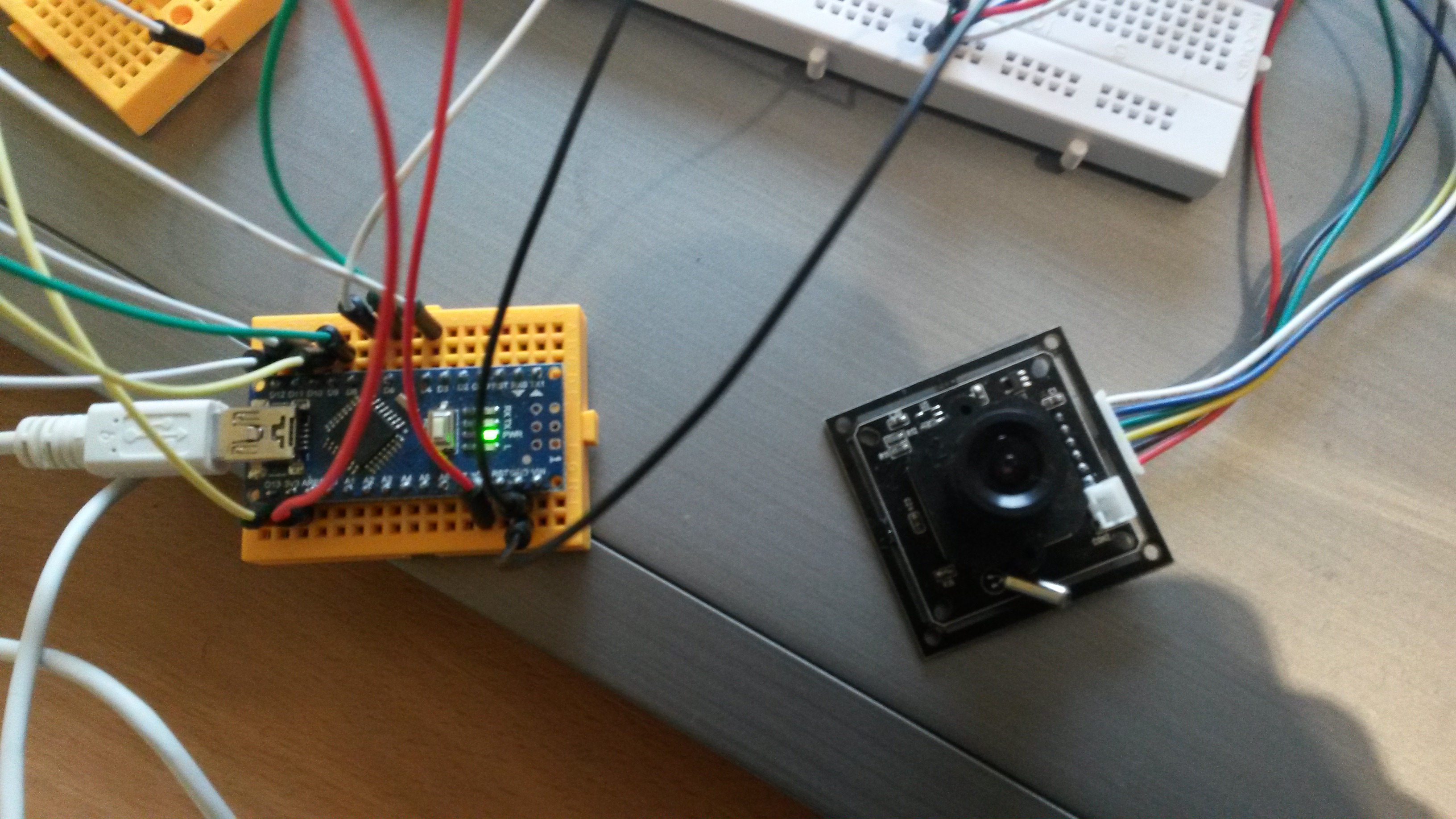
Hardware:
Typical MySensors-Node and a Serial TTL Camera like this:
http://aliexpress.com/item/NEW-RS232-TTL-JPEG-Digital-Serial-Port-CCTV-Camera-Module-SCB-1-with-video-out-Support/1975852463.html