@mfalkvidd
Better start from the beginning.
What I need to change in the code or configurations (MyConfig.h) to work the physical switch when the failure of the gateway.
Thank You
okos
Posts
-
MY_TRANSPORT_DONT_CARE_MODE -
MY_TRANSPORT_DONT_CARE_MODE@mfalkvidd
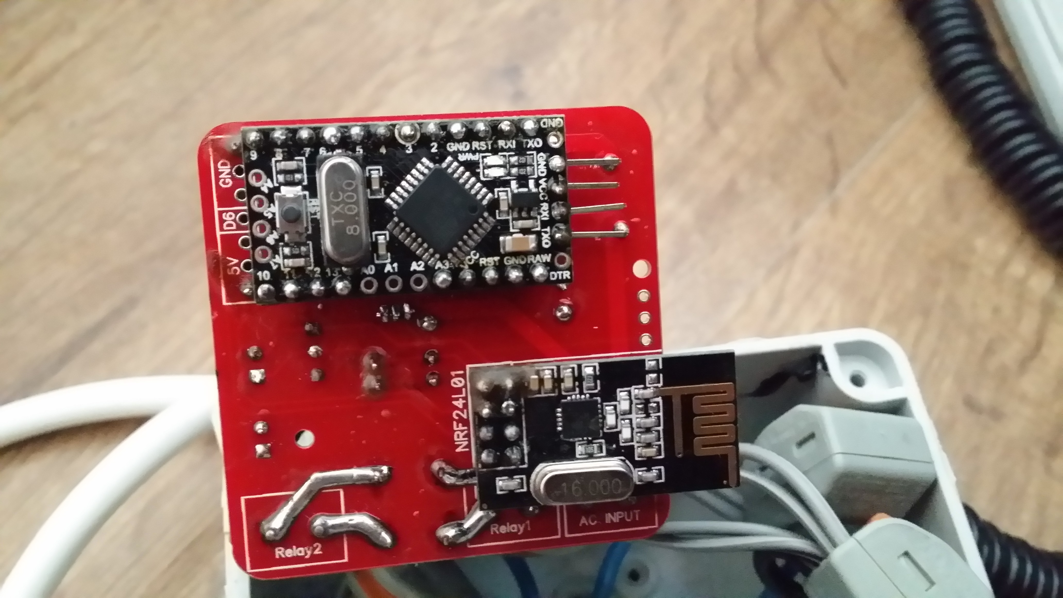
I would like to control physical switch even if the gateway is unavailable (use domoticz and this project https://www.openhardware.io/view/77/AC-DC-double-solid-state-relay-module).Now physical switch works only when is communicating with the gateway.
Thank You
// Example sketch för a "light switch" where you can control light or something // else from both vera and a local physical button (connected between digital // pin 3 and GND). // This node also works as a repeader for other nodes #define MY_RADIO_NRF24 #include <MySensors.h> #include <SPI.h> #include <Bounce2.h> #include <OneWire.h> #include <DallasTemperature.h> #define RELAY_PIN 3 // Arduino Digital I/O pin number for relay #define RELAY_PIN_2 5 #define BUTTON_PIN 4 // Arduino Digital I/O pin number for button #define BUTTON_PIN_2 7 #define ONE_WIRE_BUS 8 #define CHILD_DSB_ID 13 #define CHILD_ID_2 12 #define CHILD_ID 11 // Id of the sensor child #define RELAY_ON 1 #define RELAY_OFF 0 Bounce debouncer = Bounce(); int oldValue = 0; bool state; Bounce debouncer2 = Bounce(); int oldValue2 = 0; bool state2; MyMessage msg(CHILD_ID, V_LIGHT); MyMessage msg2(CHILD_ID_2, V_LIGHT); MyMessage msgTemp(CHILD_DSB_ID, V_TEMP); OneWire oneWire(ONE_WIRE_BUS); DallasTemperature sensors(&oneWire); // Pass the oneWire reference to Dallas Temperature. void presentation() { // Send the sketch version information to the gateway and Controller sendSketchInfo("Double Relay & Button", "0.2"); // Register all sensors to gw (they will be created as child devices) present(CHILD_ID, S_LIGHT); present(CHILD_ID_2, S_LIGHT); present(CHILD_DSB_ID, S_TEMP); } void setup() { sensors.begin(); sensors.setWaitForConversion(false); // Setup the button pinMode(BUTTON_PIN, INPUT); // Activate internal pull-up digitalWrite(BUTTON_PIN, HIGH); // Setup the button pinMode(BUTTON_PIN_2, INPUT); // Activate internal pull-up digitalWrite(BUTTON_PIN_2, HIGH); // After setting up the button, setup debouncer debouncer.attach(BUTTON_PIN); debouncer.interval(5); debouncer2.attach(BUTTON_PIN_2); debouncer2.interval(5); // Make sure relays are off when starting up digitalWrite(RELAY_PIN, RELAY_OFF); // Then set relay pins in output mode pinMode(RELAY_PIN, OUTPUT); digitalWrite(RELAY_PIN_2, RELAY_OFF); // Then set relay pins in output mode pinMode(RELAY_PIN_2, OUTPUT); // Set relay to last known state (using eeprom storage) state = loadState(CHILD_ID); digitalWrite(RELAY_PIN, state ? RELAY_ON : RELAY_OFF); state2 = loadState(CHILD_ID_2); digitalWrite(RELAY_PIN_2, state2 ? RELAY_ON : RELAY_OFF); } /* * Example on how to asynchronously check for new messages from gw */ void loop() { static float prevTemp = 0; debouncer.update(); debouncer2.update(); // Get the update value int value = debouncer.read(); int value2 = debouncer2.read(); if (value != oldValue) { send(msg.set(state ? false : true), true); // Send new state and request ack back } oldValue = value; if (value2 != oldValue2) { send(msg2.set(state2 ? false : true), true); // Send new state and request ack back } oldValue2 = value2; // Fetch temperatures from Dallas sensors sensors.requestTemperatures(); // Fetch and round temperature to one decimal float temperature = static_cast<float>(static_cast<int>(sensors.getTempCByIndex(0) * 10.f)) / 10.f; if (temperature != -127.00f && temperature != 85.00f && prevTemp != temperature) { // Send in the new temperature send(msgTemp.set(temperature, 1)); Serial.print("Sent temperature: "); Serial.println(temperature); prevTemp = temperature; } } void receive(const MyMessage &message) { // We only expect one type of message from controller. But we better check anyway. if (message.isAck()) { Serial.println("This is an ack from gateway"); } if (message.type == V_LIGHT && message.sensor == 11) { // Change relay state state = message.getBool(); digitalWrite(RELAY_PIN, state ? RELAY_ON : RELAY_OFF); // Store state in eeprom saveState(CHILD_ID, state); } else if (message.type == V_LIGHT && message.sensor == 12) { state2 = message.getBool(); digitalWrite(RELAY_PIN_2, state2 ? RELAY_ON : RELAY_OFF); // Store state in eeprom saveState(CHILD_ID_2, state2); // Write some debug info Serial.print("Incoming change for sensor:"); Serial.print(message.sensor); Serial.print(", New status: "); Serial.println(message.getBool()); } } -
MY_TRANSPORT_DONT_CARE_MODEStill is problem with physical button when gateway is not responsible.( i can not off and on the lights )
For example, when a server domoticz failure. -
MY_TRANSPORT_DONT_CARE_MODEHello, two month ago i asked question
In this topic: https://forum.mysensors.org/topic/3671/ac-dc-double-solid-state-relay-module/93
"Hello.
I would like to ask whether it is normal that the switch does not work if the server domoticz off? I want to use the switch only crash server :flushed: now i cant"And i got a reply from @hek it will be in the new library.(post 90)
Now i see 2.1.0 , and i have question now it is work?Thank You
-
💬 AC-DC double solid state relay module@tonnerre33
Avesome photogallery :smile:
whose sketch you used? because I have a problem with phisycal switches if I use sketch of Nca78 (I wrote about this earlier) -
💬 AC-DC double solid state relay module@ludoarchi ![alt text]

-
💬 AC-DC double solid state relay moduleHello.
I tried to upload my two boards ( arduino pro mini 8Mhz , 3,3 V ) modified sketches but returned to sketch Nca78 (with DS18B20), unfortunately, does not operate a physical switch. Sometimes phisical switch changes state in domoticz ( not every time ) but relays do not change state.
Switching on and switching off the lights of domoticz changes state relay without a problem.
What could be wrong ? -
💬 AC-DC double solid state relay moduleIt possible implement this option in mysensors 2.0 ?
-
💬 AC-DC double solid state relay module@hek said:
You can disable this behaviour by defining:
#define MY_TRANSPORT_DONT_CARE_MODE
#define MY_PARENT_NODE_ID 0
sorry for the ridiculous question but I have to enter into a sketch? or MyConfig.h?
-
💬 AC-DC double solid state relay moduleThanx for the answers
This is not good news from the switch does not work without a server. Mr.const, Do you use esp8266 in domoticz to control the light?edit: hek, I not noticed your post.
What changes adding this?#define MY_TRANSPORT_DONT_CARE_MODE #define MY_PARENT_NODE_ID 0``` -
💬 AC-DC double solid state relay moduleHello.
I would like to ask whether it is normal that the switch does not work if the server domoticz off? I want to use the switch only crash server :flushed: now i cant -
💬 AC-DC double solid state relay module@Nca78 said:
Running fine now, nearly one week with a load connected (2*28W tubes) and switching on/off without a problem.
Super :smile:
I solder already the third board, and I hope that the thermometer will be visible in domoticz. -
Repeater Node, problems@flopp said:
I will give up soon
Today it start do NOT send again. It is raining if that can make problem. I reprogram Repeater with DEBUG ON and could see that the repeater didn't have connection to GW.
I changed RF on Serial GW, didn't help.
I change to have external power for RF on GW, didn't help.I changed RF on Repeater, didn't help.
I change to have external power for RF on Repeater, didn't help.
Reprogram Repeater, didn't help.Finally I restarted my RPi, that helped.
I have 6-8 meters from GW to Repeater, there is 2 inner walls, 1 brick wall, 1 wood wall and the GW is inside my drawer so some woods there as well.
It is a Serial GW with nRF24L01+ PA + LNA with shield. I take 5 volt from UNO to an adapter that step-down to 3.3V I have Cap on GW
Repeater is Arduino Nano with nRF24L01+ PA + LNA no shield and Cap, power from 5v Nano to an adapter step-down to 3,3VWhat is next step?:flushed:
Reposition and put it to the test in the vicinity of the goal.
Exclude in this way the problem of the range.
It's just a tip :smiley: -
💬 AC-DC double solid state relay module@Nca78
You check out what's happened? My plate at the moment is working without a problem and the temperature in the box 35°C (bulb 40W)But on the new board my domoticz does detect ds18b20 and I think the problem may be inaccurate soldering DS18B20 because it is a very small gap between the legs.
What do you think? -
💬 AC-DC double solid state relay moduleThanks Nca78, I'm waiting for a revised code
-
💬 AC-DC double solid state relay module@okos did you fix your problem ? I see your deleted message.
Now everything is ok.
Nrf changed, and changed the position of the gate (it is now above - on the fridge :))But I have another problem
I used the code from Konstantin Kolesnichenko (thanks), and even after the power is changing relay.Example:
on relay 1
off Relay 2turn off the power, and after power returning I
on relay 2
off Relay 1Why exchange ?
-
Repeater Node, problems@flopp said:
RPi with Domoticz, MySensors 1.5.1
I had an Ethernet GW(UNO) and a Repeater Node(NANO clone) working OK but sometimes the nodes couldn't send data, maybe 4 times per day, I could live with that but of course 100% data is much nicer :) my nodes sends data every 30/60 min.
I changed to a Serial GW because my router sometimes stopped working so I had no connection to Ethernet GW.
Since that time I lost lots of data, I have always though the problem was the Serial GW until yesterday. I checked my Logfile that write every time a node is not sending data for more than 70 minutes, it was always the nodes that was sending data through the Repeater Node, since the nodes are far away from Serial GW.Yesterday I changed to have NO DEBUG and from baud rate from 57600 to 9600 and since then I have data all the time.
Can it be that critical to NOT have DEBUG?
Could it be the baud rate that made my problems before?
Maybe the sketch was not 100% complete and after I upload the new sketch it was 100% correct?Hi floop, where You changed baud rate?
this line in MyConfig ?
I ask, because sometimes I have a problem with communication and my node are promini 3.3V 8MHz// Serial output baud rate (for debug prints and serial gateway) #define BAUD_RATE 115200``` -
💬 AC-DC double solid state relay module@Nca78 said:
@okos if you have the device in Domoticz it means it could run, and send data to the gateway controller.
Did you change anything in hardware of software between the moment you added the node/sensor to Domoticz and the moment you tried to activate it ?
Are you sure your settings for the ACK are ok ? Maybe you are not sending one in the node but waiting from one in Domoticz ? Check the "Ack" column in Domoticz and if it's true try to change it to false.Thanks for the answer :smiley: Nca78, but I do not know where to look for settings Ack.
Please help -
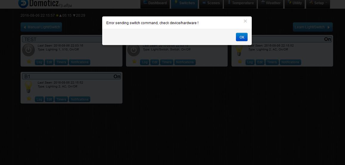
💬 AC-DC double solid state relay moduleHi I did everything according to the project and I have problem "error sending the switch command check device / hardware"
One change for me is 10nF capacitor instead of 100nF (I dont have now
)
Could this be the reasons this error?!

