Navigation

    • Register
    • Login
    • OpenHardware.io
    • Categories
    • Recent
    • Tags
    • Popular
    1. Home
    2. OliverDog
    3. Posts
    • Profile
    • Following
    • Followers
    • Topics
    • Posts
    • Best
    • Groups

    Posts made by OliverDog

    • RE: Mi-Light controller for Mysensors

      Hi.
      is this thread still alive?

      Can I use this to solve my problem?
      This is the problem:

      • I want to control my pool lights (controlled by RGB-FUT037 from milight - 2.4ghz) using the original Mi-Light Wall Panel Controller T3 - which sends 2.4ghz... but both are in different floors. Fut037 is inside que pool's machine house and the Wall Panel is on Gourmet's Balcony.

      What I need:

      • An arduino node receives the code from Wall Panel using maybe a NRF24L01 module, then send to another arduino node through wifi (NodeMCU / ESP8266), which finally, reproduces the code using another NRF24L01, reaching the FUT037.
      posted in My Project
      OliverDog
      OliverDog
    • RE: Water Leak Detection

      Yes, I understand how to make a reed talk to my Home Automation, but I don't see any wires outcomming from those Class D @zboblamont posted above.

      My Newbie question was about those Class D beeing a reed sensor, or electronic switch, that sends a open/close signal or if I would need a DIY way to read a ordinary water flow meter...

      But after check Datasheet from V200H I could notice a small plug on top and the wired pulse info... so It would act like a reed sensor with a pulse for each liter spent!
      Now I got it.

      But How much does it cost???
      And won't be better an external sensor, just like that I posted, called Flume Water Monitor, once Class D could lower pressure from system?

      posted in Hardware
      OliverDog
      OliverDog
    • RE: Water Leak Detection

      Sorry about newbie question, but how could I read water flow on Home Assistant using those Class D? Do they send measurement wirelessly or do I need to build some reading sensor outside?

      By the way, have you seen Flume Water Monitor? For $ 199,00

      https://www.flumetech.com/

      It has already been integrated with HASS
      https://www.home-assistant.io/integrations/flume/

      posted in Hardware
      OliverDog
      OliverDog
    • RE: Water Leak Detection

      @NeverDie

      @chrismyers81 and @TD22057, from arduino forum, found a way to use it. Check here:
      https://forum.arduino.cc/index.php?topic=256231.msg2494469#msg2494469

      But this rope will certainly disagree with my wife's idea of ​​beautiful decor! 😅

      Despite all the work on finding the best place to place the sensor, accidents can occur, of course, but have those people worked on finding that place properly?

      I think the best way avoiding those disasters is reading the main water flow and create automations based on volume of water, linked with others events, just like garden irrigation, people in the bathrooms, pool filling, car wash, time of day and, of course, flood sensors at strategic points. This is the way I will do!

      The problem is how to measur water flow without adding chinese components in contact with your water!

      posted in Hardware
      OliverDog
      OliverDog
    • RE: Water Leak Detection

      @TD22057

      Great work, and thanks for the quick answer!
      I will try using it...

      I noticed you have coded a sonar sensor library as well.
      I have another projeto for auto flushing an urinal, and got this sensor:
      https://www.aliexpress.com/item/32332773388.html?spm=a2g0s.9042311.0.0.3b60b90avbfLZ9

      Could it work with your library?

      Thanks again!!!

      posted in Hardware
      OliverDog
      OliverDog
    • RE: Water Leak Detection

      Great job @TD22057

      Could you share your sketch???

      I´m working in something similar, but without the water sensor.
      The valve is similar as well, buy it has 3 way, but still with 5 wires.

      Do you remender, or could check, how did you configured the valve sensor? Debouncering or not?

      I want select water from two different places, so the 3 way...

      My project has a button to local valve operation, two leds to indicate from where water is comming, H-bridge to control the valve motor, and I use Home Assistant receiving and controlling valve status, and receiving the signal from valve´s status sensor.

      Here is my code:

      #define MY_DEBUG
      #define MY_RADIO_NRF24
      #define MY_REPEATER_FEATURE
      #define MY_NODE_ID 10
      
      #include <SPI.h>
      #include <MySensors.h>
      #include <DHT.h>  
      // #include <Bounce2.h>
      
      // PINAGEM
      #define int1 6   // ATUADOR PRA H BRIDGE
      #define int2 7   // ATUADOR PRA H BRIDGE
      #define button 4    // BOTAO LOCAL PARA MUDANÇA
      #define info_rua 11   // SENSOR RETORNO DA VALVULA QUANDO RUA SELECIONADO
      #define info_cist 12  // SENSOR RETORNO DA VALVULA QUANDO CISTERNA SELECIONADO
      #define led_rua 9    // LED ACENDE PRA ÁGUA DA RUA
      #define led_cist 10   // LED ACENDE PRA ÁGUA DA CISTERNA
      
      #define CHILD_ID_ACT 0   
      #define CHILD_ID_ESTADO 1     
      
      // MOTOR
      boolean buttonState = LOW;
      int rotDirection = 0;     // 0 PRA CISTERNA E 1 PRA RUA
      int pressed = false;
      bool initialValueSent = false;
      bool state;
      
      //sensores de fim de curso
      int valor_rua = 0; 
      int valor_cist = 0; 
      
      MyMessage msgSwitch(CHILD_ID_ACT, V_STATUS);   // SWITCH PARA MUDAR O ESTADO
      MyMessage msgState(CHILD_ID_ESTADO, V_TRIPPED);  //SENSOR DO ESTADO
      
      void presentation()  
      { 
        sendSketchInfo("Seletor Agua", "1.0");
        wait(200);
        present(CHILD_ID_ACT, S_SPRINKLER);
        wait(200);
        present(CHILD_ID_ESTADO, S_SPRINKLER);
      }
      
      void setup()  { 
        pinMode(int1, INPUT);
        pinMode(int2, INPUT);
        pinMode(button, INPUT);
        pinMode(info_rua, INPUT);
        pinMode(info_cist, INPUT);
        pinMode(led_rua, OUTPUT);
        pinMode(led_cist, OUTPUT);
      
        //definir estado inicial da valvula
        digitalWrite(int1, LOW);
        digitalWrite(int2, HIGH);
        digitalWrite(led_rua, LOW);
        digitalWrite(led_cist, HIGH);
        send(msgSwitch.set(0));
        
        // setup do botao e dos sensores de fim de curso
        digitalWrite(button, HIGH);
        digitalWrite(info_rua, HIGH);
        digitalWrite(info_cist, HIGH);
      }
      
      
      void loop()  { 
        valor_rua = digitalRead(info_rua);
        valor_cist = digitalRead(info_cist);
        
        // valores iniciais
        if (!initialValueSent) {
          Serial.println("Sending initial value");
          send(msgSwitch.set(0));
          send(msgState.set(0));
          Serial.println("Requesting initial value from controller");
          request(CHILD_ID_ACT, V_STATUS);
          wait(2000, C_SET, V_STATUS);
        }
        
        // ler estado do botão
        if (digitalRead(button) == true) {
          pressed = !pressed;
        }
        while (digitalRead(button) == true);
        wait(20);
        
        // se botao pressionado
        if (pressed == true & rotDirection == 0) {
          digitalWrite(int1, HIGH);
          digitalWrite(int2, LOW);
          digitalWrite(led_cist, LOW);
          rotDirection = 1;
          send(msgSwitch.set(1));
          wait(20);
        }
        if (pressed == true & rotDirection == 1) {
          digitalWrite(int1, LOW);
          digitalWrite(int2, HIGH);
          digitalWrite(led_rua, LOW);
          digitalWrite(led_cist, HIGH);
          rotDirection = 0;
          send(msgSwitch.set(0));
          wait(20);
        }
        
        if (valor_rua == 1) {
          digitalWrite(led_rua, HIGH);
        }
        if (valor_rua == 0) {
          digitalWrite(led_rua, LOW);
        }
        if (valor_cist == 1) {
          digitalWrite(led_cist, HIGH);
        }
        if (valor_cist == 0) {
          digitalWrite(led_cist, LOW);
        }
        
      }
      
      void receive(const MyMessage &message) {
        if (message.isAck()) {
           Serial.println("This is an ack from gateway");
        }
      
        if (message.type == V_STATUS) {
          if (!initialValueSent) {
            Serial.println("Receiving initial value from controller");
            initialValueSent = true;
          }
          state = message.getBool();
          if (state == 0) { 
            digitalWrite(int1, LOW);
            digitalWrite(int2, HIGH);
            digitalWrite(led_rua, LOW);
            digitalWrite(led_cist, HIGH);
            rotDirection = 0;
            send(msgSwitch.set(0));
          }
          if (state == 1) { 
            digitalWrite(int1, HIGH); 
            digitalWrite(int2, LOW);
            digitalWrite(led_rua, HIGH);
            digitalWrite(led_cist, LOW);
            rotDirection = 1;
            send(msgSwitch.set(1));
          }
        }
      }
      
      posted in Hardware
      OliverDog
      OliverDog
    • RE: How to cheat thermostats?

      Hi!
      After 1 year, Did this post result in any sketch?

      I want to use a similar valve @executivul suggested, with 5 wires as well!

      Did you get success using mysensors @KimmoHop ?

      Tks

      posted in General Discussion
      OliverDog
      OliverDog
    • RE: Video How To: Battery Powered Chair Occupancy (Contact) Sensor

      I had just cleaned it!!! My wife gave up caring about this desk...😏

      I found my multimeter fuse was burned... so I wired its base poles and now I can measure:

      Sleeping + Reed Disconnected - most time 6 uA
      Sleeping + Reed Connected - most time 9 uA
      When sending new status to gateway - 25 - 230 uA (around 140 uA most times)
      Sending time was less than 1 second.

      2 AA will give me 29 years (battery certainly will die first)
      2 AAA - 12 years.
      1 CR2032 - 2,5 years.

      Thanks for the help...

      posted in My Project
      OliverDog
      OliverDog
    • RE: Video How To: Battery Powered Chair Occupancy (Contact) Sensor

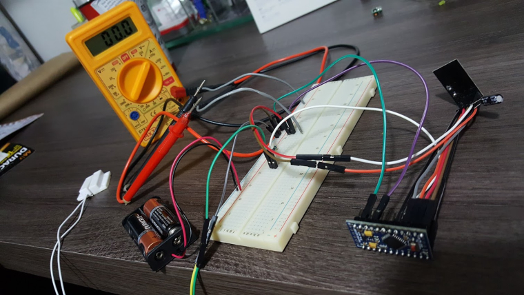
      Great!!! Got it working, but can't measure the consumption...
      My multimeter shows always 000.
      The sensors is working fine and reporting properly while connected to multimeter, but always 0 current...
      Tried 200u, 2000u, 20m and 200m, always reporting zero... Is is that low?

      Did I connect something wrong??? (multimeter in series with positive battery pole and circuit line in (Radio+APM+1M ResistorPin3)
      Or is my aliexpress multimeter that bad???

      0_1502410544175_20170810_210709.jpg

      posted in My Project
      OliverDog
      OliverDog
    • RE: Video How To: Battery Powered Chair Occupancy (Contact) Sensor

      Thanks for sharing this awesome project...

      I want to install all my windows with reed sensors powered by 2AA alcaline batteries and would like they last more than 5 years... and I think your project fits perfectly
      How long do those used batteries last?

      Did you implement what @Nca78 suggested?

      I have already cut LED and Power Regulator from Arduino Pro Mini 3.3v and will change bootloader.
      Have you choosen the best (lowest power consumption) bootloader to use?

      I would try the MYSBootloader_1MHz.hex from MySensors GitHub.
      Would the optiboot_atmega328_01M_009600_NOLED from GertSanders better for low power?

      Thanks for the help...

      posted in My Project
      OliverDog
      OliverDog
    • RE: RGB LED strip

      @maghac I have posted the issue (not working VAR1 and VAR2 on Home Assistant) on the HA forum, and got steps for asking the implement...
      I will ask for such implement and it may work later...
      Thanks for the help...

      By the way, I did not test the switches but seems doing the job...

      posted in My Project
      OliverDog
      OliverDog
    • RE: RGB LED strip

      the new sketch is even better... it responds faster than the other...

      but I still don't have fading effects... just the one that you have configured on the sketch (20) which is awesome by the way...

      It seems that Home Assistant does not send neither V_VAR1 nor V_VAR2 messages...

      the command:
      {"entity_id":"light.rgb_leds_12_1", "color_name":"green", "brightness_pct": 15, "transition":20}

      shows the same effect that the command:
      {"entity_id":"light.rgb_leds_12_1", "color_name":"green", "brightness_pct": 15, "transition":1}

      I will try HASS forum!
      Thank you very much.

      posted in My Project
      OliverDog
      OliverDog
    • RE: RGB LED strip

      @maghac , great work!!!

      I want to build a battery powered Mood Light based on your sketch and RGB Common Cathode Leds (4 or 5 of them).

      Before getting those RGB leds yet (already ordered but it takes 2 months to receive) I tested your sketch with three ordinary 3 mm colored leds - Green, Red and Yellow (should be blue but I don´t have it) and got it running on Home Assistant. On batteries as well. Color selection and Dimmer working as well...

      But I don´t get fading effects (called by transition time on Home Assistant). No matter how long I ask the transition it changes the same time I ask.

      Serial monitor never shows that V_VAR1 message type. Was it supposed to show it?
      What did I miss?

      Thanks.

      posted in My Project
      OliverDog
      OliverDog
    • RE: RGB Leds Light - Mood Light

      I tried another sketch from
      https://forum.mysensors.org/topic/6765/rgb-led-strip

      It worked with HASS but there is no response based on transitions time.

      /**
       * This program is free software; you can redistribute it and/or
       * modify it under the terms of the GNU General Public License
       * version 2 as published by the Free Software Foundation.
       *
       * LED STRIP sketch for Mysensors
       *******************************
       *
       * REVISION HISTORY
       * 1.0 
       *   Based on the example sketch in mysensors
       * 1.1
       *   fadespeed parameter (send as V_VAR1 message)
       *   HomeAssistant compatible (send status to ack)
       */
      
      #define MY_NODE_ID AUTO
      #define MY_DEBUG
      #define MY_RADIO_NRF24
      
      #include <MySensors.h>
      
      #define CHILD_ID_LIGHT 1
      
      #define SN "LED Strip"
      #define SV "1.1"
      
      MyMessage lightMsg(CHILD_ID_LIGHT, V_LIGHT);
      MyMessage rgbMsg(CHILD_ID_LIGHT, V_RGB);
      MyMessage dimmerMsg(CHILD_ID_LIGHT, V_DIMMER);
      
      byte red = 255;
      byte green = 255;
      byte blue = 255;
      byte r0 = 255;
      byte g0 = 255;
      byte b0 = 255;
      char rgbstring[] = "ffffff";
      
      int on_off_status = 0;
      int dimmerlevel = 100;
      int fadespeed = 0;
      
      #define REDPIN 6
      #define GREENPIN 5
      #define BLUEPIN 3
      
      void setup()
      {
        // Fix the PWM timer. Without this the LEDs will flicker.
        TCCR0A = _BV(COM0A1) | _BV(COM0B1) | _BV(WGM00);
      
        // Output pins
        pinMode(REDPIN, OUTPUT);
        pinMode(GREENPIN, OUTPUT);
        pinMode(BLUEPIN, OUTPUT);
        
      }
      
      void presentation()
      {
      	// Send the Sketch Version Information to the Gateway
      	sendSketchInfo(SN, SV);
      	present(CHILD_ID_LIGHT, S_RGB_LIGHT);
      }
      
      void loop()
      {
        static bool first_message_sent = false;
        if ( first_message_sent == false ) {
          Serial.println( "Sending initial state..." );
          set_hw_status();
          send_status();
          first_message_sent = true;
        }
      }
      
      void receive(const MyMessage &message)
      {
        int val;
        
      	if (message.type == V_RGB) {
      		Serial.println( "V_RGB command: " );
          Serial.println(message.data);
          long number = (long) strtol( message.data, NULL, 16);
      
          // Save old value
          strcpy(rgbstring, message.data);
          
          // Split it up into r, g, b values
          red = number >> 16;
          green = number >> 8 & 0xFF;
          blue = number & 0xFF;
      
          send_status();
          set_hw_status();
      
      	} else if (message.type == V_LIGHT || message.type == V_STATUS) {
          Serial.println( "V_LIGHT command: " );
          Serial.println(message.data);
          val = atoi(message.data);
          if (val == 0 or val == 1) {
            on_off_status = val;
            send_status();
            set_hw_status();
          }
          
        } else if (message.type == V_DIMMER || message.type == V_PERCENTAGE) {
          Serial.print( "V_DIMMER command: " );
          Serial.println(message.data);
          val = atoi(message.data);
          if (val >= 0 and val <=100) {
            dimmerlevel = val;
            send_status();
            set_hw_status();
          }
          
        } else if (message.type == V_VAR1 ) {
          Serial.print( "V_VAR1 command: " );
          Serial.println(message.data);
          val = atoi(message.data);
          if (val >= 0 and val <= 2000) {
            fadespeed = val;
          }
          
      	} else {
      		Serial.println( "Invalid command received..." );
      		return;
      	}
      
      }
      
      void set_rgb(int r, int g, int b) {
        analogWrite(REDPIN, r);
        analogWrite(GREENPIN, g);
        analogWrite(BLUEPIN, b);
      }
      
      void set_hw_status() {
        int r = on_off_status * (int)(red * dimmerlevel/100.0);
        int g = on_off_status * (int)(green * dimmerlevel/100.0);
        int b = on_off_status * (int)(blue * dimmerlevel/100.0);
      
        if (fadespeed >0) {
          
          float dr = (r - r0) / float(fadespeed);
          float db = (b - b0) / float(fadespeed);
          float dg = (g - g0) / float(fadespeed);
          
          for (int x = 0;  x < fadespeed; x++) {
            set_rgb(r0 + dr*x, g0 + dg*x, b0 + db*x);
            delay(100);
          }
        }
      
        set_rgb(r, g, b);
       
        r0 = r;
        b0 = b;
        g0 = g;
        
      }
      
      
      void send_status() {
        send(rgbMsg.set(rgbstring));
        send(lightMsg.set(on_off_status));
        send(dimmerMsg.set(dimmerlevel));
      }
      
      posted in Development
      OliverDog
      OliverDog
    • RE: RGB Leds Light - Mood Light

      Finally I tried this weekend but no success...

      First I have updated your sketch to 2.0 version (I think I made everything right)
      Didn't work on Home Assistant because the sketch don't send an initial value for each configuration of the Leds, such as Dimmer, RGB, Light, Fade, etc.

      I did not figure out how to create an initial value loop because there are no MyMessage msg(Child_, V_) on the sketch...

      Could you help me again?
      Thanks very much...

      Here is the updated sketch:

      // RBG led strip plug in.
      // by Bart Eversdijk (c) 2015.
      
      #define MY_DEBUG
      #define MY_RADIO_NRF24
      #define MY_NODE_ID 3
      
      #include <MySensors.h>
      #include <SPI.h>
      
      #define SUBID  1  // sensor number needed in the custom devices set up
      
      #define RED   6  // Arduino PWM pin for Red
      #define GREEN 5 // Arduino PWM pin for Green
      #define BLUE  3  // Arduino PWM pin for Blue
      #define NODENAME "RGB Led2"
      
      enum ANIMATIOMODES {RAINBOW=0,RANDONMIZE,FADERGB,FADEMULTICOLR,FLASHCOLOR,LAST_PROGRAM};
      
      byte FADE_RGB_COLOR_MODES[]   = {0b0010,0b0011,0b0100,0b0101,0b1000,0b1001, 0xFF};
      byte FADE_MULTI_COLOR_MODES[] = {0b0010,0b0011,0b0110,0b0111,0b0100,0b0101,0b1100,0b1101,0b1000,0b1001,0b1010,0b1011,0xFF};
      
      static bool first_message_sent = false;
      
      byte rgb_pins[]   = {RED, GREEN, BLUE};
      byte ledOffValues[] = {0, 0, 0, 0};
      byte rgb_values[]   = {0, 0, 0, 0};
      
      
      void incomingMessage(const MyMessage &message);
      #define NUM_OF_COLORS sizeof(rgb_pins)
      int speedtable[] = { 0, 100, 50, 2 };
      #define NUM_OF_SPEEDS sizeof(speedtable)
      
      struct
      {
         byte values[4];
         byte speedsetting;
         byte mode;
         bool status;
      } rgb = { {0,0,0,0}, 0, RAINBOW, false};
      
      bool    flashOn      = true;
      int     syscounter   = 0;
      int     lastUpdate   = 0;
      bool    newSetting   = false;
      
      void before() {
          // Set the rgb(w) pins in output mode
          for (int i = 0; i < NUM_OF_COLORS; i++) {
              pinMode(rgb_pins[i], OUTPUT);
          }
          recallEeprom();
          setLedValues(rgb.values, true);
          
          Serial.println("Init done");
      }
      
      void presentation()
      {
        sendSketchInfo(NODENAME, "1.0");
        present(SUBID, S_RGB_LIGHT);
      }
      
      void loop()
      {
          // Alway process incoming messages whenever possible
          if (speedtable[rgb.speedsetting] > 0) {
              if ((syscounter % speedtable[rgb.speedsetting]) == 0) {
                 switch (rgb.mode)
                 {
                     case RAINBOW:
                       animateRainbowStep();
                       break;
      
                     case FADERGB:
                       animateFadeColorStep(FADE_RGB_COLOR_MODES);
                       break;
      
                     case FADEMULTICOLR:
                       animateFadeColorStep(FADE_MULTI_COLOR_MODES);
                       break;
                   
                    case FLASHCOLOR:
                       setLedValues(flashOn ? ledOffValues : rgb.values, false);
                       flashOn = !flashOn;
                       break;
                                   
                     case RANDONMIZE:
                       long number = random(0, 0xFFFFFF);
                       rgb_values[0] = number >> 16 & 0xFF ;
                       rgb_values[1] = number >> 8 & 0xFF ;
                       rgb_values[2] = number & 0xFF;
                       setLedValues(rgb_values, false);
                       break;
                 }
              }
              delay(rgb.mode == RANDONMIZE || rgb.mode == FLASHCOLOR ? 50 : 1);
          }
          if (newSetting && (lastUpdate + 30000 < syscounter)) {   
              // Wait for a couple of seconds be fore actual storing the current setting in to EEPROM
              // This will save the EEPROM's life time, when playing around with colors
              Serial.println(" Store EERPOM");
              storeEeprom();
              newSetting = false;
          } 
          delay(1);
          syscounter++;
      }
      
      void animateRainbowStep()
      {    
          static float counter = 0;
          float        pi      = 3.14159; 
          counter++;
          rgb_values[0] = map(sin(counter/100         )*1000,-1000,1000,0,255);
          rgb_values[1] = map(sin(counter/100 + pi*2/3)*1000,-1000,1000,0,255);
          rgb_values[2] = map(sin(counter/100 + pi*4/3)*1000,-1000,1000,0,255);
          setLedValues(rgb_values, false);
      }
      
      void animateFadeColorStep(byte *modes)
      {    
          static int modecnt = 0;
          if (updateRGBValues(modes[modecnt] >> 1, (modes[modecnt] & 0x1) == 0x1)) { 
              modecnt = (modes[modecnt+1] == 0xFF ? 0 : modecnt + 1);
          }
      }
      
      bool updateRGBValues(byte mode, bool down)
      {
          bool endReached = false;
          for (byte i = 0; i < 3; i++) {
              if (((mode >> i) & 0x1) == 0x1) {
                 rgb_values[i] += (down ? -1 : 1);
                 endReached    |= (down && (rgb_values[i] == 0x00)) || (!down && (rgb_values[i] == 0xFF));
              }
          }
          setLedValues(rgb_values, false);
          return endReached;
      }
      
      
      void incomingMessage(const MyMessage &message) {
          if (message.type == V_RGB || message.type == V_RGBW) {
        // starting to process the hex code
              String hexstring = message.getString();
      
              long number;
      #ifdef RGBW
              char white[3];
              white[0] = hexstring[6];
              white[1] = hexstring[7];
              white[2] = 0;
              number = (long) strtol( &white[0], NULL, 16);
              rgb.values[3] = number & 0xFF;
      #endif        
              hexstring[6] = 0;
              number = (long) strtol( &hexstring[0], NULL, 16);
              rgb.values[0] = number >> 16 & 0xFF ;
              rgb.values[1] = number >> 8 & 0xFF ;
              rgb.values[2] = number & 0xFF;
              
              rgb.speedsetting = 0;
              setLedValues(rgb.values, true);
              lastUpdate = syscounter;
              newSetting = true;
          }
          
          if (message.type == V_STATUS) {
            if (message.getBool()) {
                Serial.println("ON: Switch to last known color values");
                setLedValues(rgb_values, true);
            } else {
               Serial.println("OFF: Switch colors off");
               setLedValues(ledOffValues, true);
            }
            rgb.speedsetting = 0;
            rgb.status = message.getBool();
            lastUpdate = syscounter;
            newSetting = true;
          }
          
          if (message.type == V_VAR1) {
             Serial.println("Set speed and program value"); 
             byte newsetting = message.getByte();
             rgb.speedsetting = (newsetting >> 4) & 0x0F;
             byte newmode = newsetting & 0x0F;
      
             if (newmode != rgb.mode) {
                 for (byte i = 0; i < NUM_OF_COLORS; i++) {
                     rgb_values[i] = 0;
                 }
                 rgb.mode = newmode;
             }
             if (rgb.speedsetting > 0) {
               rgb.status = true;
             }
             lastUpdate = syscounter;
             newSetting = true;
            
             Serial.print("Data 0x");
             Serial.print(newsetting, HEX);
             Serial.print(" speed:");
             Serial.print(rgb.speedsetting);
             Serial.print(" mode:");
             Serial.println(rgb.mode);
          }
      }
      
      void setLedValues(byte *rgb, bool show)
      {
          for (int i = 0; i < NUM_OF_COLORS; i++) {
              analogWrite(rgb_pins[i], rgb[i]);
          }  
       
          if (show) {
            Serial.print("Red: " );
            Serial.print(rgb[0], HEX);
            Serial.print("  Green: " );
            Serial.print(rgb[1], HEX);
            Serial.print("  Blue: " );
            Serial.print(rgb[2], HEX);
       #ifdef RGBW
              Serial.print("  White is " );
              Serial.print(rgb[3], HEX);
       #endif
            Serial.println();
          }
      }
      
      void storeEeprom()
      {
          byte address = 0;
          byte *p = (byte *)&(rgb);
          for (byte i = 0; i < sizeof(rgb); i++) {
             saveState(address++, p[i]);
          }
      }
      
      void recallEeprom()
      {
          byte address = 0;
          byte *p = (byte *)&(rgb);
          for (byte i = 0; i < sizeof(rgb); i++) {
             p[i] = loadState(address++);
          }
      }
      
      posted in Development
      OliverDog
      OliverDog
    • RE: RGB Leds Light - Mood Light

      Thanks @BartE !

      Three more questions:

      • Will it work with a single 4 pin RGB LED common cathode instead of a LED strip?
      • Will it work with Home Assistant Controller like a ordinary RGB Light?
      • Could it run on batteries?

      Thanks again.

      posted in Development
      OliverDog
      OliverDog
    • RE: 💬 Building a Raspberry Pi Gateway

      @OliverDog said in 💬 Building a Raspberry Pi Gateway:

      Why do Tx and Rx Leds blink every 5 to 6 seconds?
      Is it about communication between RPi and Gateway?
      Is there a way to disable it and keep blinks only with nodes communication?

      Is there an answer for that?
      Thanks again

      posted in Announcements
      OliverDog
      OliverDog
    • RGB Leds Light - Mood Light

      I think most people have already seen that 15 dollars multisensor build by Ben from BruhAutomation.
      Here is the link: https://www.youtube.com/watch?v=jpjfVc-9IrQ

      Unfortunately (at least for this community) he uses a NomeMCU board instead of using a MySensors connection.

      It would be awesome porting that whole sketch and project to a MySensors battery powered node... sorry if I am missing somebody´s work that already did that.

      All the sensors together are relatively easy to build on mysensor, but what I can´t figure out is that awesome RGB LED wich turns into a complete Light Component, with fade, color changing and transitions.

      Could someone share a mysensors node or help porting that Bruh Sketch, specially the RGB Led part?

      It would be something like a Mood Light!

      Here is original code:
      https://github.com/bruhautomation/ESP-MQTT-JSON-Multisensor

      posted in Development
      OliverDog
      OliverDog
    • RE: 💬 Building a Raspberry Pi Gateway

      Why do Tx and Rx Leds blink every 5 to 6 seconds?

      Is it about communication between RPi and Gateway?

      Is there a way to disable it and keep blinks only with nodes communication?

      posted in Announcements
      OliverDog
      OliverDog
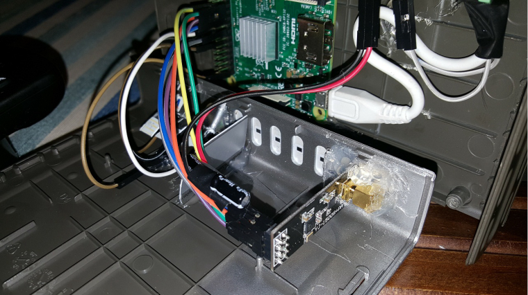
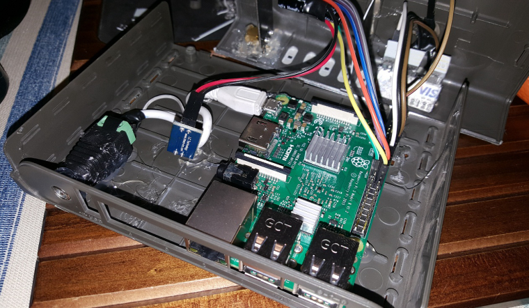
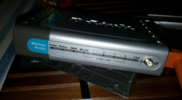
    • RE: RPi3 GPIO MySensors Gateway + LEDs + LNA Radio + DLink enclosure

      2_1498570291465_1 - Cópia (4).jpg 1_1498570291464_1 - Cópia (3).jpg 0_1498570291463_1 - Cópia (2).jpg

      posted in My Project
      OliverDog
      OliverDog
    • RE: RPi3 GPIO MySensors Gateway + LEDs + LNA Radio + DLink enclosure

      2_1498570265715_1 - Cópia (7).jpg 1_1498570265715_1 - Cópia (6).jpg 0_1498570265714_1 - Cópia (5).jpg

      posted in My Project
      OliverDog
      OliverDog
    • RPi3 GPIO MySensors Gateway + LEDs + LNA Radio + DLink enclosure

      Project built based on an old D-Link router enclosure.

      It is a Raspberry Pi 3 running Home Assistant with a RPi GPIO Gateway.

      Dedicated power supply for the radio, wired through a 5v to 3.3v regulator from the 3A 5V power supply.
      Ethernet and 2 USB ports available for connections.

      No soldering.
      Easy to build with some Hot Glue... took me 3 hours.

      0_1498570198661_1.jpg
      0_1498570220444_1 - Cópia.jpg

      posted in My Project
      OliverDog
      OliverDog
    • RE: [SOLVED] Multisensor Node stops working after some days...

      thanks @gohan I solved the problem by changing the power supply...

      Now I'm powering through USB using a phone charger... so I'll never know if it was a soldering problem on VIN or a low current problem from the other disassembled phone charger... but it is working now...

      Thanks for the help...

      posted in Troubleshooting
      OliverDog
      OliverDog
    • RE: [SOLVED] Multisensor Node stops working after some days...

      My power supply shows 900mah written on the case... can't measure because when tried with a multimeter, it stops the arduino power supply...

      But to change the power I should decide first if it worth keep trying through VIN connection or change to USB, which will be easier because could use a phone adapter without any mod or soldering...

      Does it do seem to be a power supply problem?

      Thanks

      posted in Troubleshooting
      OliverDog
      OliverDog
    • [SOLVED] Multisensor Node stops working after some days...

      Hi folks...

      I have a multisensor node on my baby's room created with:

      • Arduino Nano powered by wiring VIN from an old cell phone power adapter, which is connected on a wall switch, where I can turn it on and off easily if something is wrong...
      • MQ-2 gas sensor
      • DHT-11 for humidity and temp
      • 1 channel Relay which is connected to a wall AC power to turn on/off a Humidifier.

      When connected through the VIN it works during some days and them stop working as soon as I act the relay.
      If I use the relay the same day I turn it for the first time, it works, but after 2 or 3 days it stops working.
      When reseted, it sends the first value but when reach the relay presentation stop.

      When powered by USB all works fine, because of that I have nothing on the serial monitor...

      Is it a soldering problem in VIN terminal?
      If it is a power problem, why is it intermittent?

      This is my sketch:

      #define MY_DEBUG
      #define MY_RADIO_NRF24
      #define MY_NODE_ID 10
      
      #include <SPI.h>
      #include <MySensors.h>
      #include <DHT.h>  
      #include <Bounce2.h>
      
      #define RELAY_ON 0
      #define RELAY_OFF 1
      #define RELAY_MSG_ON 1
      #define RELAY_MSG_OFF 0
      #define RELAY_PIN  3
      #define BUTTON_PIN  2
      #define HUMIDITY_SENSOR_DIGITAL_PIN 5
      #define MQ_SENSOR_ANALOG_PIN         (0)  //define which analog input channel you are going to use
      
      #define RL_VALUE                     (1)     //define the load resistance on the board, in kilo ohms
      #define RO_CLEAN_AIR_FACTOR          (9.83)  //RO_CLEAR_AIR_FACTOR=(Sensor resistance in clean air)/RO,
      #define CALIBARAION_SAMPLE_TIMES     (50)    //define how many samples you are going to take in the calibration phase
      #define CALIBRATION_SAMPLE_INTERVAL  (500)   //define the time interal(in milisecond) between each samples in the
      #define READ_SAMPLE_INTERVAL         (50)    //define how many samples you are going to take in normal operation
      #define READ_SAMPLE_TIMES            (5)     //define the time interal(in milisecond) between each samples in
      #define GAS_LPG                      (0)
      #define GAS_CO                       (1)
      #define GAS_SMOKE                    (2)
      
      #define CHILD_ID_TEMP 3
      #define CHILD_ID_HUM 2
      #define CHILD_ID_MQ 0
      #define CHILD_ID_SWITCH 1
      
      unsigned long SLEEP_TIME = 6000; // Sleep time between reads (in loops)
      unsigned long sleeptimer = 5000;
      
      DHT dht;
      signed int lastTemp;
      signed int lastHum;
      int temp_correct;
      int hum_correct;
      int med_LPG;
      int med_CO;
      int med_SMOKE;
      bool metric = true; 
      Bounce debouncer = Bounce();
      bool state;
      bool initialValueSent = false;
      
      float Ro = 10000.0;    // this has to be tuned 10K Ohm
      int val = 0;           // variable to store the value coming from the sensor
      int valMQ = 0;
      int lastMQ = 0;
      float LPGCurve[3]  =  {2.3,0.21,-0.47};   //two points are taken from the curve.
      float COCurve[3]  =  {2.3,0.72,-0.34};    //two points are taken from the curve.
      float SmokeCurve[3] = {2.3,0.53,-0.44};   //two points are taken from the curve.
      
      MyMessage msg(CHILD_ID_MQ, V_LEVEL);
      MyMessage msgPrefix(CHILD_ID_MQ, V_UNIT_PREFIX);
      MyMessage msgHum(CHILD_ID_HUM, V_HUM);
      MyMessage msgTemp(CHILD_ID_TEMP, V_TEMP);
      MyMessage msgSwitch(CHILD_ID_SWITCH, V_LIGHT);
      
      void presentation()  
      { 
        sendSketchInfo("Baby", "1.0");
        wait(200);
        present(CHILD_ID_TEMP, S_TEMP);
        wait(200);
        present(CHILD_ID_HUM, S_HUM);
        wait(200);
        present(CHILD_ID_SWITCH, S_LIGHT);
        wait(200);
        present(CHILD_ID_MQ, S_AIR_QUALITY);
        metric = getControllerConfig().isMetric;
      }
      
      void setup()  
      { 
        pinMode(BUTTON_PIN, INPUT);
        digitalWrite(BUTTON_PIN, HIGH);
        debouncer.attach(BUTTON_PIN);
        debouncer.interval(5);
      
        // Make sure relays are off when starting up
        digitalWrite(RELAY_PIN, RELAY_OFF);
        pinMode(RELAY_PIN, OUTPUT);
      
        state = loadState(CHILD_ID_SWITCH);
        digitalWrite(RELAY_PIN, state?RELAY_ON:RELAY_OFF);
        
        dht.setup(HUMIDITY_SENSOR_DIGITAL_PIN); 
        wait(2000);
        signed int temperature = dht.getTemperature() + 0.5;
        wait(2000);
        signed int humidity = dht.getHumidity() + 0.5;
        wait(100);
        send(msgTemp.set(temperature));
        wait(100);
        send(msgHum.set(humidity));
        wait(100);
        send(msg.set("0"));
      
        Ro = MQCalibration(
                 MQ_SENSOR_ANALOG_PIN);         //Calibrating the sensor. Please make sure the sensor is in clean air
        send(msgPrefix.set("GCF"));
      }
      
      void loop()  { 
        if (!initialValueSent) {
          Serial.println("Sending initial value");
          send(msgSwitch.set(state?RELAY_MSG_ON:RELAY_MSG_OFF));
          Serial.println("Requesting initial value from controller");
          request(CHILD_ID_SWITCH, V_STATUS);
          wait(2000, C_SET, V_STATUS);
        }
        bool changed = debouncer.update();
        int value = debouncer.read();
        if (changed && value==0) {
          // Send new state and request ack back
          send(msgSwitch.set(state?false:true), true);
        }
        
        if (sleeptimer > SLEEP_TIME)    {
          sleeptimer= 0;
          // Fetch temperatures from DHT sensor
          signed int temperature = dht.getTemperature() + 0.5;
          if (isnan(temperature)) {
              Serial.println("Failed reading temperature from DHT");
          } else if (temperature != lastTemp) {
            lastTemp = temperature;
            if (!metric) {
              temperature = dht.toFahrenheit(temperature) + 0.5;
            }
            int temp_correct = temperature * 1.08;
            send(msgTemp.set(temp_correct));
            #ifdef MY_DEBUG
            Serial.print("Temp: ");
            Serial.println(temperature);
            #endif
          }
          
          // Fetch humidity from DHT sensor
          signed int humidity = dht.getHumidity() + 0.5;
          if (isnan(humidity)) {
              Serial.println("Failed reading humidity from DHT");
          } else if (humidity != lastHum) {
            lastHum = humidity;
            int hum_correct = 2.7 * humidity - 0.015 * humidity * humidity - 31.125;
            send(msgHum.set(hum_correct));
            #ifdef MY_DEBUG
            Serial.print("Umid: ");
            Serial.println(humidity);
            #endif
          }
      
          // Air Sensor - I wanted a composed number to knowing what kind of gas is reported. Everything bellow 80 is reported as 0, and increases from 111, where each number is about a different gas
       
          med_LPG = ((int) (MQGetGasPercentage(MQRead(MQ_SENSOR_ANALOG_PIN)/Ro,GAS_LPG) + 80) / 80) * 100;
          med_CO = ((int) (MQGetGasPercentage(MQRead(MQ_SENSOR_ANALOG_PIN)/Ro,GAS_CO) + 80) / 80) * 10;
          med_SMOKE = ((int) (MQGetGasPercentage(MQRead(MQ_SENSOR_ANALOG_PIN)/Ro,GAS_SMOKE) + 80) / 80);
          valMQ = med_LPG + med_CO + med_SMOKE;
          if (valMQ != lastMQ) {
            if (valMQ < 112) {
              send(msg.set(0));
            } else send(msg.set(valMQ));
            lastMQ = valMQ;
            Serial.print("Gas (LPG CO SMOKE): ");
            Serial.println(valMQ);
          }
        } else sleeptimer++;
        wait(10);
      }
      
      void receive(const MyMessage &message) {
        if (message.isAck()) {
           Serial.println("This is an ack from gateway");
        }
      
        if (message.type == V_LIGHT) {
          if (!initialValueSent) {
            Serial.println("Receiving initial value from controller");
            initialValueSent = true;
          }
          // Change relay state
          state = message.getBool();
          digitalWrite(RELAY_PIN, state?RELAY_ON:RELAY_OFF);
          saveState(CHILD_ID_SWITCH, state);
          send(msgSwitch.set(state?RELAY_MSG_ON:RELAY_MSG_OFF));
        }
      }
      
      
      /****************** MQResistanceCalculation ****************************************
      Input:   raw_adc - raw value read from adc, which represents the voltage
      Output:  the calculated sensor resistance
      Remarks: The sensor and the load resistor forms a voltage divider. Given the voltage
               across the load resistor and its resistance, the resistance of the sensor
               could be derived.
      ************************************************************************************/
      float MQResistanceCalculation(int raw_adc)
      {
        return ( ((float)RL_VALUE*(1023-raw_adc)/raw_adc));
      }
      
      /***************************** MQCalibration ****************************************
      Input:   mq_pin - analog channel
      Output:  Ro of the sensor
      Remarks: This function assumes that the sensor is in clean air. It use
               MQResistanceCalculation to calculates the sensor resistance in clean air
               and then divides it with RO_CLEAN_AIR_FACTOR. RO_CLEAN_AIR_FACTOR is about
               10, which differs slightly between different sensors.
      ************************************************************************************/
      float MQCalibration(int mq_pin)
      {
        int i;
        float val=0;
      
        for (i=0; i<CALIBARAION_SAMPLE_TIMES; i++) {          //take multiple samples
          val += MQResistanceCalculation(analogRead(mq_pin));
          delay(CALIBRATION_SAMPLE_INTERVAL);
        }
        val = val/CALIBARAION_SAMPLE_TIMES;                   //calculate the average value
      
        val = val/RO_CLEAN_AIR_FACTOR;                        //divided by RO_CLEAN_AIR_FACTOR yields the Ro
        //according to the chart in the datasheet
      
        return val;
      }
      /*****************************  MQRead *********************************************
      Input:   mq_pin - analog channel
      Output:  Rs of the sensor
      Remarks: This function use MQResistanceCalculation to caculate the sensor resistenc (Rs).
               The Rs changes as the sensor is in the different consentration of the target
               gas. The sample times and the time interval between samples could be configured
               by changing the definition of the macros.
      ************************************************************************************/
      float MQRead(int mq_pin)
      {
        int i;
        float rs=0;
      
        for (i=0; i<READ_SAMPLE_TIMES; i++) {
          rs += MQResistanceCalculation(analogRead(mq_pin));
          delay(READ_SAMPLE_INTERVAL);
        }
      
        rs = rs/READ_SAMPLE_TIMES;
      
        return rs;
      }
      
      /*****************************  MQGetGasPercentage **********************************
      Input:   rs_ro_ratio - Rs divided by Ro
               gas_id      - target gas type
      Output:  ppm of the target gas
      Remarks: This function passes different curves to the MQGetPercentage function which
               calculates the ppm (parts per million) of the target gas.
      ************************************************************************************/
      int MQGetGasPercentage(float rs_ro_ratio, int gas_id)
      {
        if ( gas_id == GAS_LPG ) {
          return MQGetPercentage(rs_ro_ratio,LPGCurve);
        } else if ( gas_id == GAS_CO ) {
          return MQGetPercentage(rs_ro_ratio,COCurve);
        } else if ( gas_id == GAS_SMOKE ) {
          return MQGetPercentage(rs_ro_ratio,SmokeCurve);
        }
      
        return 0;
      }
      
      /*****************************  MQGetPercentage **********************************
      Input:   rs_ro_ratio - Rs divided by Ro
               pcurve      - pointer to the curve of the target gas
      Output:  ppm of the target gas
      Remarks: By using the slope and a point of the line. The x(logarithmic value of ppm)
               of the line could be derived if y(rs_ro_ratio) is provided. As it is a
               logarithmic coordinate, power of 10 is used to convert the result to non-logarithmic
               value.
      ************************************************************************************/
      int  MQGetPercentage(float rs_ro_ratio, float *pcurve)
      {
        return (pow(10,( ((log10(rs_ro_ratio)-pcurve[1])/pcurve[2]) + pcurve[0])));
      }
      
      posted in Troubleshooting
      OliverDog
      OliverDog
    • RE: 💬 Building a Raspberry Pi Gateway

      @marceloaqno I already use Home Assistant with a Serial Gateway connected on pi USB.

      posted in Announcements
      OliverDog
      OliverDog
    • RE: 💬 Building a Raspberry Pi Gateway

      @marceloaqno WOWWW
      now I understood... but I think this is not clear on the build steps...
      I choose a Serial Gateway, but on that lines, they say:
      "If for some reason you can't use the GPIO pins of the Raspberry Pi, you could connect the radio to a arduino with the GatewaySerial sketch and feed the pi through a serial port:"

      So I assumed the serial gateway is the same I already use...
      So, where do I get directions to config a serial gateway with the radio attached to the GPIO?

      Thanks

      posted in Announcements
      OliverDog
      OliverDog
    • RE: 💬 Building a Raspberry Pi Gateway

      thaks @marceloaqno but I was wondering there was a new type of gateway named Raspberry Gateway, were we could connect the radio directly on the GPIO and config it locally, without internet, because of that I also would like to know if MQTT uses internet connection.
      I actually use a serial gateway connected to Pi USG and it works without internet...
      I just want to have only one device...
      Thanks

      posted in Announcements
      OliverDog
      OliverDog
    • RE: 💬 Building a Raspberry Pi Gateway

      trying to config on a Home Assistant Rpi.
      Sorry again for the newbie questions...!!!

      posted in Announcements
      OliverDog
      OliverDog
    • RE: 💬 Building a Raspberry Pi Gateway

      first sorry about the basics question but I think many people have the same questions and can't find the answers:
      After connecting the radio (including IRQ on 15pin) and the info LEDs to the GPIO, how to config it?

      1. Do I need to configure all the info on the same command, or can I send the command "./configure --" many times for different configs?
      2. Do I need to configure it as a MQTT gateway?
      3. Where did the 127.0.0.1 IP come from?
      4. Does MQTT use internet connection?
      5. Why do you talk about Serial Gateway here, once we have a specific type for it? this type is about using GPIO only, isn't it? That is confusing!!!
      posted in Announcements
      OliverDog
      OliverDog
    • RE: Safe In-Wall AC to DC Transformers??

      Hi guys.

      Did you get any conclusion at all?

      Between these both:
      http://www.electrodragon.com/product/ac-85-265v-dc-5v-power-module/
      https://pt.aliexpress.com/item/5-pcs-HLK-PM01-AC-DC-220V-to-5V-Step-Down-Power-Supply-Module-Intelligent-Household/32267273843.html?spm=2114.13010608.0.0.anpFsP

      ** the second seems genuine in the pictures.

      Is one safer than the other?
      Is one of them safe enough to in-wall use.

      posted in Hardware
      OliverDog
      OliverDog
    • RE: Multi RF433 Switches Node

      Perfect @BartE !!!

      Great job you did... you contributed greatly to a breakthrough in inexpensive home automation.

      Now we can buy the cheapest good finished glass RF in-wall home switches from Livolo and got total integration with All Home Automation Controllers, using one mysensors node.

      here is the final code, I added the remote code var

      // This skecth was created by @BartE from mysensors forum.
      // it was created to control 9 switches
      // livolo.h library necessary to work.
      // Just use a simple node + chinese cheap RF433 transmitter DATA plugged on Pin D8.
      
      #define MY_DEBUG 
      #define MY_RADIO_NRF24
      #include <SPI.h>
      #include <MySensors.h>
      #include <livolo.h>
      
      #define CHILD_ID 1
      
      Livolo livolo(8); //Digital pin you plugged your transmitter
      
      // now config your remote and button codes. Livolo codes are composed by "remote code, button code"
      // There are many codes already discovered, and you can test new codes or get your remote's code using the daleldalel skectch
      bool initValSent[]   = {false, false, false, false, false, false, false, false, false}; //as many as your switch number
      int livoloRemCode[]  = {5504, 5504, 5504, 7849, 7849, 7849, 17035, 17035, 17035}; //set remote livolo codes here
      int livoloSensCode[] = {16, 56, 8, 16, 8, 56, 16, 56, 8}; // Set buttons livolo codes here
      
      MyMessage msg(CHILD_ID, V_STATUS);
      
      void setup() {
        
      }
      
      void presentation()  {   
        sendSketchInfo("Livolo", "1.0");
        for (int sensor=1; sensor<=9; sensor++) { // change number 9 for the total switches number you want
          // (presents each sensor, S_BINARY type)
          present(sensor, S_BINARY);
        }
      }
      
      void loop() {
        for (int sensor=1; sensor<=9; sensor++) {  // change number 9 for the total switches number you want
          if (!initValSent[sensor-1]) {
            msg.setSensor(sensor);
            send(msg.set(false)); 
            Serial.print("Requesting initial value for sensor: ");
            Serial.println(sensor);
            request(sensor, V_STATUS);
            wait(2000, C_SET, V_STATUS);
          }
        }
      }
      
      void receive(const MyMessage &message) {
        switch (message.type) {
          case V_LIGHT:
             if (!initValSent[message.sensor-1]) {
                Serial.print("Receiving initial value from controller for sensor: ");
                initValSent[message.sensor-1] = true;
             } else {
                Serial.print("Receiving new value for sensor: ");
                livolo.sendButton(livoloRemCode[message.sensor-1], livoloSensCode[message.sensor-1]); // coded for each switch 
             }  
             Serial.println(message.sensor);  
             break;
        }
      }
      
      
      posted in Development
      OliverDog
      OliverDog
    • RE: Multi RF433 Switches Node

      In fact, it apear it does not ask for the value, it only receives new value.
      Here is the entire Serial Monitor until the infinite loop:

      TSM:INIT
      TSM:RADIO:OK
      TSP:ASSIGNID:OK (ID=19)
      TSM:FPAR
      TSP:MSG:SEND 19-19-255-255 s=255,c=3,t=7,pt=0,l=0,sg=0,ft=0,st=bc:
      TSP:MSG:READ 0-0-19 s=255,c=3,t=8,pt=1,l=1,sg=0:0
      TSP:MSG:FPAR RES (ID=0, dist=0)
      TSP:MSG:PAR OK (ID=0, dist=1)
      TSM:FPAR:OK
      TSM:ID
      TSM:CHKID:OK (ID=19)
      TSM:UPL
      TSP:PING:SEND (dest=0)
      TSP:MSG:SEND 19-19-0-0 s=255,c=3,t=24,pt=1,l=1,sg=0,ft=0,st=ok:1
      TSP:MSG:READ 0-0-19 s=255,c=3,t=25,pt=1,l=1,sg=0:1
      TSP:MSG:PONG RECV (hops=1)
      TSP:CHKUPL:OK
      TSM:UPL:OK
      TSM:READY
      TSP:MSG:SEND 19-19-0-0 s=255,c=3,t=15,pt=6,l=2,sg=0,ft=0,st=ok:0100
      TSP:MSG:SEND 19-19-0-0 s=255,c=0,t=17,pt=0,l=5,sg=0,ft=0,st=ok:2.0.0
      TSP:MSG:SEND 19-19-0-0 s=255,c=3,t=6,pt=1,l=1,sg=0,ft=0,st=ok:0
      TSP:MSG:READ 0-0-19 s=255,c=3,t=6,pt=0,l=1,sg=0:M
      TSP:MSG:SEND 19-19-0-0 s=255,c=3,t=11,pt=0,l=6,sg=0,ft=0,st=ok:Livolo
      TSP:MSG:SEND 19-19-0-0 s=255,c=3,t=12,pt=0,l=3,sg=0,ft=0,st=ok:1.0
      TSP:MSG:SEND 19-19-0-0 s=1,c=0,t=3,pt=0,l=0,sg=0,ft=0,st=ok:
      TSP:MSG:SEND 19-19-0-0 s=2,c=0,t=3,pt=0,l=0,sg=0,ft=0,st=ok:
      TSP:MSG:SEND 19-19-0-0 s=3,c=0,t=3,pt=0,l=0,sg=0,ft=0,st=ok:
      TSP:MSG:SEND 19-19-0-0 s=4,c=0,t=3,pt=0,l=0,sg=0,ft=0,st=ok:
      TSP:MSG:SEND 19-19-0-0 s=5,c=0,t=3,pt=0,l=0,sg=0,ft=0,st=ok:
      TSP:MSG:SEND 19-19-0-0 s=6,c=0,t=3,pt=0,l=0,sg=0,ft=0,st=ok:
      TSP:MSG:SEND 19-19-0-0 s=7,c=0,t=3,pt=0,l=0,sg=0,ft=0,st=ok:
      TSP:MSG:SEND 19-19-0-0 s=8,c=0,t=3,pt=0,l=0,sg=0,ft=0,st=ok:
      TSP:MSG:SEND 19-19-0-0 s=9,c=0,t=3,pt=0,l=0,sg=0,ft=0,st=ok:
      Request registration...
      TSP:MSG:SEND 19-19-0-0 s=255,c=3,t=26,pt=1,l=1,sg=0,ft=0,st=ok:2
      TSP:MSG:READ 0-0-19 s=255,c=3,t=27,pt=1,l=1,sg=0:1
      Node registration=1
      Init complete, id=19, parent=0, distance=1, registration=1
      TSP:MSG:SEND 19-19-0-0 s=1,c=1,t=2,pt=1,l=1,sg=0,ft=0,st=ok:0
      Requesting initial value for each sensor
      TSP:MSG:SEND 19-19-0-0 s=1,c=2,t=2,pt=0,l=0,sg=0,ft=0,st=ok:
      TSP:MSG:READ 0-0-19 s=1,c=1,t=2,pt=0,l=1,sg=0:0
      Receiving initial value from controller
      TSP:MSG:SEND 19-19-0-0 s=2,c=1,t=2,pt=1,l=1,sg=0,ft=0,st=ok:0
      Requesting initial value for each sensor
      TSP:MSG:SEND 19-19-0-0 s=2,c=2,t=2,pt=0,l=0,sg=0,ft=0,st=ok:
      TSP:MSG:READ 0-0-19 s=2,c=1,t=2,pt=0,l=1,sg=0:0
      Receiving initial value from controller
      TSP:MSG:SEND 19-19-0-0 s=3,c=1,t=2,pt=1,l=1,sg=0,ft=0,st=ok:0
      Requesting initial value for each sensor
      TSP:MSG:SEND 19-19-0-0 s=3,c=2,t=2,pt=0,l=0,sg=0,ft=0,st=ok:
      TSP:MSG:READ 0-0-19 s=3,c=1,t=2,pt=0,l=1,sg=0:0
      Receiving initial value from controller
      TSP:MSG:SEND 19-19-0-0 s=4,c=1,t=2,pt=1,l=1,sg=0,ft=0,st=ok:0
      Requesting initial value for each sensor
      TSP:MSG:SEND 19-19-0-0 s=4,c=2,t=2,pt=0,l=0,sg=0,ft=0,st=ok:
      TSP:MSG:READ 0-0-19 s=4,c=1,t=2,pt=0,l=1,sg=0:0
      Receiving initial value from controller
      TSP:MSG:SEND 19-19-0-0 s=5,c=1,t=2,pt=1,l=1,sg=0,ft=0,st=ok:0
      Requesting initial value for each sensor
      TSP:MSG:SEND 19-19-0-0 s=5,c=2,t=2,pt=0,l=0,sg=0,ft=0,st=ok:
      TSP:MSG:READ 0-0-19 s=5,c=1,t=2,pt=0,l=1,sg=0:0
      Receiving initial value from controller
      TSP:MSG:SEND 19-19-0-0 s=6,c=1,t=2,pt=1,l=1,sg=0,ft=0,st=ok:0
      Requesting initial value for each sensor
      TSP:MSG:SEND 19-19-0-0 s=6,c=2,t=2,pt=0,l=0,sg=0,ft=0,st=ok:
      TSP:MSG:READ 0-0-19 s=6,c=1,t=2,pt=0,l=1,sg=0:0
      Receiving initial value from controller
      TSP:MSG:SEND 19-19-0-0 s=7,c=1,t=2,pt=1,l=1,sg=0,ft=0,st=ok:0
      Requesting initial value for each sensor
      TSP:MSG:SEND 19-19-0-0 s=7,c=2,t=2,pt=0,l=0,sg=0,ft=0,st=ok:
      TSP:MSG:READ 0-0-19 s=7,c=1,t=2,pt=0,l=1,sg=0:0
      Receiving initial value from controller
      TSP:MSG:SEND 19-19-0-0 s=8,c=1,t=2,pt=1,l=1,sg=0,ft=0,st=ok:0
      Requesting initial value for each sensor
      TSP:MSG:SEND 19-19-0-0 s=8,c=2,t=2,pt=0,l=0,sg=0,ft=0,st=ok:
      TSP:MSG:READ 0-0-19 s=8,c=1,t=2,pt=0,l=1,sg=0:0
      Receiving initial value from controller
      TSP:MSG:SEND 19-19-0-0 s=9,c=1,t=2,pt=1,l=1,sg=0,ft=0,st=ok:0
      Requesting initial value for each sensor
      TSP:MSG:SEND 19-19-0-0 s=9,c=2,t=2,pt=0,l=0,sg=0,ft=0,st=ok:
      TSP:MSG:READ 0-0-19 s=9,c=1,t=2,pt=0,l=1,sg=0:0
      Receiving new value
      TSP:MSG:SEND 19-19-0-0 s=9,c=1,t=2,pt=1,l=1,sg=0,ft=0,st=ok:0
      Requesting initial value for each sensor
      TSP:MSG:SEND 19-19-0-0 s=9,c=2,t=2,pt=0,l=0,sg=0,ft=0,st=ok:
      TSP:MSG:READ 0-0-19 s=9,c=1,t=2,pt=0,l=1,sg=0:0
      Receiving new value
      
      posted in Development
      OliverDog
      OliverDog
    • RE: Multi RF433 Switches Node

      Nice @BartE
      Almost got it working...

      It keeps asking for the 9 sensor value and receiving the same value as a new value forever...

      Receiving new value
      TSP:MSG:SEND 19-19-0-0 s=9,c=1,t=2,pt=1,l=1,sg=0,ft=0,st=ok:0
      Requesting initial value for each sensor
      TSP:MSG:SEND 19-19-0-0 s=9,c=2,t=2,pt=0,l=0,sg=0,ft=0,st=ok:
      TSP:MSG:READ 0-0-19 s=9,c=1,t=2,pt=0,l=1,sg=0:0
      Receiving new value
      TSP:MSG:SEND 19-19-0-0 s=9,c=1,t=2,pt=1,l=1,sg=0,ft=0,st=ok:0
      Requesting initial value for each sensor
      TSP:MSG:SEND 19-19-0-0 s=9,c=2,t=2,pt=0,l=0,sg=0,ft=0,st=ok:
      TSP:MSG:READ 0-0-19 s=9,c=1,t=2,pt=0,l=1,sg=0:0
      Receiving new value
      TSP:MSG:SEND 19-19-0-0 s=9,c=1,t=2,pt=1,l=1,sg=0,ft=0,st=ok:0
      Requesting initial value for each sensor
      TSP:MSG:SEND 19-19-0-0 s=9,c=2,t=2,pt=0,l=0,sg=0,ft=0,st=ok:
      TSP:MSG:READ 0-0-19 s=9,c=1,t=2,pt=0,l=1,sg=0:0
      Receiving new value
      TSP:MSG:SEND 19-19-0-0 s=9,c=1,t=2,pt=1,l=1,sg=0,ft=0,st=ok:0
      Requesting initial value for each sensor
      TSP:MSG:SEND 19-19-0-0 s=9,c=2,t=2,pt=0,l=0,sg=0,ft=0,st=ok:
      TSP:MSG:READ 0-0-19 s=9,c=1,t=2,pt=0,l=1,sg=0:0
      Receiving new value
      TSP:MSG:SEND 19-19-0-0 s=9,c=1,t=2,pt=1,l=1,sg=0,ft=0,st=ok:0
      Requesting initial value for each sensor
      TSP:MSG:SEND 19-19-0-0 s=9,c=2,t=2,pt=0,l=0,sg=0,ft=0,st=ok:
      TSP:MSG:READ 0-0-19 s=9,c=1,t=2,pt=0,l=1,sg=0:0
      Receiving new value
      TSP:MSG:SEND 19-19-0-0 s=9,c=1,t=2,pt=1,l=1,sg=0,ft=0,st=ok:0

      posted in Development
      OliverDog
      OliverDog
    • RE: Multi RF433 Switches Node

      Thanks @mfalkvidd
      that ?: was killing my brain!! and I think I don't need conditional operator because the status need to be always off. It won't be 9 switches, but 9 momentary relays.

      I have already made a multi relay working, but my problem is not about creating and presenting 9 relays, but sending their initial status and confirming it was received by the gateway.

      I need to create 9 sensors (they won't send any data, just receive 9 different RF433 codes to reply), define an initial value for each one and confirm if the gateway got all those initial values before starting the receiving loop.

      And finally I need to config two types of received messages
      When receiving a initial value from gateway, I need to change initValSentX to true for each sensor.
      And when receiving a command from each virtual switch I need to reply a livolo.sendButton(REM_ID, BUT_ID) command.

      I think it is very simple but I can't figure out how coding it!
      Wrong way??

      #define MY_DEBUG 
      #define MY_RADIO_NRF24
      #include <SPI.h>
      #include <MySensors.h>
      #include <livolo.h>
      
      #define CHILD_ID 1
      
      Livolo livolo(8);
      
      bool initValSent1 = false;
      bool initValSent2 = false;
      bool initValSent3 = false;
      bool initValSent4 = false;
      bool initValSent5 = false;
      bool initValSent6 = false;
      bool initValSent7 = false;
      bool initValSent8 = false;
      bool initValSent9 = false;
      
      MyMessage msg(CHILD_ID, V_STATUS);
      
      void setup() {
        
      }
      
      void presentation()  {   
        sendSketchInfo("Livolo", "1.0");
        for (int sensor=1; sensor<=9; sensor++) { 
          // (presents each sensor, S_BINARY type)
          present(sensor, S_BINARY);
        }
      }
      
      void loop() {
        if (!initValSent1) {
          int value1;
          Serial.println("Sending initial value for each sensor");
          send(msg.set(value1==0)); 
          Serial.println("Requesting initial value for each sensor");
          request(CHILD_ID, V_STATUS);
          wait(2000, C_SET, V_STATUS);
        }
        if (!initValSent2) {
          int value2;
          Serial.println("Sending initial value for each sensor");
          send(msg.set(value2==0));
          Serial.println("Requesting initial value for each sensor");
          request(CHILD_ID, V_STATUS);
          wait(2000, C_SET, V_STATUS);
        }
      // thought making 7 more like these.
      
      }
      
      void receive(const MyMessage &message) {
        if (message ACTION FROM THE VIRTUAL SWITCH ON THE CONTROLLER) {
           if message from sensor 1
             livolo.sendButton(6400, 120); // coded for each sensor
           if message from sensor 2
             livolo.sendButton(6400, #70); // coded for each sensor
           // make 7 more like this
        if (message INITIAL VALUE ANSWER FROM THE GATEWAY ) {
           if (!initValSent1) {
             Serial.println("Receiving initial value from controller");
             initValSent1 = true;
           }
           // make 7 more like this
        }
      }
      
      
      posted in Development
      OliverDog
      OliverDog
    • Multi RF433 Switches Node

      Hi.
      I'm trying sketching myself for 6 days and just gave up...
      I read all the Library API and Serial API and can't understand this line syntax "send(msg.set(value==HIGH ? 1 : 0));"
      What do those "?" ":" mean?

      Objective: Control 9 Livolo branded RF433 switches from home assistant through a mysensors node build with a chinese RFTX 433Mhz.

      Home Assistant demands mysensor's node send presentation and an initial value for all the child_id, so they use a "initialValueSent" variable to check if the gateway got those initial values and request this value to assure they were been sent in the loop section.

      I've got the livolo's library for mysensors and joined some sketches and got success controlling 1 switch with this:

      #define MY_DEBUG 
      #define MY_RADIO_NRF24
      #include <SPI.h>
      #include <MySensors.h>
      #include <livolo.h>
      
      #define CHILD_ID 1
      
      Livolo livolo(8);   //tx 433 in the dig 8 pin
      
      bool initialValueSent = false;
      
      MyMessage msg(CHILD_ID, V_LIGHT);
      
      void setup() {
        
      }
      
      void presentation()  {   
        sendSketchInfo("Livolo", "1.0");
        present(CHILD_ID, S_LIGHT);
      }
      
      void loop() {
        if (!initialValueSent) {
          int value = 0;
          Serial.println("Sending initial value");
          send(msg.set(value==HIGH ? 1 : 0)); // how to I know which child_id is sending this?
          Serial.println("Requesting initial value from controller");
          request(CHILD_ID, V_LIGHT);
          wait(2000, C_SET, V_LIGHT);
        }
      }
      
      void receive(const MyMessage &message) {
        if (message.type==V_LIGHT) {
           livolo.sendButton(6400, 120);
           if (!initialValueSent) {
             Serial.println("Receiving initial value from controller");
             initialValueSent = true;
           }
        }
         
      }
      

      I can change that livolo line
      livolo.sendButton(6400, 120);
      for another (remote control ID, and button ID) and control the other switches.

      I tryed changing a multi relay sketch but I can't understand and did not find anywhere explain the syntax of sending messages from different child_id and making different actions for different child_id received messages from the gateway.

      So I need to check if all 9 initial values were received and make a void receive with livolo.sendButton(REM_ID, BUT_ID) based on each switch.

      posted in Development
      OliverDog
      OliverDog