@iotcrazy It is Jeedom, you can find some information here: http://www.mysensors.org/controller/jeedom
It use an RPI2 if you ant to make it yourself, and a major version will come during the week !
Posts made by Pierre P
-
RE: Sensebender Micro + button
-
RE: Sensebender Micro + button
I can't tell you for the moment, I haven't check the real voltage of the CR2032 at the beginning. I'll try to make two mesure between 30 days.
But my sketch is 1800000ms or 30min sleeping (if no-one press the button). Because it's a redundant information, my Jeedom controler have a meteo plugin who's working good. (i'll use it for the mini-night-temperature to have a message if there is glass on my car's windows). -
RE: Office plant monitoring
My node doesn't work anymore. Even with new set of accus. I will check again when I'll solder it.
-
RE: Office plant monitoring
A week.
New accus i think. I do it again but this time, i'm making voltage report with my voltmeter and a picture. -
RE: [security] Introducing signing support to MySensors
Thanks for the complet answer !
-
RE: Office plant monitoring
I'm already at 2.73Volts on my two AAA batteries. Is the last sketch a batteries killer ? With a 10 hours sleeping ??
-
RE: [security] Introducing signing support to MySensors
Isn't blacklisting cool too to use ?
Like, if we know the "name" of the sensor lost, we push it to the black list and voila ? This way, we don't have to put a long list a agreed sensors if we have only two nodes outside the house.
... I think. -
RE: Making a dual radio repeater
Thanks for the answer.
May we trick and use two arduino talking via serial ?
My controller doesn't support two gateway yet. -
Making a dual radio repeater
Hello everyone,
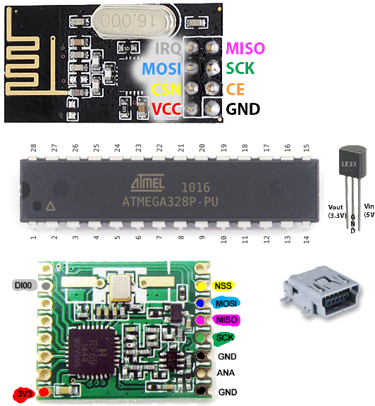
I would like to make a repeater with tow radio, because my gateway is 2.4Ghz, but i wan't to put outdoor sensors in 433Mhz.
BUT: as i'm not english native, i may haven't found the keyword to find this kind of project into the forum, is there anything like this ?
Thanks, and have a good day !
-
RE: Safe In-Wall AC to DC Transformers??
Do you want some tips to make "safe" crash tests ? Like putting it in a closed electrical box and switch on and off an old vacuum with no electronic ? Or make a shortcut make the relay ko... Because you cannot test that if you don't have a good electrical installation at home...
-
RE: In wall LCD Switch/Scene controller for MySensors
Thanks for the fast answer, I was thinking that you haven't used the "big" HLK. But, it seem it's there !
Sorry ! -
RE: In wall LCD Switch/Scene controller for MySensors
Seem nice !
And look like a KNX clim controler.Do you have a topic talking about your 230Vac/5Vdc solution ?
-
RE: [example] GPS Sensor
@drock1985 said:
Hey @Pierre-P
Yeah, you would need a new gateway for each radio type.
I found a new mysensors page ! here:
https://www.mysensors.org/download/sensor_api_15#create-repeating-nodesAdvanced initialization
It's also possible to construct an instance with RFM69 radio driver and/or enable signing support. You can choose one of the following radio drivers:
MyTransportNRF24 transport(RF24_CE_PIN, RF24_CS_PIN, RF24_PA_LEVEL_GW);
or
MyTransportRFM69 transport(RFM69_FREQUENCY, RFM69_NETWORKID, RF69_SPI_CS, RF69_IRQ_PIN, isRFM69HW, RF69_IRQ_NUM);
-
RE: "Internet Of Things" Security is hilariously broken and getting worse
For instance, with "orange" internet provider, i know how to redirect the port :1234 from internet to :80 intranet... but only once.
This is cool for 1 non editable port.
Sadly I don't think we can close the :80 port. It is (was) used by all the chat software.For the rest: never keep the box-user, never keep the box-software, try to never keep the box-ports. The bad guys KNOW this things. For a old but still used automation-device (witch can control big companies) it still the box-parameters. So... easy to enter into the programs.
It was the same for Americans money distributor !!! (now, the have a random password when send to the client) -
RE: "Internet Of Things" Security is hilariously broken and getting worse
@sundberg84 said:
I have a log on my controller port and get login attemps from tor routers a couple of times each week but its probably bots since they move on quickly.Could changing the default port ( :80 ) by something else be a good start ?
-
RE: Power from flowing water
This is not the same. The very first video can power out a big power. Then there is a box transforming it into 230Vac (or 110Vac) 50Hz.
The same box as for photovoltaïque or wind turbine.Then you have you product, who is only for low power device (like ours). But cannot feed an house.
Still, it can be cool for many mysensors device outdoor. -
RE: Infrared Temp Sensor
@Pierre-P said:
@scalz water temperature ? For baby bath ? I'll check if it work with my next coffee. Let me find my ir sensor.
For science !
https://www.youtube.com/watch?v=NPzUHAgRijc
ps: yes it's working -
RE: My Slim 2AA Battery Node
I've made it with that link: http://www.gammon.com.au/breadboard with no cristal.
-
RE: Infrared Temp Sensor
@scalz water temperature ? For baby bath ? I'll check if it work with my next coffee. Let me find my ir sensor.
I've got one for my 3d printer so:
3d printer safety control ! Because we should be next when printing, but we can't. -
RE: [example] GPS Sensor
@hek said:
- Attach it to your robot lawn mower to get a notification when it has stuck somewhere.
- Build a gps tracked pet collar (preferably using the HW RF69 module for long range operation). Used for geo fencing the dog to get a notification when it runs away. Or why not use it while hunting?
I'm in. For the mower.
For the radio, the lower frequency the better. But, we need a new gateway no ?
Or there is a trick, like a repeater node with two radio of different frequency ? -
RE: Infrared Temp Sensor
@hek said:
Maybe not super useful in a home automation system then...
By the power of hundred's of mysensors hacker's, I summon USE !
-
RE: Infrared Temp Sensor
Fire place temp !
I don't know how to say in English... Mass fireplace ? The one's where it still heat the house hours after the last flame ? -
RE: Power from flowing water
Interesting. But it should be easier to create 3.3v or 5v from the rain of the roofing...
Not everyone have a river next to the house. -
RE: My Slim 2AA Battery Node
@m26872 said:
Board releases:
- Version 2.0 (black) [order] Now designed in KiCad. Hopefully the "final" release.
Well, can I ask an update ? It's about the labels, couldn't we have them on the two faces ? It's always good to know where are Vcc and Gnd at first eye I think.
After all, the atmega and nrf are the only components that can't move to the other side. But even there, knowing the digital and analog pin should be useful ! -
RE: Office plant monitoring
Painted fork seem to work. 0% on dry heart, and now:
But the pourcentage of batterie seem to change a lot lot lot.
ps: i'll tell you if it's corroding.
-
RE: 110v-230v AC to Mysensors PCB board
@HenryWhite it mean that appart if you make a direct shortcut with a metal part, the only thing that came make the fuse blow, it is because of the HLK part.
So: fuse blow = HLK dead.
HLK dead = you don't need a resettable fuse, as you have to unsolder the HLK to repair the board (if no component seam to be dead after this one). -
RE: Gateway placement for people who sleep bad if the wi-fi network is on
I have a serial gateway. I've talked about wi-fi only for comparaison, but... It seem that it's not really comparable.
Thanks for your answers anyway !
-
RE: Gateway placement for people who sleep bad if the wi-fi network is on
Interesting but I've made tests with my wife... and i really know if the wifi was on or off without ask here.
But I'm okay that psychology is a main factor, but surely not the only one.
But yeah, Mysensors gateway is much more a listener than an emitter so... it may doesn't matter ?
-
RE: Can an ATMEGA have a footprint smaller than the Arduino Nano board?
It's because at the very beginning, it was for the 110v-230v-ac-to-mysensors-pcb-board. And the space taken by the arduino-nano in this particular project.
And i keep thinking this way.But there is no way that I put free cable without protection in hight voltage area !
And you people, don't do it too ! -
RE: Can an ATMEGA have a footprint smaller than the Arduino Nano board?
I was thinking of http://forum.mysensors.org/topic/1540/110v-230v-ac-to-mysensors-pcb-board
Sorry.
And it's not yours either ! -
RE: Can an ATMEGA have a footprint smaller than the Arduino Nano board?
I think i missed something... No arduino-nano pin are free to use in your project ?? I thought it was not "only"** a relay node.
Because if it's only that AND a humanly solderable PCB, the ATMEGA with cutted pin will do the job I think.** yeah, it's not only that, it's also a node that can feet in a power-box and without any wire. and trust me, i really like your project
-
RE: Office plant monitoring
@mfalkvidd said:
@Nicklas-Starkel last weekend one of my sensors broke. Both pins were completely corroded and broke
Did you try to just paint the sensors ?
I've seen that here: https://www.tindie.com/products/miceuz/i2c-soil-moisture-sensor/It doesn't work for me. I go double check the wiring. EDIT: not it's okay now. Great !
But is it possible to use A0-A1, A2-A3, A4-A5 on a atmega328P or there is the same pullup problem ?
-
RE: Can an ATMEGA have a footprint smaller than the Arduino Nano board?
Okay for the split.
The other resistor is for the temperature captor (same as here: https://www.mysensors.org/build/temp ). The design is nothing without at least one in or one out wired ! huhuhu.
I have 2x0.1µF only for the ATMEGA, one for digital side, one for analog side. I really don't know why two are needed. But I may ask. http://www.gammon.com.au/breadboard
And i've not inclued the capacitor for the NRF, i will put a 4.7µF near it. (not mentioned it because not part of the "atmegaboard").And why shorts ? http://www.openhardware.io/view/10/My-Slim-2AA-Battery-Node doesn't have some !
And with 10pins (power + nrf) to solder into a board (like yours), we have the possibility to "pull up" the ones we need out of the board, and solder directly on them. With heat-shrinkable tubing it seem safe. -
Can an ATMEGA have a footprint smaller than the Arduino Nano board?
I'm asking myself: does an ATMEGA could have a footprint smaller than the arduino nano board ?
For MySensors sketchs I mean. Because we can easily work with 8Mhz, and so, only need 4 composants:- ATMEGA328P-PU
- 10kohm resistor
- 0.1µF capacitor
- 0.1µF capactior
With that, a power supply between 2 and 3.3Vcc (because of the NRF, the ATMEGA can handle 5Vcc).
And we have more interrupt pin to play with. It seem to me that it may be an cool alternative design non ?
What do you think ?
-
Gateway placement for people who sleep bad if the wi-fi network is on
Hello all.
I'm just wondering if a repeater node with antenna outside the house (like, under the TV antenna) is better than a gateway with antenna inside, for people who sleep bad if the wi-fi network is on.Or... if the NRF24 is so much powerless (i don't know ow to say that in english) that it doesn't matter ?
-
RE: Sensebender Micro + button
I personaly think that it's quite good. When powered by FTDI, it found 3.00V.
And I have only add the "//" to BATT_SENSOR and it work good.
(you inverted the thing in the message just above).Thanks again for you help.
Now i work very good and very fast. I just have to check for adding an antenna to the controller. -
RE: Sensebender Micro + button
Voltage is not good (it's a new 3Vcc button cell) and batterie pourcentage is at 76%The battery voltage is not just minus 0.3V...
-
RE: Sensebender Micro + button
oh...
Just need to say use "2" decimals in the message and it's ok...The compilation work !
I'll try this afternoon the difference between #define BATT_SENSOR 199 and //#define BATT_SENSOR 199Thanks for your help !
-
RE: Sensebender Micro + button
Sorry i'm lost. I'm not as good for now.
(you may already see that) -
RE: Sensebender Micro + button
If I undefine: //#define BATT_SENSOR 199
it's working.
But your code still not 100% so we have to find why.
But... but, i think i'm making a mistake: yes i plan to use 3volts power. But, i don't want it as a sensor ! I wan't it as a battery level like the very first SensebenderMicro sketch. So... I have to undefine BATT_SENSOR ? And i will not have it set to 3Vcc=100% ?
-
RE: Sensebender Micro + button
BATT_SENSOR si declared.
... I think msgBatt is not.
Does it should be here ?// Sensor messages MyMessage msgHum(CHILD_ID_HUM, V_HUM); MyMessage msgTemp(CHILD_ID_TEMP, V_TEMP);
Wait not it's just under:
#ifdef BATT_SENSOR MyMessage msgBatt(BATT_SENSOR, V_VOLTAGE); #endif
-
RE: Sensebender Micro + button
@tbowmo "call of overloaded 'set(float&)' is ambiguous"
I don't know what it mean.
And i don't know why the very first sketch is working for you and not for me !/******************************************** * * Sends battery information (battery percentage) * * Parameters * - force : Forces transmission of a value * *******************************************/ void sendBattLevel(bool force) { if (force) lastBattery = -1; long vcc = readVcc(); if (vcc != lastBattery) { lastBattery = vcc; float siVolt = vcc / 1000; #ifdef BATT_SENSOR gw.send(msgBatt.set(siVolt)); #endif // Calculate percentage vcc = min(vcc, 3000L); // vcc max is 3000 vcc = vcc - 1900; // subtract 1.9V from vcc, as this is the lowest voltage we will operate at long percent = vcc / 11.0; gw.sendBatteryLevel(percent); transmission_occured = true; } } /*******************************************f```
-
RE: Sensebender Micro + button
@martinhjelmare there is a bug (for code bender and arduinoUI). It doesn't like siVolt. '"siVolt' was not declared in this scope"
your code:/******************************************** * * Sends battery information (battery percentage) * * Parameters * - force : Forces transmission of a value * *******************************************/ void sendBattLevel(bool force) { if (force) lastBattery = -1; long vcc = readVcc(); if (vcc != lastBattery) { lastBattery = vcc; siVolt = vcc / 1000; #ifdef BATT_SENSOR gw.send(msgBatt.set(siVolt)); #endif // Calculate percentage vcc = min(vcc, 3000L); // vcc max is 3000 vcc = vcc - 1900; // subtract 1.9V from vcc, as this is the lowest voltage we will operate at long percent = vcc / 11.0; gw.sendBatteryLevel(percent); transmission_occured = true; } } /*******************************************
old code
/******************************************** * * Sends battery information (battery percentage) * * Parameters * - force : Forces transmission of a value * *******************************************/ void sendBattLevel(bool force) { if (force) lastBattery = -1; long vcc = readVcc(); if (vcc != lastBattery) { lastBattery = vcc; #ifdef BATT_SENSOR gw.send(msgBatt.set(vcc)); #endif // Calculate percentage vcc = vcc - 1900; // subtract 1.9V from vcc, as this is the lowest voltage we will operate at long percent = vcc / 14.0; gw.sendBatteryLevel(percent); } }
How did you compil ?
-
RE: Sensebender Micro + button
Thanks a lot !
There is many improvements between the very first sketch !
And with OTA... Thanks ! -
Sensebender Micro + button
Hello all !
I like the way that this sketch: https://www.mysensors.org/hardware/micro work with Jeedom.
And I need a bell button that doesn't need a batterie per month.
So i've tried to mix with this sketch: https://www.mysensors.org/build/binary
But it's a fail. It only show the data once.The button is in D3. I may use D4 latter (as a secret button maybe). By using D3, we can use the ftdi port to power the circuit, and to cable the button. But then, i want to see how many time a button-cell can be used.
so:
How to use the interrupt fonction to wake up when pressing the button, and have a 10 minutes wake-up if no press ?
(And yeah, i could take off all the serial part)Thanks for helping !
ps: can't we write down the code ? It may be a bug from the forum but i can't go down...
/** * The MySensors Arduino library handles the wireless radio link and protocol * between your home built sensors/actuators and HA controller of choice. * The sensors forms a self healing radio network with optional repeaters. Each * repeater and gateway builds a routing tables in EEPROM which keeps track of the * network topology allowing messages to be routed to nodes. * * Created by Henrik Ekblad <henrik.ekblad@mysensors.org> * Copyright (C) 2013-2015 Sensnology AB * Full contributor list: https://github.com/mysensors/Arduino/graphs/contributors * * Documentation: http://www.mysensors.org * Support Forum: http://forum.mysensors.org * * This program is free software; you can redistribute it and/or * modify it under the terms of the GNU General Public License * version 2 as published by the Free Software Foundation. * ******************************* * * REVISION HISTORY * Version 1.0 - Henrik Ekblad * * DESCRIPTION * Default sensor sketch for Sensebender Micro module * Act as a temperature / humidity sensor by default. * * If A0 is held low while powering on, it will enter testmode, which verifies all on-board peripherals * * Battery voltage is as battery percentage (Internal message), and optionally as a sensor value (See defines below) * */ #include <MySensor.h> #include <Wire.h> #include <SI7021.h> #include <SPI.h> #include "utility/SPIFlash.h" #include <EEPROM.h> #include <sha204_lib_return_codes.h> #include <sha204_library.h> #include <RunningAverage.h> #include <avr/power.h> #include <Bounce2.h> // Define a static node address, remove if you want auto address assignment //#define NODE_ADDRESS 3 // Uncomment the line below, to transmit battery voltage as a normal sensor value //#define BATT_SENSOR 199 #define RELEASE "1.2" #define AVERAGES 2 // Child sensor ID's #define CHILD_ID_TEMP 1 #define CHILD_ID_HUM 2 // How many milli seconds between each measurement #define MEASURE_INTERVAL 600000 // FORCE_TRANSMIT_INTERVAL, this number of times of wakeup, the sensor is forced to report all values to the controller #define FORCE_TRANSMIT_INTERVAL 30 // When MEASURE_INTERVAL is 60000 and FORCE_TRANSMIT_INTERVAL is 30, we force a transmission every 30 minutes. // Between the forced transmissions a tranmission will only occur if the measured value differs from the previous measurement // HUMI_TRANSMIT_THRESHOLD tells how much the humidity should have changed since last time it was transmitted. Likewise with // TEMP_TRANSMIT_THRESHOLD for temperature threshold. #define HUMI_TRANSMIT_THRESHOLD 1 #define TEMP_TRANSMIT_THRESHOLD 1 // Pin definitions #define TEST_PIN A0 #define LED_PIN A2 #define ATSHA204_PIN 17 // A3 #define CHILD_ID_BP 3 #define BUTTON_PIN 3 // Arduino Digital I/O pin for button/reed switch //#define CHILD_ID 4 //#define BUTTON_PIN 4 // Arduino Digital I/O pin for button/reed switch const int sha204Pin = ATSHA204_PIN; atsha204Class sha204(sha204Pin); SI7021 humiditySensor; SPIFlash flash(8, 0x1F65); MySensor gw; // Sensor messages MyMessage msgHum(CHILD_ID_HUM, V_HUM); MyMessage msgTemp(CHILD_ID_TEMP, V_TEMP); MyMessage msgBP(CHILD_ID_BP,V_TRIPPED); Bounce debouncer = Bounce(); int oldValue=-1; #ifdef BATT_SENSOR MyMessage msgBatt(BATT_SENSOR, V_VOLTAGE); #endif // Global settings int measureCount = 0; int sendBattery = 0; boolean isMetric = true; boolean highfreq = true; // Storage of old measurements float lastTemperature = -100; int lastHumidity = -100; long lastBattery = -100; RunningAverage raHum(AVERAGES); /**************************************************** * * Setup code * ****************************************************/ void setup() { pinMode(LED_PIN, OUTPUT); digitalWrite(LED_PIN, LOW); Serial.begin(115200); Serial.print(F("Sensebender Micro FW ")); Serial.print(RELEASE); Serial.flush(); // First check if we should boot into test mode pinMode(TEST_PIN,INPUT); digitalWrite(TEST_PIN, HIGH); // Enable pullup if (!digitalRead(TEST_PIN)) testMode(); // Make sure that ATSHA204 is not floating pinMode(ATSHA204_PIN, INPUT); digitalWrite(ATSHA204_PIN, HIGH); digitalWrite(TEST_PIN,LOW); digitalWrite(LED_PIN, HIGH); #ifdef NODE_ADDRESS gw.begin(NULL, NODE_ADDRESS, false); #else gw.begin(NULL,AUTO,false); #endif // Setup the button pinMode(BUTTON_PIN,INPUT); // Activate internal pull-up digitalWrite(BUTTON_PIN,HIGH); // After setting up the button, setup debouncer debouncer.attach(BUTTON_PIN); debouncer.interval(5); humiditySensor.begin(); digitalWrite(LED_PIN, LOW); Serial.flush(); Serial.println(F(" - Online!")); gw.sendSketchInfo("Sensebender Micro", RELEASE); gw.present(CHILD_ID_TEMP,S_TEMP); gw.present(CHILD_ID_HUM,S_HUM); // Register binary input sensor to gw (they will be created as child devices) gw.present(CHILD_ID_BP, S_DOOR); #ifdef BATT_SENSOR gw.present(BATT_SENSOR, S_POWER); #endif isMetric = gw.getConfig().isMetric; Serial.print(F("isMetric: ")); Serial.println(isMetric); raHum.clear(); sendTempHumidityMeasurements(false); sendBattLevel(false); } /*********************************************** * * Main loop function * ***********************************************/ void loop() { measureCount ++; sendBattery ++; bool forceTransmit = false; if ((measureCount == 5) && highfreq) { clock_prescale_set(clock_div_8); // Switch to 1Mhz for the reminder of the sketch, save power. highfreq = false; } if (measureCount > FORCE_TRANSMIT_INTERVAL) { // force a transmission forceTransmit = true; measureCount = 0; } gw.process(); sendTempHumidityMeasurements(forceTransmit); if (sendBattery > 60) { sendBattLevel(forceTransmit); // Not needed to send battery info that often sendBattery = 0; } // début du rajout { debouncer.update(); // Get the update value int value = debouncer.read(); if (value != oldValue) { // Send in the new value gw.send(msgBP.set(value==HIGH ? 1 : 0)); oldValue = value; } } // fin du rajout gw.sleep(MEASURE_INTERVAL); } /********************************************* * * Sends temperature and humidity from Si7021 sensor * * Parameters * - force : Forces transmission of a value (even if it's the same as previous measurement) * *********************************************/ void sendTempHumidityMeasurements(bool force) { bool tx = force; si7021_env data = humiditySensor.getHumidityAndTemperature(); float oldAvgHum = raHum.getAverage(); raHum.addValue(data.humidityPercent); float diffTemp = abs(lastTemperature - (isMetric ? data.celsiusHundredths : data.fahrenheitHundredths)/100); float diffHum = abs(oldAvgHum - raHum.getAverage()); Serial.print(F("TempDiff :"));Serial.println(diffTemp); Serial.print(F("HumDiff :"));Serial.println(diffHum); if (isnan(diffHum)) tx = true; if (diffTemp > TEMP_TRANSMIT_THRESHOLD) tx = true; if (diffHum >= HUMI_TRANSMIT_THRESHOLD) tx = true; if (tx) { measureCount = 0; float temperature = (isMetric ? data.celsiusHundredths : data.fahrenheitHundredths) / 100.0; int humidity = data.humidityPercent; Serial.print("T: ");Serial.println(temperature); Serial.print("H: ");Serial.println(humidity); gw.send(msgTemp.set(temperature,1)); gw.send(msgHum.set(humidity)); lastTemperature = temperature; lastHumidity = humidity; } } /******************************************** * * Sends battery information (battery percentage) * * Parameters * - force : Forces transmission of a value * *******************************************/ void sendBattLevel(bool force) { if (force) lastBattery = -1; long vcc = readVcc(); if (vcc != lastBattery) { lastBattery = vcc; #ifdef BATT_SENSOR gw.send(msgBatt.set(vcc)); #endif // Calculate percentage vcc = vcc - 1900; // subtract 1.9V from vcc, as this is the lowest voltage we will operate at long percent = vcc / 14.0; gw.sendBatteryLevel(percent); } } /******************************************* * * Internal battery ADC measuring * *******************************************/ long readVcc() { // Read 1.1V reference against AVcc // set the reference to Vcc and the measurement to the internal 1.1V reference #if defined(__AVR_ATmega32U4__) || defined(__AVR_ATmega1280__) || defined(__AVR_ATmega2560__) ADMUX = _BV(REFS0) | _BV(MUX4) | _BV(MUX3) | _BV(MUX2) | _BV(MUX1); #elif defined (__AVR_ATtiny24__) || defined(__AVR_ATtiny44__) || defined(__AVR_ATtiny84__) ADMUX = _BV(MUX5) | _BV(MUX0); #elif defined (__AVR_ATtiny25__) || defined(__AVR_ATtiny45__) || defined(__AVR_ATtiny85__) ADcdMUX = _BV(MUX3) | _BV(MUX2); #else ADMUX = _BV(REFS0) | _BV(MUX3) | _BV(MUX2) | _BV(MUX1); #endif delay(2); // Wait for Vref to settle ADCSRA |= _BV(ADSC); // Start conversion while (bit_is_set(ADCSRA,ADSC)); // measuring uint8_t low = ADCL; // must read ADCL first - it then locks ADCH uint8_t high = ADCH; // unlocks both long result = (high<<8) | low; result = 1125300L / result; // Calculate Vcc (in mV); 1125300 = 1.1*1023*1000 return result; // Vcc in millivolts } /**************************************************** * * Verify all peripherals, and signal via the LED if any problems. * ****************************************************/ void testMode() { uint8_t rx_buffer[SHA204_RSP_SIZE_MAX]; uint8_t ret_code; byte tests = 0; digitalWrite(LED_PIN, HIGH); // Turn on LED. Serial.println(F(" - TestMode")); Serial.println(F("Testing peripherals!")); Serial.flush(); Serial.print(F("-> SI7021 : ")); Serial.flush(); if (humiditySensor.begin()) { Serial.println(F("ok!")); tests ++; } else { Serial.println(F("failed!")); } Serial.flush(); Serial.print(F("-> Flash : ")); Serial.flush(); if (flash.initialize()) { Serial.println(F("ok!")); tests ++; } else { Serial.println(F("failed!")); } Serial.flush(); Serial.print(F("-> SHA204 : ")); ret_code = sha204.sha204c_wakeup(rx_buffer); Serial.flush(); if (ret_code != SHA204_SUCCESS) { Serial.print(F("Failed to wake device. Response: ")); Serial.println(ret_code, HEX); } Serial.flush(); if (ret_code == SHA204_SUCCESS) { ret_code = sha204.getSerialNumber(rx_buffer); if (ret_code != SHA204_SUCCESS) { Serial.print(F("Failed to obtain device serial number. Response: ")); Serial.println(ret_code, HEX); } else { Serial.print(F("Ok (serial : ")); for (int i=0; i<9; i++) { if (rx_buffer[i] < 0x10) { Serial.print('0'); // Because Serial.print does not 0-pad HEX } Serial.print(rx_buffer[i], HEX); } Serial.println(")"); tests ++; } } Serial.flush(); Serial.println(F("Test finished")); if (tests == 3) { Serial.println(F("Selftest ok!")); while (1) // Blink OK pattern! { digitalWrite(LED_PIN, HIGH); delay(200); digitalWrite(LED_PIN, LOW); delay(200); } } else { Serial.println(F("----> Selftest failed!")); while (1) // Blink FAILED pattern! Rappidly blinking.. { } } }
-
RE: My Slim 2AA Battery Node
@m26872 I see it in the BOM. But now, i can't see where it goes (5 hours... I ask a question, and 5 hours later I can't see what i was talking about....)
C4 is cool for the NRF pic of tension, but -just for information- it could be wherever between 0Vcc and 5Vcc, not necessarily near the NRF ?
As an electrician, and not an electronician, I don't understand why so many 0.1uF capacitor are needed (but i put them too) as we can see in MySlimNode2-sch.pdf that they are virtually at the same place...
Thanks for the answer !
-
RE: My Slim 2AA Battery Node
Hello,
This board is GREAT. But why C5 ave to be different from C1 C2 C3 ?