Can an ATMEGA have a footprint smaller than the Arduino Nano board?
-
I'm asking myself: does an ATMEGA could have a footprint smaller than the arduino nano board ?
For MySensors sketchs I mean. Because we can easily work with 8Mhz, and so, only need 4 composants:- ATMEGA328P-PU
- 10kohm resistor
- 0.1µF capacitor
- 0.1µF capactior
With that, a power supply between 2 and 3.3Vcc (because of the NRF, the ATMEGA can handle 5Vcc).
And we have more interrupt pin to play with. It seem to me that it may be an cool alternative design non ?
What do you think ?
@Pierre-P Wow! That's some serious 3D design! ;-)
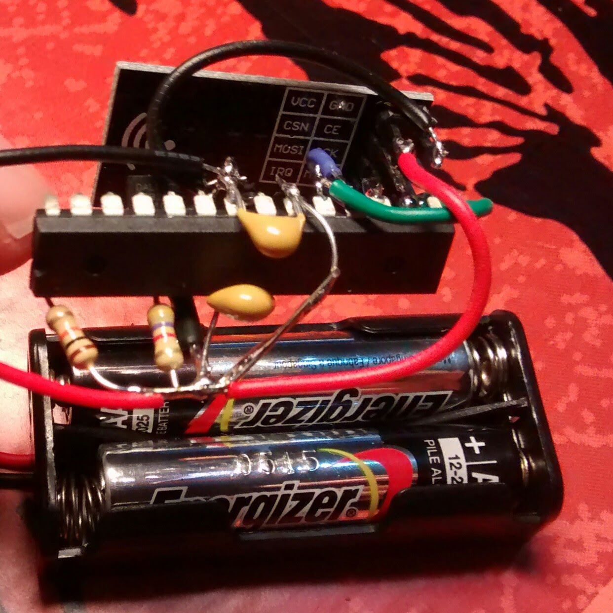
This setup can indeed result in a very small sensor, but how are you planning to put this in some housing, without creating shorts?Btw. I see 2 resistors: one to pull up /reset, what's the other one used for?
Why do you need 2 x 0.1uF? The nRF24 module has its own and I doubt if you really need one for the AtMega when battery powering... -
I'm asking myself: does an ATMEGA could have a footprint smaller than the arduino nano board ?
For MySensors sketchs I mean. Because we can easily work with 8Mhz, and so, only need 4 composants:- ATMEGA328P-PU
- 10kohm resistor
- 0.1µF capacitor
- 0.1µF capactior
With that, a power supply between 2 and 3.3Vcc (because of the NRF, the ATMEGA can handle 5Vcc).
And we have more interrupt pin to play with. It seem to me that it may be an cool alternative design non ?
What do you think ?
-
Okay for the split.
The other resistor is for the temperature captor (same as here: https://www.mysensors.org/build/temp ). The design is nothing without at least one in or one out wired ! huhuhu.
I have 2x0.1µF only for the ATMEGA, one for digital side, one for analog side. I really don't know why two are needed. But I may ask. http://www.gammon.com.au/breadboard
And i've not inclued the capacitor for the NRF, i will put a 4.7µF near it. (not mentioned it because not part of the "atmegaboard").And why shorts ? http://www.openhardware.io/view/10/My-Slim-2AA-Battery-Node doesn't have some !
And with 10pins (power + nrf) to solder into a board (like yours), we have the possibility to "pull up" the ones we need out of the board, and solder directly on them. With heat-shrinkable tubing it seem safe. -
Okay for the split.
The other resistor is for the temperature captor (same as here: https://www.mysensors.org/build/temp ). The design is nothing without at least one in or one out wired ! huhuhu.
I have 2x0.1µF only for the ATMEGA, one for digital side, one for analog side. I really don't know why two are needed. But I may ask. http://www.gammon.com.au/breadboard
And i've not inclued the capacitor for the NRF, i will put a 4.7µF near it. (not mentioned it because not part of the "atmegaboard").And why shorts ? http://www.openhardware.io/view/10/My-Slim-2AA-Battery-Node doesn't have some !
And with 10pins (power + nrf) to solder into a board (like yours), we have the possibility to "pull up" the ones we need out of the board, and solder directly on them. With heat-shrinkable tubing it seem safe.@Pierre-P Now you mention it I see the DS18B20 just below the 'wifi' logo on the nRF. Wouldn't be much of a sensor without it...
I personally never put an extra cap on the nRF when battery powering a sensor. IMHO the batteries can deliver enough power for the current peaks when the nRF is active.
The slim battery node you're referring to uses a PCB to mount the ATMega. The loose wires you have can easily bend and cause shorts.
I don't say it can't be done (e.g. using heat shrink tubing or drowning the whole thing in hot glue) but I'm just eager to know how you plan to put it all together! -
I think i missed something... No arduino-nano pin are free to use in your project ?? I thought it was not "only"** a relay node.
Because if it's only that AND a humanly solderable PCB, the ATMEGA with cutted pin will do the job I think.** yeah, it's not only that, it's also a node that can feet in a power-box and without any wire. and trust me, i really like your project :+1:
-
I was thinking of http://forum.mysensors.org/topic/1540/110v-230v-ac-to-mysensors-pcb-board
Sorry.
And it's not yours either ! :sweat_smile: -
I was thinking of http://forum.mysensors.org/topic/1540/110v-230v-ac-to-mysensors-pcb-board
Sorry.
And it's not yours either ! :sweat_smile: -
It's because at the very beginning, it was for the 110v-230v-ac-to-mysensors-pcb-board. And the space taken by the arduino-nano in this particular project.
And i keep thinking this way.But there is no way that I put free cable without protection in hight voltage area !
And you people, don't do it too ! :boom:
Hello! It looks like you're interested in this conversation, but you don't have an account yet.
Getting fed up of having to scroll through the same posts each visit? When you register for an account, you'll always come back to exactly where you were before, and choose to be notified of new replies (either via email, or push notification). You'll also be able to save bookmarks and upvote posts to show your appreciation to other community members.
With your input, this post could be even better 💗
Register Login