Navigation

    • Register
    • Login
    • Search
    • OpenHardware.io
    • Categories
    • Recent
    • Tags
    • Popular
    1. Home
    2. Spanners
    3. Best
    • Profile
    • Following
    • Followers
    • Topics
    • Posts
    • Best
    • Groups

    Best posts made by Spanners

    • RE: What did you build today (Pictures) ?

      Today I built a new Ethernet Gateway.

      Using a Freetrionics Ethermega - Fixed SPI bus, so no soft SPI and I can use MY_RX_MESSAGE_BUFFER_FEATURE. PoE, improved voltage regulator design so I can run the amplified NRF24 with MY_RF24_PA_LEVEL RF24_PA_HIGH.

      Under the radio is a small prototyping area with capacitor for the radio and an ATSHA204A - because one day I swear I will implement signing.

      Slightly modified Gateway sketch that writes successful DHCP IP addresses to EEPROM. I assign a static address on my router. If there's a power failure, the gateway will start up with last address - router takes ages to come online.

      Fired up the X-carve to cut the aluminium chassis, which has added benefit of shielding the NRF radio as well. The complicated cutout on the front was to allow air intake for the fan. Was supposed to just be a grille, but after a couple of beers I got too cute for my own good. Took 2 hours to cut that. 🙂

      0_1522406220035_IMG_5814.JPG
      1_1522406220036_IMG_5816.JPG
      2_1522406220036_IMG_5817.JPG

      posted in General Discussion
      Spanners
      Spanners
    • RE: Irrigation Controller (up to 16 valves with Shift Registers)

      @dbemowsk Thanks, that clears it up.

      I ended up going with a Mega with LCD Shield and used additional digital pins for the relays. I wanted to enable the IRQ buffering for the NRF radio and some LCDText devices to report back to Vera some status information. Sadly I had to use Strings as I struggled to get char[] arrays to work. Got a bit hard to fit onto the memory of the Pro Mini.

      I needed 2 controllers for front and back, one with Master Valve setup. The back reticulation is an extension of front zone - so Vera makes sure the front controller supplies water when the back controller is active.

      alt text

      If there's interest I'll post the code, maybe someone with better skills than me could rewrite the String section - I don't know if I'll have issues with memory fragmentation yet. Only installed them today.

      A big thank you to @petewill and @BulldogLowell for sharing their code and design.

      posted in My Project
      Spanners
      Spanners
    • First NRF Project (Ebyte nRF52832) device seems to hang after programming

      Hi All,

      I'm hoping some of you can help me out, I've trawled the internet for the past week and the 1700 posts in the NRF Action thread. I've managed to at least get my NRF to program (I think), but when I load sketches on I don't get any action.
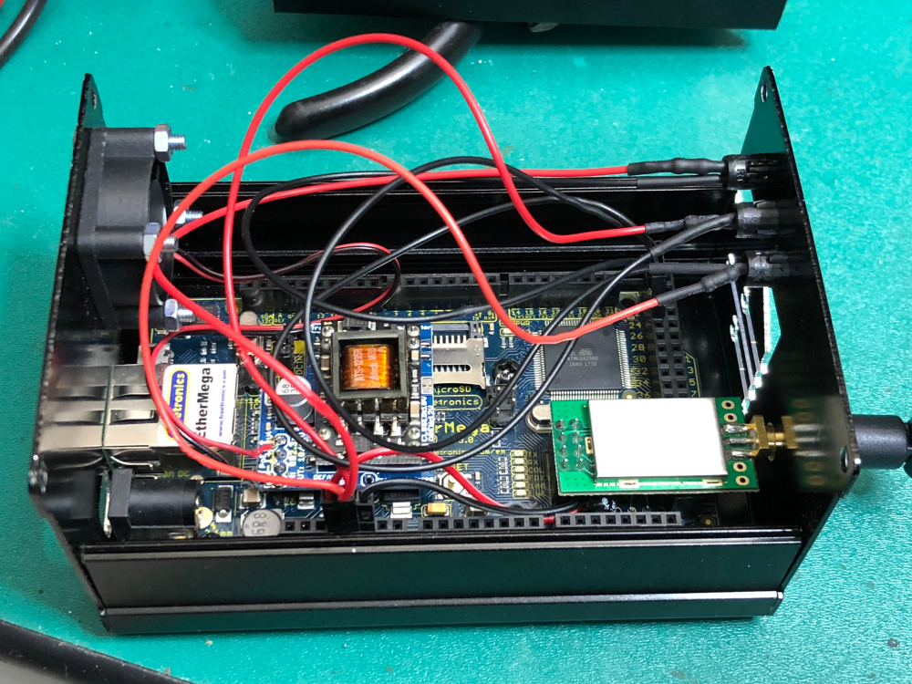
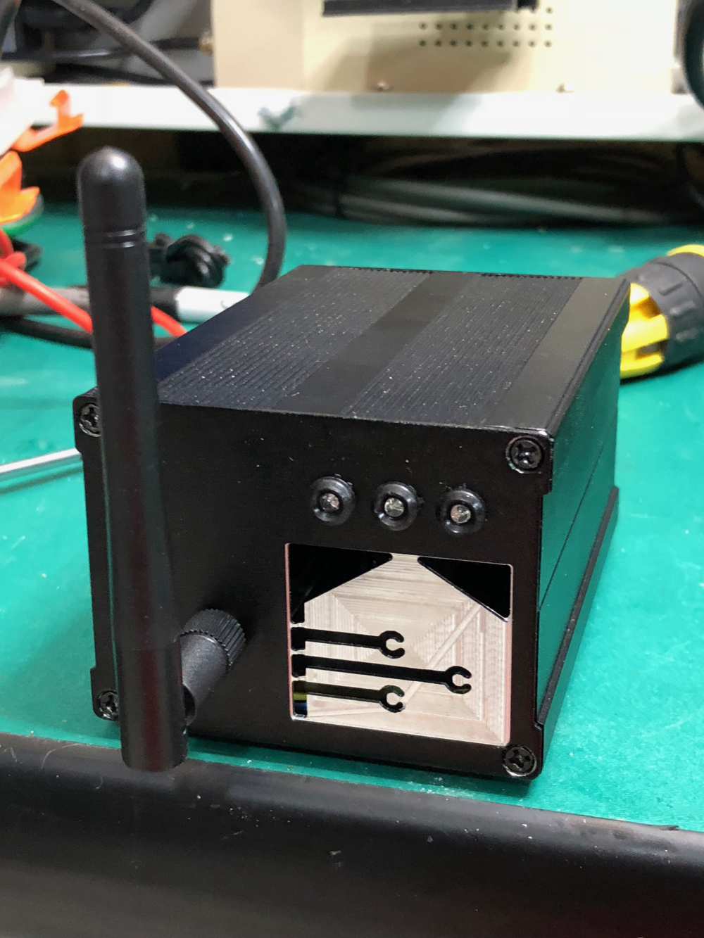
      The setup:

      • Ebyte nRF52832 E73-2G4M04S module - have 5, tried 2 so far

      • @NeverDie Small Breakout board (with the SMD components) https://www.openhardware.io/view/471/Ebyte-nRF52832-Small-Breakout-Board

      • Segger J-Link EDU (real one), JTAG to ARM cable adaptor

      • Windows 10, Arduino IDE 1.8.5

      • Installed board managers and NRF-y things as outlined https://www.openhardware.io/view/376/MySensors-NRF5-Platform AND https://forum.mysensors.org/topic/9266/guide-nrf5-nrf51-nrf52-for-beginners

      • IDE settings MyboardNRF5 nRF52832, None, Crystal Oscillator, Reset:Don't Enable

      Ok, first thing I was unable to do was burn the bootloader or upload any sketches like the erase_all example. I ended up using Nordic's nrfjprog to unlock the chip via $ nrfjprog -f NRF52 --recover, but this requires the use of a JLink debugger with the JLink driver (not WinUSB).

      After doing that, success... have been able to upload sketches, and on @NeverDie 's board, the LED lights up. If I wipe the NRF again, LED is off.

      My test sketch is the Blink_Serial_Demo_v001 which was posted with the board schematics. It needed some modification, but it compiles and I believe is faithful to the pinouts for the breakout board.

      /*
       * This example sketch shows how you can manage the nRF5 pin mapping as part of your code.
       * You can use the method for any nRF51822 or nRF52832 board or module.
       * 
       * Most components, like UART, SPI, Wire Bus, of the nRF5 series chips don't
       * have a fixed pin mapping. There are some pins with restrictions like analog
       * inputs, NFC or pins near the radio module. Please refer the latest
       * documentation about pin restrictions at http://infocenter.nordicsemi.com 
       * 
       * To use the custom pin mapping you have to do following steps:
       * 
       * 1. Install "arduino-nrf5" like described at
       *    https://github.com/sandeepmistry/arduino-nRF5/
       * 2. Install the "My Sensors nRF5 Boards" with the board manager like
       *    explained at https://github.com/mysensors/ArduinoBoards
       * 3. Copy the files "MyNRF5Board.cpp" and "MyNRF5Board.h" from
       *    "MyNRF5Board" example into your sketch.
       * 4. Modify pin mappings in "MyNRF5Board.cpp" and "MyNRF5Board.h" to fit
       *    your requirements.
       * 5. Select "MyNRF5Board nrf52832" or "MyNRF5Board nrf52822" as your board.
       *    Choose the correct parameters and programmer in the Tools menu.
       */
      
      //Simple program to demonstrate that both the LED and Serial are working correctly on the breakout board:
      // https://www.openhardware.io/view/471/Ebyte-nRF52832-Small-Breakout-Board
      //Note: Compile and upload from Arduino IDE using "MyNRF5Board nRF52832" as the board.
      //
      // Many thanks to d00616 for this framework!
      
      //#define MY_GATEWAY_SERIAL
      #define MY_RADIO_NRF5_ESB
      #define MY_DEBUG
      #define MY_NODE_ID 254
      
      
      #include <nrf.h>
      #include <MySensors.h>
      
      void setup() {
        Serial.begin(115200);
        hwPinMode(LED_BUILTIN,OUTPUT_H0H1);
      }
      
      void presentation()
      {
        
      }
      
      void loop() {
        Serial.println("HIGH");
        digitalWrite(LED_BUILTIN,HIGH);
        delay(1000);
        Serial.println("LOW");
        digitalWrite(LED_BUILTIN,LOW);
        delay(1000);
      }
      
      /*
        If you don't use an nRF5 board, you can ignore this file.
      
        This file was part of the "My Sensors nRF5 Boards" board repository
        available at https://github.com/mysensors/ArduinoBoards If you have
        questions, please refer the documentation at
        https://github.com/mysensors/ArduinoHwNRF5 first.
      
        This file is compatible with ArduinoHwNRF5 >= 0.2.0
      
        This file allows you to change the pins of internal hardware, like the
        serial port, SPI bus or Wire bus.
      
        All pins referenced here are mapped via the "g_ADigitalPinMap" Array
        defined in "MyBoardNRF5.cpp" to pins of the MCU.
        
        As an example, if you have at the third position in "g_ADigitalPinMap" the
        12, then all ports referenced in Arduino with 2 are mapped to P0.12. If you
        don't change the "g_ADigitalPinMap" Array, the Arduino pins 0..31 are
        translated to P0.00..P0..31.
         
        ###########################################################################
       
        This file is compatible with ArduinoHwNRF5 > 0.1.0
        Copyright (c) 2014-2015 Arduino LLC.  All right reserved.
        Copyright (c) 2016 Sandeep Mistry. All right reserved.
        Copyright (c) 2017 Sensnology AB. All right reserved.
      
        This library is free software; you can redistribute it and/or
        modify it under the terms of the GNU Lesser General Public
        License as published by the Free Software Foundation; either
        version 2.1 of the License, or (at your option) any later version.
        This library is distributed in the hope that it will be useful,
        but WITHOUT ANY WARRANTY; without even the implied warranty of
        MERCHANTABILITY or FITNESS FOR A PARTICULAR PURPOSE.
        See the GNU Lesser General Public License for more details.
        You should have received a copy of the GNU Lesser General Public
        License along with this library; if not, write to the Free Software
        Foundation, Inc., 51 Franklin St, Fifth Floor, Boston, MA  02110-1301  USA
      */
      
      #ifndef _MYBOARDNRF5_H_
      #define _MYBOARDNRF5_H_
      
      #ifdef __cplusplus
      extern "C"
      {
      #endif // __cplusplus
      
      // Number of pins defined in PinDescription array
      #define PINS_COUNT           (32u)
      #define NUM_DIGITAL_PINS     (32u)
      #define NUM_ANALOG_INPUTS    (8u)
      #define NUM_ANALOG_OUTPUTS   (8u)
      
      /* 
       *  LEDs
       *  
       *  This is optional
       *  
       *  With My Sensors, you can use
       *  hwPinMode() instead of pinMode()
       *  hwPinMode() allows to use advanced modes like OUTPUT_H0H1 to drive LEDs.
       *  https://github.com/mysensors/MySensors/blob/development/drivers/NRF5/nrf5_wiring_constants.h
       *
       */
      #define PIN_LED1                (11)
      //#define PIN_LED1                (8)
      // #define PIN_LED2                (25)
      // #define PIN_LED3                (26)
      // #define PIN_LED4                (27)
      // #define PIN_LED5                (12)
      // #define PIN_LED6                (14)
      // #define PIN_LED7                (15)
      // #define PIN_LED8                (16)
      // #define USER_LED             	 (PIN_LED2)
      // #define RED_LED                 (PIN_LED3)
      // #define GREEN_LED            	 (PIN_LED4)
      // #define BLUE_LED			           (PIN_LED1)
      // #define BLE_LED                 BLUE_LED
      #define LED_BUILTIN          PIN_LED1
      
      /* 
       *  Buttons
       *  
       *  This is optional
       */
      // #define PIN_BUTTON1             (3)
      // #define PIN_BUTTON2             (4)
      // #define PIN_BUTTON3             (5)
      // #define PIN_BUTTON4             (6)
      // #define PIN_BUTTON5             (7)
      // #define PIN_BUTTON6             (8)
      // #define PIN_BUTTON7             (9)
      // #define PIN_BUTTON8             (10)
      
      /* 
       * Analog ports
       *  
       * If you change g_APinDescription, replace PIN_AIN0 with
       * port numbers mapped by the g_APinDescription Array.
       * You can add PIN_AIN0 to the g_APinDescription Array if
       * you want provide analog ports MCU independed, you can add
       * PIN_AIN0..PIN_AIN7 to your custom g_APinDescription Array
       * defined in MyBoardNRF5.cpp
       */
      static const uint8_t A0  = ADC_A0;
      static const uint8_t A1  = ADC_A1;
      static const uint8_t A2  = ADC_A2;
      static const uint8_t A3  = ADC_A3;
      static const uint8_t A4  = ADC_A4;
      static const uint8_t A5  = ADC_A5;
      static const uint8_t A6  = ADC_A6;
      static const uint8_t A7  = ADC_A7;
      
      /*
       * Serial interfaces
       * 
       * RX and TX are required.
       * If you have no serial port, use unused pins
       * CTS and RTS are optional.
       */
      #define PIN_SERIAL_RX       (8)
      #define PIN_SERIAL_TX       (6)
      //#define PIN_SERIAL_RX       (12)
      //#define PIN_SERIAL_TX       (11)
      // #define PIN_SERIAL_CTS      (13)
      // #define PIN_SERIAL_RTS      (14)
      
      /*
       * SPI Interfaces
       * 
       * This is optional
       * 
       * If SPI is defined MISO, MOSI, SCK are required
       * SS is optional and can be used in your sketch.
       */
      #define SPI_INTERFACES_COUNT 1
      
      #define PIN_SPI_MISO         (2)
      #define PIN_SPI_MOSI         (3)
      #define PIN_SPI_SCK          (4)
      #define PIN_SPI_SS           (5)
      //#define PIN_SPI_MISO         (22)
      //#define PIN_SPI_MOSI         (23)
      //#define PIN_SPI_SCK          (24)
      //#define PIN_SPI_SS           (21)
      
      static const uint8_t SS   = PIN_SPI_SS;
      static const uint8_t MOSI = PIN_SPI_MOSI;
      static const uint8_t MISO = PIN_SPI_MISO;
      static const uint8_t SCK  = PIN_SPI_SCK;
      
      /*
       * Wire Interfaces
       *
       * This is optional
       */
      #define WIRE_INTERFACES_COUNT 2
      
      #define PIN_WIRE_SDA         (13u)
      #define PIN_WIRE_SCL         (14u)
      
      #define PIN_WIRE_SDA1        (15u)
      #define PIN_WIRE_SCL1        (16u)
      
      //#define WIRE_INTERFACES_COUNT 1
      
      //#define PIN_WIRE_SDA         (20u)
      //#define PIN_WIRE_SCL         (21u)
      
      
      static const uint8_t SDA = PIN_WIRE_SDA;
      static const uint8_t SCL = PIN_WIRE_SCL;
      
      #ifdef __cplusplus
      }
      #endif
      
      #endif
      

      When uploading the sketch, I get the following messages - I assume this is in some way working, as with this sketch loaded I get a permanently on LED. When the board is erased, the LED is off.

      Sketch uses 24796 bytes (4%) of program storage space. Maximum is 524288 bytes.
      Open On-Chip Debugger 0.10.0-dev-00254-g696fc0a (2016-04-10-10:13)
      Licensed under GNU GPL v2
      For bug reports, read
         http://openocd.org/doc/doxygen/bugs.html
      debug_level: 0
      0
      adapter speed: 10000 kHz
      cortex_m reset_config sysresetreq
      nrf52.cpu: target state: halted
      target halted due to debug-request, current mode: Thread 
      xPSR: 0x01000000 pc: 0x00002290 msp: 0x20010000
      ** Programming Started **
      auto erase enabled
      wrote 28672 bytes from file C:\Users\Antony\AppData\Local\Temp\arduino_build_265035/Blink_Serial_Demo_v001.ino.hex in 4.123537s (6.790 KiB/s)
      ** Programming Finished **
      ** Verify Started **
      verified 25040 bytes in 0.064402s (379.695 KiB/s)
      ** Verified OK **
      ** Resetting Target **
      shutdown command invoked
      

      Unfortunately from this point, I have a board with an LED that should be flashing, but isn't and when connecting a FTDI to the board there's no serial output either. It seems to be 'hung'.

      I can only assume I've got something wrong somewhere, but after staring at it for a week now I'm so desperate for clues I'm swallowing my pride and asking for help. 🙂

      posted in Hardware
      Spanners
      Spanners
    • RE: Arduino Uno with Ethernet Shield W5100 not working

      @yveaux - unfortunately not that much of a difference that the two Uno's started working..

      0 MCO:BGN:INIT GW,CP=RNNGA---,REL=255,VER=2.3.1
      16:26:38.766 -> 10006 TSM:INIT
      16:26:38.766 -> 10008 TSF:WUR:MS=0
      16:26:38.766 -> 10015 TSM:INIT:TSP OK
      16:26:38.766 -> 10017 TSM:INIT:GW MODE
      16:26:38.766 -> 10019 TSM:READY:ID=0,PAR=0,DIS=0
      16:26:38.766 -> 10022 MCO:REG:NOT NEEDED
      16:26:39.349 -> 10586 GWT:TIN:IP=10.0.0.244
      16:26:40.337 -> 11589 MCO:BGN:STP
      16:26:42.372 -> 13596 MCO:BGN:INIT OK,TSP=1
      16:26:42.372 -> 13603 TSM:READY:NWD REQ
      16:26:42.399 -> 13641 TSF:MSG:SEND,0-0-255-255,s=255,c=3,t=20,pt=0,l=0,sg=0,ft=0,st=OK:


      Then they just sit there.

      With verbose NRF debug on:

      20777 RF24:RBR:REG=23,VAL=17
      20780 RF24:RBR:REG=23,VAL=17
      20783 RF24:RBR:REG=23,VAL=17
      20786 RF24:RBR:REG=23,VAL=17
      20788 RF24:RBR:REG=23,VAL=17
      20791 RF24:RBR:REG=23,VAL=17
      20794 RF24:RBR:REG=23,VAL=17
      20796 RF24:RBR:REG=23,VAL=17
      20799 RF24:RBR:REG=23,VAL=17
      

      Goes on forever

      Edit:

      /epic_facepalm Tried everything including downgrading the IDE to 1.8.5, all the libraries etc..

      Out of desperation I thought I'd try the Uno Gateways on the same MY_RF24_CHANNEL/MY_RF24_BASE_RADIO_ID as my production MyS network and they started picking up transmits.

      Focus now changed to the test sensor. I started replacing hardware and discovered a flaky Dupont pin for the GND connection on my NRF radio... on the sensor I was using to test with.. of course... So between validating that my test sensor worked on the other gateways and then testing the upgraded gateways, the sensor ceased transmitting reliably.

      That my friends, is Murphy's law as applied to MySensors builds.

      posted in Troubleshooting
      Spanners
      Spanners
    • RE: PLEG newbie question

      @dbemowsk PLEG registration is less than $10 US. It's the best money you can spend on your Vera.

      Using a property is fundamentally no different. PLEG works on TRUE/FALSE comparisons. So you're comparing a value of 0 and 1 (pGarageDoorPosition == 1). Perform an AND with the schedule and you're looking for TRUE and TRUE. The trigger will read the same TRUE if it's open, but it also has an associated timestamp when it became TRUE. This can then be used in a time comparison say if the garage door is open, and has been open for more than 10 minutes - tGarage_Door_Open AND (tGarage_Door_Open; NOW > 00:10:00)

      Properties are best used for numerical value (say dimmer value or light level) or text comparisons. For open/close/on /off triggers are the usual choice..

      posted in Vera
      Spanners
      Spanners
    • RE: PLEG newbie question

      @dbemowsk - nope, a trigger maintains state until it changes state again. So tGarage_Door_Open will be TRUE until it closes, when it then reads as FALSE.

      posted in Vera
      Spanners
      Spanners
    • RE: PLEG newbie question

      @dbemowsk - Yes it's per instance of PLEG. You can do everything in a single instance. Or as @korttoma says you can have multiple to separate things into logical groupings.

      The downside of multiple instances is Vera memory use - whether that is an issue will depend on which Vera you have and how much 'stuff' you have running on it.

      To register, just go into the PLEG editor and there's a "Register" entry on the Editor Options menu. Then hit the button for Registration Portal. Registration is online, pay by paypal.

      posted in Vera
      Spanners
      Spanners