Skip to content

Troubleshooting

Help! Everything just falls apart
2.7k Topics 21.5k Posts
  • Integrating NRF24 to Raspberry Pi

    11
    0 Votes
    11 Posts
    123 Views
    skywatchS
    @huseyinozsut I think the nearest you can get to this will probably be FOTA. This way you can connect to the controller via internet and upload new firmware to a node with the new password included. Note that encryption might be desireable to stop people sniffing the data as it passes over the air.
  • MySensors GW MQTT messages do not access the MQTT broker

    4
    0 Votes
    4 Posts
    50 Views
    A
    Thanks for your feedback frits. This is what I found searching this forum and already replied to my own post, but it takes some time the post to become visible. With best regards Alberto
  • raspberrry pi 4 + rf24 receives data from arduino + rf24

    6
    2
    0 Votes
    6 Posts
    106 Views
    Stoica AndreeaS
    @mfalkvidd I have renamed it to /dev/ttyAMA0
  • Help with multiple servos

    8
    0 Votes
    8 Posts
    109 Views
    skywatchS
    @bsmtdweller Yay! - You got there - well done and thanks for sharing the knowledge.
  • This topic is deleted!

    1
    0 Votes
    1 Posts
    6 Views
    No one has replied
  • Need help with ethernet/RFM95 gateway

    6
    0 Votes
    6 Posts
    128 Views
    mfalkviddM
    Thanks for the info @willemx I have added a note to https://www.mysensors.org/build/ethernet_gateway Feel free to suggest changes if you think the information can be presented in a better way.
  • Unblocking loop when DHCP fails

    w5510 dhcp fail block
    10
    0 Votes
    10 Posts
    167 Views
    U
    @electrik said in Unblocking loop when DHCP fails: MQTT_SOCKET_TIMEOUT Thanks for your suggestion. Unfortunately it was not enough, but I manipulated in ethernet library and right now I have enough CPU time in my main loop (reading 16 buttons state and control 15 GPIO outputs). Here is what I changed so far. I'm not sure about it long time stability, but it works on my desk: diff --git a/.pio/libdeps/megaatmega2560/Ethernet/src/Ethernet.h b/.pio/libdeps/megaatmega2560/Ethernet/src/Ethernet.h index 376e6c5..9d5e6b4 100644 --- a/.pio/libdeps/megaatmega2560/Ethernet/src/Ethernet.h +++ b/.pio/libdeps/megaatmega2560/Ethernet/src/Ethernet.h @@ -213,8 +213,8 @@ public: class EthernetClient : public Client { public: - EthernetClient() : sockindex(MAX_SOCK_NUM), _timeout(1000) { } - EthernetClient(uint8_t s) : sockindex(s), _timeout(1000) { } + EthernetClient() : sockindex(MAX_SOCK_NUM), _timeout(5) { } + EthernetClient(uint8_t s) : sockindex(s), _timeout(5) { } uint8_t status(); virtual int connect(IPAddress ip, uint16_t port); diff --git a/.pio/libdeps/megaatmega2560/MySensors/core/MyGatewayTransportMQTTClient.cpp b/.pio/libdeps/megaatmega2560/MySensors/core/MyGatewayTransportMQTTClient.cpp index 12cfd67..754ae03 100644 --- a/.pio/libdeps/megaatmega2560/MySensors/core/MyGatewayTransportMQTTClient.cpp +++ b/.pio/libdeps/megaatmega2560/MySensors/core/MyGatewayTransportMQTTClient.cpp @@ -155,7 +155,7 @@ bool reconnectMQTT(void) return true; } - delay(1000); + delay(1); GATEWAY_DEBUG(PSTR("!GWT:RMQ:FAIL\n")); return false; } @@ -190,7 +190,7 @@ bool gatewayTransportConnect(void) Ethernet.localIP()[0], Ethernet.localIP()[1], Ethernet.localIP()[2], Ethernet.localIP()[3]); // give the Ethernet interface a second to initialize - delay(1000); + delay(10); #endif return true; }
  • This topic is deleted!

    1
    0 Votes
    1 Posts
    7 Views
    No one has replied
  • RFM69HCW beginning of a newbie with ATMEGA328P

    4
    0 Votes
    4 Posts
    112 Views
    SuperNinjaS
    I come back here with good news :laughing: Here I succeeded in making communicate the Node and the Gateway. At first I did not have a Parent and I understood that this was because I had not given a hard NODE_ID. To remedy this I downloaded the excel: Windows GUI / Controller for MySensors which automatically assigns the NODE_lD So if I resume my start test installation: a Node RFM69HCW + ATmega 328p with the following sketch: /* This is an example that demonstrates how to report the battery level for a sensor Instructions for measuring battery capacity on A0 are available here: http://www.mysensors.org/build/battery */ // Enable debug prints to serial monitor #define MY_DEBUG //#define MY_DEBUG_VERBOSE_SIGNING // RFM config #define MY_RADIO_RFM69 #define MY_RFM69_NEW_DRIVER #define MY_RFM69_FREQUENCY RFM69_868MHZ #define MY_SIGNAL_REPORT_ENABLED #define MY_RFM69_ATC_TARGET_RSSI_DBM (-85) //#define MY_RFM69_ENABLE_ENCRYPTION //#define MY_DEBUG_VERBOSE_RFM69 //#define MY_RFM69_NETWORKID 101 #define MY_RFM69_IRQ_PIN 2 #define MY_RFM69_CS_PIN 10 #define MY_IS_RFM69HW //========== LED ========== //#define MY_DEFAULT_TX_LED_PIN 9 // the PCB, on board LED #define MY_DEFAULT_RX_LED_PIN 9 // Receive led pin // Set blinking period #define MY_DEFAULT_LED_BLINK_PERIOD 300 // Inverses the behavior of leds #define MY_WITH_LEDS_BLINKING_INVERSE //========== ANALOG INPUT ========== //#define BATTERY_SENSE_PIN = 0; // select the input pin for the battery sense point //int oldBatteryPcnt = 0; //========== DIGITAL INPUT ========== //#define DIGITAL_INPUT_SENSOR 3 // The digital input you attached your motion sensor. (Only 2 and 3 generates interrupt!) //#define CHILD_ID 1 // Id of the sensor child //========== NODE ID ========== //#define MY_NODE_ID 1 //#define MY_NODE_TYPE "NODE" #include <MySensors.h> // ID of the sensor child #define CHILD_ID_UPLINK_QUALITY (0) #define CHILD_ID_TX_LEVEL (1) #define CHILD_ID_TX_PERCENT (2) #define CHILD_ID_TX_RSSI (3) #define CHILD_ID_RX_RSSI (4) #define CHILD_ID_TX_SNR (5) #define CHILD_ID_RX_SNR (6) // Initialize general message //MyMessage msgUplinkQuality(CHILD_ID_UPLINK_QUALITY, V_CUSTOM); //MyMessage msgTxLevel(CHILD_ID_TX_LEVEL, V_CUSTOM); //MyMessage msgTxPercent(CHILD_ID_TX_PERCENT, V_CUSTOM); MyMessage msgTxRSSI(CHILD_ID_TX_RSSI, V_CUSTOM); //MyMessage msgRxRSSI(CHILD_ID_RX_RSSI, V_CUSTOM); //MyMessage msgTxSNR(CHILD_ID_TX_SNR, V_CUSTOM); //MyMessage msgRxSNR(CHILD_ID_RX_SNR, V_CUSTOM); //=================================== //= SETUP = //=================================== void setup() { }//FIN du SETUP //========================================== //= PRESENTATION = //========================================== void presentation() { // Send the sketch version information to the gateway and controller sendSketchInfo("ATC_report", "1.0"); // Register all sensors to gw (they will be created as child devices) //present(CHILD_ID_UPLINK_QUALITY, S_CUSTOM, "UPLINK QUALITY RSSI"); // present(CHILD_ID_TX_LEVEL, S_CUSTOM, "TX LEVEL DBM"); //present(CHILD_ID_TX_PERCENT, S_CUSTOM, "TX LEVEL PERCENT"); present(CHILD_ID_TX_RSSI, S_CUSTOM, "TX RSSI"); // present(CHILD_ID_RX_RSSI, S_CUSTOM, "RX RSSI"); // present(CHILD_ID_TX_SNR, S_CUSTOM, "TX SNR"); // present(CHILD_ID_RX_SNR, S_CUSTOM, "RX SNR"); } //=================================== //= LOOP = //=================================== void loop() { // send messages to GW //send(msgUplinkQuality.set(transportGetSignalReport(SR_UPLINK_QUALITY))); //send(msgTxLevel.set(transportGetSignalReport(SR_TX_POWER_LEVEL))); //send(msgTxPercent.set(transportGetSignalReport(SR_TX_POWER_PERCENT))); send(msgTxRSSI.set(transportGetSignalReport(SR_TX_RSSI))); // retrieve RSSI / SNR reports from incoming ACK // send(msgRxRSSI.set(transportGetSignalReport(SR_RX_RSSI))); // send(msgTxSNR.set(transportGetSignalReport(SR_TX_SNR))); // send(msgRxSNR.set(transportGetSignalReport(SR_RX_SNR))); // wait a bit wait(10000); }// FIN de LOOP ///* void receive(const MyMessage &message) { Serial.print("Message recu pour le capteur :"); Serial.print(message.sensor); Serial.print(", Nouveau statut : "); Serial.println(message.getBool()); } //*/ a Gateway RFM69HCW + ATmega 328p with the following sketch, connected to the PC win10 on a USB socket (thanks to an FTDI) : /* DESCRIPTION The ArduinoGateway prints data received from sensors on the serial link. The gateway accepts input on serial which will be sent out on radio network. The GW code is designed for Arduino Nano 328p / 16MHz */ // Enable debug prints to serial monitor #define MY_DEBUG //#define MY_DEBUG_VERBOSE_SIGNING // RFM config #define MY_RADIO_RFM69 #define MY_RFM69_NEW_DRIVER #define MY_RFM69_FREQUENCY RFM69_868MHZ #define MY_SIGNAL_REPORT_ENABLED //#define MY_RFM69_ATC_TARGET_RSSI_DBM (-85) //#define MY_RFM69_ENABLE_ENCRYPTION //#define MY_DEBUG_VERBOSE_RFM69 //#define MY_RFM69_NETWORKID 101 #define MY_RFM69_IRQ_PIN 2 #define MY_RFM69_CS_PIN 10 #define MY_IS_RFM69HW // Enable serial gateway #define MY_GATEWAY_SERIAL /* // Define a lower baud rate for Arduinos running on 8 MHz (Arduino Pro Mini 3.3V & SenseBender) #if F_CPU == 8000000L #define MY_BAUD_RATE 38400 #endif // Enable inclusion mode #define MY_INCLUSION_MODE_FEATURE // Enable Inclusion mode button on gateway //#define MY_INCLUSION_BUTTON_FEATURE // Inverses behavior of inclusion button (if using external pullup) //#define MY_INCLUSION_BUTTON_EXTERNAL_PULLUP // Set inclusion mode duration (in seconds) #define MY_INCLUSION_MODE_DURATION 60 // Digital pin used for inclusion mode button //#define MY_INCLUSION_MODE_BUTTON_PIN 3 */ //========== LED ========== //#define MY_DEFAULT_TX_LED_PIN 9 // the PCB, on board LED #define MY_DEFAULT_RX_LED_PIN 9 // Receive led pin // Set blinking period #define MY_DEFAULT_LED_BLINK_PERIOD 300 // Inverses the behavior of leds #define MY_WITH_LEDS_BLINKING_INVERSE #include <MySensors.h> //=================================== //= SETUP = //=================================== void setup() { // Setup locally attached sensors } //========================================== //= PRESENTATION = //========================================== void presentation() { // Present locally attached sensors } //=================================== //= LOOP = //=================================== void loop() { // Send locally attached sensor data here } On the PC the execution of the Controller program: Windows GUI / Controller for MySensors.
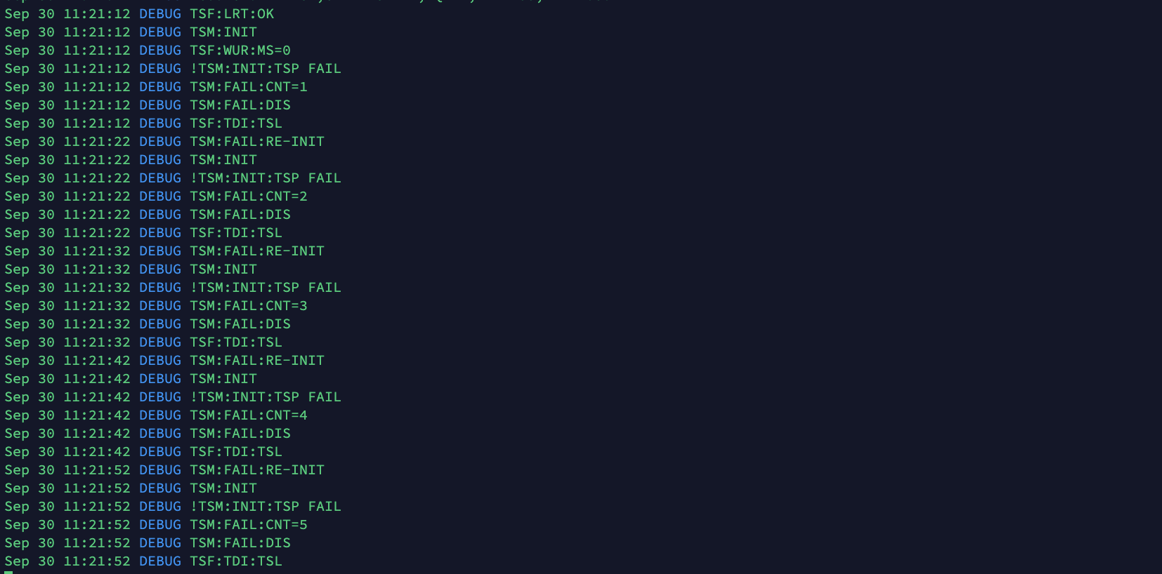
 Which give : [image: 1603047417867-6b45fd87-9d2b-4208-8d05-96cc591f18e2-image.png] We can see in sky blue, the sending of the state of a virtual "Motion" sensor from the Gateway to the Node (adjustable at the bottom of the interface). The other V_CUSTOMs are the RSSI of the RFM69 transmition stage. Oddity: after receiving the state of the Motion sensor, sent by the Gateway, the Node transmits a value of 127 ?? Everything works, out of the box, you just had to know how to start with the configuration of the RFM69HCW, thank you @scalz The second step is to replace the Win10 Controller with a Node-Red Controller. I already have a Node-Red server with its Dashboard running on an RPI 3B. I found "node-red-contrib-mysensors" but it still seems blurry to me (sorry I learn fast but you have to explain myself a long time) :yum: I think I'll open another Topic or continue on the original node-red-contrib-mysensors, Topic.
  • 0 Votes
    2 Posts
    40 Views
    mfalkviddM
    Looking at the debug log for the node and the gateway is probably the quickest path towards a solution.
  • OpenHAB + ESP8266 Ethernet GW without Radio: "send" does nothing

    6
    0 Votes
    6 Posts
    103 Views
    M
    @tssk What my issues with it are: there is an official binding and installation instruction here on mysensors.org and it does not work reliably the ESP8266 Ethernet Gateway Example connected the first time and then stopped working at all the ESP8266 MQTT Gateway Example connected the first time and then stopped working at all when looking at the MQTT broker, messages do come in, but the official binding (see above) does not register them, does not update the things/items in OpenHAB. This leads me to the conclusion that the official binding does not handle disconnects very well. Once disconnected, it either takes forever to re-establish a connection or it straight up refuses to work again unless maybe if I rebooted the OpenHAB machine. When I completely ignore the existence of the official OpenHAB binding that is promoted here as "the" way of connecting to OpenHAB, and instead use a generic MQTT binding, it works like a charm. I am just confused that the "official" way is so unreliable. I expected this to be the best way. That's why I went for it.
  • Unable to pair

    fpar fail esp8266 arduino uno
    4
    0 Votes
    4 Posts
    52 Views
    Tomáš MenglerT
    Ok, no help here.
  • 2 Votes
    2 Posts
    62 Views
    YveauxY
    @Frederic-Schaer said in Found my cause of gateway <-> RF24 connection issues (sign fail / NACK issues): Surprisingly, setting mysensors RF24 channel to 100, or even 123... did not help at all even if as I understand it, these should be outside of the wifi channels used in France (??) I found in the past that channels 100 and above are hardly usable with most nrf24 modules. Might be caused by bad antenna tuning, or fake chips, I'm not sure... Last thought : how is it possible that a consumer wifi AP (my neighbor's "FREEwifi" DSL box) is spanning over more than half the 2.4GHz spectrum ? isn't that extremely selfish ?? Yes, it seems to depend a lot on the hardware. I'm using ubiquity access points only nowadays which are very narrowbanded. Neighbouring access points delivered by internet hosters transmit a much broader spectrum. Worst of all seems to be my kids' Nintendo switch console which distorts the complete 2.4 wifi spectrum... Here you see the output of a channel scanner I'm currently working on, over the course of some 5 days: [image: 1602439909780-b91330dc-4350-4024-be3b-8192fee96c61-image.png] The vertical axis is nRF24 channels. My AP close to the scanner occupies channels 55..68, while e.g. there's also the much broader signal at channels 23..50. From channel 85 and above it's relatively quiet.
  • Problems with new GW

    3
    0 Votes
    3 Posts
    48 Views
    M
    Thanks, at least one of the nodes started working! Will try to update another one today.
  • ethernet gateway tsp fail

    6
    2
    0 Votes
    6 Posts
    78 Views
    mfalkviddM
    https://www.mysensors.org/about/overview tried to describe how MySensors works. A MySensors gateway can run on ta Raspberry Pi, or on a Wemos (or a number of other hardware). A MySensors gateway can communicate with a controller using a (virtual) usb port, wifi, wired internet, cellular internet, etc. For your wifi connection, you can use a wemos gateway if you like. In that case, there is no need to connect a nrf24 radio to the wemos. For "radio waves" you can build a MySensors node with nrf24 if you like. If you do that, you will need a gateway that also has a nrf24 radio.
  • BME280 433Mhz ESP2866

    2
    0 Votes
    2 Posts
    33 Views
    mfalkviddM
    Hi @Kevin-Roberts, welcome to the MySensors forum rtl_433 does not support the MySensors protocol.
  • MYSBoatloader burning confusion

    1
    0 Votes
    1 Posts
    28 Views
    No one has replied
  • [SOLVED] Node receives relais activation even without active controler

    3
    0 Votes
    3 Posts
    31 Views
    T
    Solved the re-connection problem by giving the MQTT broker a different and seperate IP-address, it was running on unraid´s main IP-address. Now testing for repeating relay activation, keeping fingers crossed. @Yveaux thx for your help.
  • Combine 2 different payload into function

    1
    1
    0 Votes
    1 Posts
    25 Views
    No one has replied
  • Raspberry pi and RFM69HCW

    1
    0 Votes
    1 Posts
    31 Views
    No one has replied

19

Online

11.7k

Users

11.2k

Topics

113.1k

Posts