Simple irrigation controller

-
Description
This project born from a necessity of water my domestic vegetable garden. Lettuces needs water all day and many times I forgot or don’t have time. There are other projects for irrigation but I have special requirements, it’s just one valve and valves that are sold in my country are AC24V for commercial controllers.
So I build a controller to add to my existing Mysensors/Domoticz network that can handle an AC24V with 12V to 3V volt DC . +/-3 Volts it’s how power this AC24V volts solenoids because AC24V transformers are difficult to find and expensive for what they are(ferromagnetic). And once solenoids(coils) warms up a lot especially with DC,with 3 volt they run cold and its the minimum that my valve requires to stay open.How it works?
Watering can be set on Arduino, 2 times per day ,morning and at evening. Or even once per day.
Or can be added timers on gateway (my case Domoticz) and everything stays remotely. Personally I prefer have it hard coded on Arduino in case of transmission fail.
I add a switch (one per valve) to turn it on every time I want and it automatically shuts down on timer that it’s set on code ,in “VALVE_TIME”. 1 hour by default.
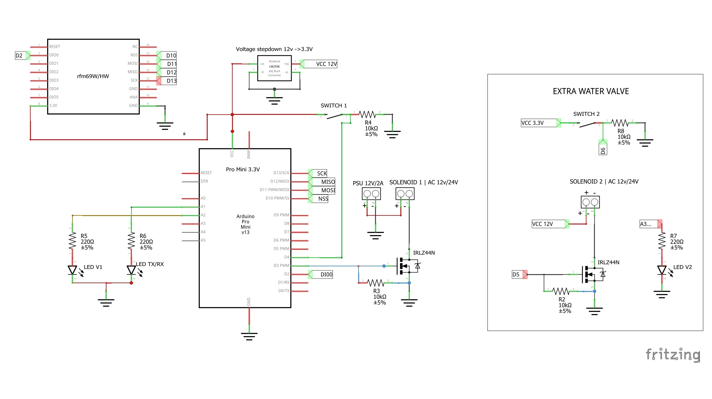
So there this timeout work in any of the timers(switch,gateway or internal timer).On code ,I set to “225”(100% or DC12v) on mosfet (IRLZ44N) during 400ms to kick the solenoid to open and then is set to “90” the rest of time to have around 3V on valve terminals. The entire project it’s powered with a standard electronic DC12V/2A transformer that powers the Arduino and the water valve.
There are 2 leds. One "Valve Power On" and other is TX/RX,note that blink time was slowed down for better understand when is communicating or its just retrying in loop and can't reach the gateway (for example). I have really good result with RFM69H(868mhz) communications. My garden its 40m/50m of my house or GW an never realize that were lost communications.
What I used:
Arduino (any 328P), I used pro mini 3.3v because the RFM69
RFM69H
LM2596 Voltage step down 12v→3.3V (or equivalent)
IRLZ44N or any logic level mosfet that work on 3.3V(one per valve that you use)
x2 leds
x2 screw terminal (2 wires)
Push Switch (Normally open)
Resistors x2 - 10K and x2 – 220ohm
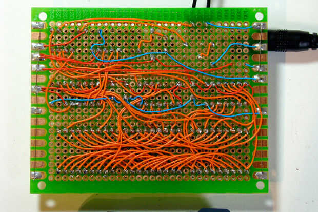
Protoboard (that green ones from ebay are awesome)
wire…Some thoughts : On my prototypes, I rarely make a dedicated pcb, I use thin ,wire to bridge components on protoboards. They are easy to build and easy to repair or remake in case of some issue. Never had an unexpected shot-circuit. And when my board are outdoor ,I use nail polish or transparent spray paint to cover the entire board. that makes an water prof board. And believe me even ip67 outdoor cases sometimes let water get in.
This is an example of wiring , of course in this our project we have many less wires :exampleSchematic
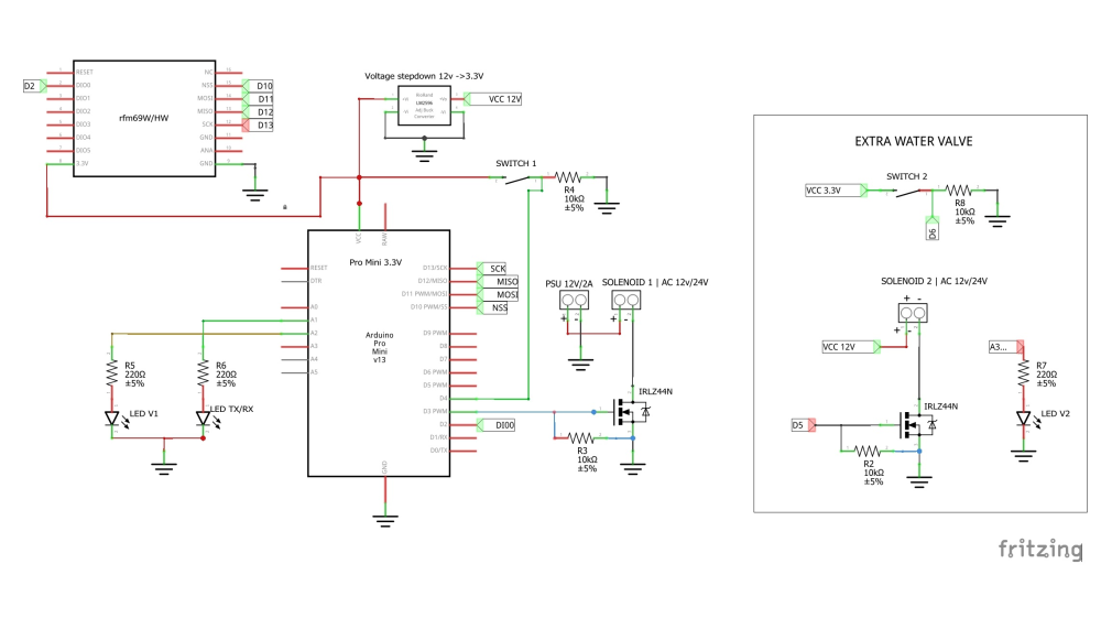
Note: each extra valve(Zone) needs an extra led, switch and mosfet.
Don’t let your garden dry! :)
Code
// Set blinking period (in milliseconds)
#define MY_DEFAULT_LED_BLINK_PERIOD 500
#define MY_WITH_LEDS_BLINKING_INVERSE
//#define MY_DEFAULT_ERR_LED_PIN 17
#define MY_DEFAULT_TX_LED_PIN 17
#define MY_DEFAULT_RX_LED_PIN 17

//#define MY_DEBUG
#define MY_RADIO_RFM69
//#define MY_REPEATER_FEATURE

#include <TimeLib.h>
#include <SPI.h>
#include <OneWire.h>
#include <DallasTemperature.h>
#include <MySensors.h>


#define ONE_WIRE_BUS 6
OneWire oneWire(ONE_WIRE_BUS);
DallasTemperature sensors(&oneWire);
//#define CHILD_ID_MOISTURE 4
#define CHILD_ID_TEMP 21
#define CHILD_ID_VALV1 10
//#define CHILD_ID_VALV2 11


#define RELAY_PIN  3  // Arduino Digital I/O pin number for relay  VALV 1
#define RELAY_PIN2  5  // Arduino Digital I/O pin number for relay VALV 2
#define BUTTON_PIN  4  // Arduino Digital I/O pin number for button
#define LEDR1   16  // LED A2 pin
#define LEDR2  15// LED A1 pin
//#define LEDERRO 17  // LED A3  pin


#define VALVE_TIME 3600000UL    //selenoid 1 goes off after () time  (7200000UL)-2HOUR
#define readtime 1800000UL  //time between read TEMPERATURE (3600000UL) - 1HOUR

//xxxxxxxxxxxxxxxxxxxxxxxxxxxxx |SET TIME HERE|     - valve1-  xxxxxxxxxxxxxxxxxxxxxxxx |
//TIME1
const int H1 = 17; //HOURS START PROGRAM     //time to start  selenoid1                 |
const int M1 = 00; //MINUTES START PROGRAM                                              |
//TIME2
const int H2 = 8; //HOURS START PROGRAM     //time to start  selenoid1                 |
const int M2 = 00; //MINUTES START PROGRAM
//----------------------------------------valve2--------------------------------------- |

unsigned long startMillis = 0;
unsigned long startMillisA = 0;

int reading;// the current reading from the input pin
bool RH = false;
int previous = LOW;
int timer = false;
bool timeReceived = false;
unsigned long  lastRequest = 0;

MyMessage msg1(CHILD_ID_TEMP, V_TEMP);
MyMessage msg2(CHILD_ID_VALV1, V_LIGHT);

bool state;


void before()
{
  // Startup up the OneWire library
  sensors.begin();  //DS18B20 LIBRARY START
}

void setup()
{
  //request time from gw
  requestTime(receiveTime);

  // Setup the button
  pinMode(BUTTON_PIN, INPUT);
  pinMode(RELAY_PIN, OUTPUT);
  pinMode(RELAY_PIN2, OUTPUT);

  pinMode(LEDR1, OUTPUT);
  pinMode(LEDR2, OUTPUT);
  sensors.begin();  //DS18B20 LIBRARY START


  // Make sure relays are off when starting up
  digitalWrite(RELAY_PIN, LOW);

}


void presentation()
{
  sendSketchInfo("irrigation_temp_soilMoisture", "2.0");
  present(CHILD_ID_TEMP, S_TEMP);
  present(CHILD_ID_VALV1, S_LIGHT);
}
void receiveTime(unsigned long time)
{
  // Ok, set incoming time
  setTime(time);
  timeReceived = true;

  Serial.print("Time now is: ");

  Serial.print(hour());
  Serial.print(":");
  Serial.print(minute());
  Serial.print(":");
  Serial.print(second());
}
//#################################################################################################
void VALV1_ON()
{
  analogWrite(RELAY_PIN, 255);
  delay(400);
  analogWrite(RELAY_PIN, 90);
  digitalWrite(LEDR1, HIGH);
  send(msg2.set(true), false);

}

void VALV1_OFF()
{
  analogWrite(RELAY_PIN, LOW);
  digitalWrite(LEDR1, LOW);
  send(msg2.set(false), false);
}
//#########################################################################################################3
// ✓ ORDER RECEIVED FROM GW  #

void receive(const MyMessage &message) {
  // We only expect one type of message from controller. But we better check anyway.
  if (message.isAck()) {
    // Serial.println("This is an ack from gateway");
  }

  if (message.type == V_LIGHT) {
    // Change relay state
    state = message.getBool();

    if (state == 1)
    {
      VALV1_ON();
    }

    else if (state == 0)
    {
      VALV1_OFF();
    }

  }
}
void loop()                 //loop
{


  unsigned long nows = millis();
  // If no time has been received yet, request it every 10 second from controller
  // When time has been received, request update every 12h
  if ((!timeReceived && (nows - lastRequest) > (10UL * 1000UL))
      || (timeReceived && (nows - lastRequest) > (43200000UL)))
  {
    // Request time from controller.
    //   Serial.println("requesting time");
    requestTime(receiveTime);
    lastRequest = nows;
  }


  //toogle  switch----------selenoid 1-------------------------------

  reading = digitalRead(BUTTON_PIN);


  if (reading == HIGH && RH == false)
  {
    VALV1_ON();
    RH = true;
    timer = true;
    delay(400);
  }
  else if (reading == HIGH && RH == true)
  {
    VALV1_OFF();
    RH = false;
    timer = false;
    delay(400);
  }

  // ✓ time out
  unsigned long nowMillis = millis();

  if ((timer == true) && (nowMillis - startMillis >= VALVE_TIME))
  {
    startMillis =  nowMillis ;
    VALV1_OFF();
    timer = false;

  }

  //✓ ON by time
  if ((hour() == H1 && minute() == M1) || (hour() == H2 && minute() == M2)  )
  {
    VALV1_ON();
    timer = true;
  }


  //✓ time to send temperature ?
  float temperature = sensors.getTempCByIndex(0);

  unsigned long nowMillisA = millis();
  if (nowMillisA - startMillisA >= readtime)
  {
    //✓ read temperature  sensors
    sensors.requestTemperatures();
    send(msg1.set(temperature, 1)); //send  temp to gw
    startMillisA =  nowMillisA ;  //reset time
  }
}
Todays Domoticz log from this sensors:
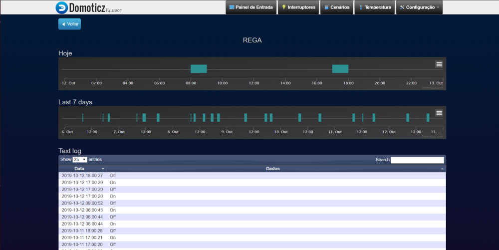
-
hey @Tmaster
are you still using this solution?
have you made any improvements or come across any issues with using it over time?@markjgabb said in Simple irrigation controller:
hey @Tmaster
are you still using this solution?
have you made any improvements or come across any issues with using it over time?Hello.still working good exept on winter that was disabled.
Last summer worked until october without any fail.
Hello! It looks like you're interested in this conversation, but you don't have an account yet.
Getting fed up of having to scroll through the same posts each visit? When you register for an account, you'll always come back to exactly where you were before, and choose to be notified of new replies (either via email, or push notification). You'll also be able to save bookmarks and upvote posts to show your appreciation to other community members.
With your input, this post could be even better 💗
Register Login