
E01-2G4M13S (NRF24L01+ PA + LNA)
-
I've ordered 10 E01-2G4M13S modules that should arrive mid December. Meanwhile, I want to submit gerber for pcbs that will use the module.
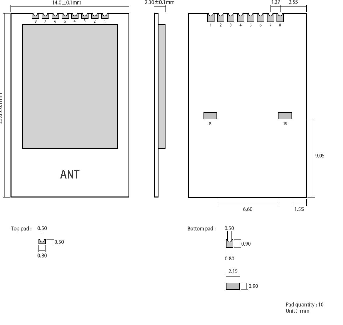
I'm a bit confused about the gnd connections. The pin definition table seems to contradict what's shown in a picture of the module
From the E01-2g4M13s manual:
Here's what the "not shield side" of the module looks like (from the EByte website):
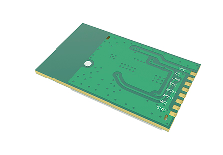
There's no documentation for a footprint.
I'd planned to hand solder the castellated edge of the module onto the pcb. If necessary, I could include pads on my pcb, apply solder paste, and reflow on a hot plate to connect pins 9 and 10 before doing the hand solder operation.
That might be tricky--the module may skew during the reflow.
I'd include pads in the pcb design so I'd be "cleared for the option", but the picture doesn't show any pads--just two plated holes where the shield probably attaches (solders).
Anybody use these modules and can say whether pins 9 and 10 need to be connected? Or, if the picture is just wrong?
(I sent email to the EByte support team, but no reply after a couple of days).
Thanks!
Hello! It looks like you're interested in this conversation, but you don't have an account yet.
Getting fed up of having to scroll through the same posts each visit? When you register for an account, you'll always come back to exactly where you were before, and choose to be notified of new replies (either via email, or push notification). You'll also be able to save bookmarks and upvote posts to show your appreciation to other community members.
With your input, this post could be even better 💗
Register Login