Raspberry GPIO NRF24l01+ make error


  • I'm trying to install the NRF24l01+ to my gpio pins from the raspberry with https://github.com/mysensors/Raspberry

    But when i run 'make' i get this error:

    root@pimatic:/home/pi/Raspberry# make
    g++ -o PiGateway MyGateway.o MySensor.o MyMessage.o PiEEPROM.o PiGateway.o -Wall -Ofast -mfpu=vfp -lpthread -g -D__Raspberry_Pi -mfloat-abi=hard -march=armv6zk -mtune=arm1176jzf-s -I. -Ilibrf24-bcm/ -lrf24-bcm
    /usr/bin/ld: cannot find -lrf24-bcm
    collect2: ld returned 1 exit status


  • @Wiebe-Nieuwenhuis said:

    -lrf24-bcm

    install the -lrf24-bcm library first and den run make here... u have a dir for lrf24 bcm install it before and u should not have this erro


  • Thanks, working now. With PiGateway i can run the gateway, is there a wat to daemonize it and start at boot?


  • Could you please share where you found the information how to connect the Radio to your Raspberry ?
    I am trying to get this to work for several day's but I am lost in all the different Information / Libraries and usage of different SPI ? GPIO pins.

    If you could give me a pointer it would be highly appreciated.


  • @sj44k -> https://github.com/mysensors/Raspberry

    Download that. First compile the librf24-bcm folder. Then compile the Raspberry one.

    From https://github.com/mysensors/Raspberry/tree/master/librf24-bcm

    PIN	NRF24L01	RPI	RPi -P1 Connector
    1	  GND			rpi-gnd	(25)
    2	  VCC			rpi-3v3	(17)
    3	  CE			rpi-gpio22	(15)
    4	  CSN			rpi-gpio8	(24)
    5	  SCK			rpi-sckl	(23)
    6	  MOSI			rpi-mosi	(19)
    7  	  MISO			rpi-miso	(21)
    8  	  IRQ			-Not connected


    The numbering for rpi is:

    1 2
    3 4
    5 6
    7 8
    9 10
    etc
    

    Don`t forget to enable the SPI from the raspbian config.

    To test your connection, simply open your program ./PiGatewaySerial
    It should print you something like this:

    root@raspberrypi:/home/pi/Raspberry# ./PiGatewaySerial
    Starting PiGatewaySerial...
    Protocol version - 1.4
    Created PTY '/dev/pts/3'
    Gateway tty: /dev/ttyMySensorsGateway
    ================ SPI Configuration ================
    CSN Pin          = CE0 (PI Hardware Driven)
    CE Pin           = Custom GPIO25
    Clock Speed      = 8 Mhz
    ================ NRF Configuration ================
    STATUS           = 0x0e RX_DR=0 TX_DS=0 MAX_RT=0 RX_P_NO=7 TX_FULL=0
    RX_ADDR_P0-1     = 0xe7e7e7e7e7 0xc2c2c2c2c2
    RX_ADDR_P2-5     = 0xff 0xc4 0xc5 0xc6
    TX_ADDR          = 0xe7e7e7e7e7
    RX_PW_P0-6       = 0x00 0x00 0x20 0x00 0x00 0x00
    EN_AA            = 0x3b
    EN_RXADDR        = 0x07
    RF_CH            = 0x10
    RF_SETUP         = 0x23
    CONFIG           = 0x0e
    DYNPD/FEATURE    = 0x3f 0x06
    Data Rate        = 250KBPS
    Model            = nRF24L01+
    CRC Length       = 16 bits
    PA Power         = PA_LOW


  • Thank you ! Will try this tonight, what kind of input could I expect when I do a test on my Aruino ? I have a Arduino Mega as a test board at this moment.
    Would a " Cat /dev/ttyMySensorsGateway' give me the output the Arduino is sending ?
    Arduino is set up as the mysensor temperature sensor as published on the website and seems to be working (according to the serial monitor).

    SPI is enabled, but for the sake of being sure I will start with a new and fresh Raspbian installation on the PI tonight SPI enabled.

    Again thanks for your reply ! I will post my findings.


  • You have to setup your arduino with a static node id. Something like

    gw.begin(incomingMessage, 10, false);
    or
    gw.begin(null, 10, false);
    or
    gw.begin(null, 10);
    

    10 is the node id.
    From my knowledge the raspi lib for nrf does not support the automatic node id. (or is just pimatic)
    Anyways, I don't use sensors. I just command the Arduino from raspi and my way of verifying the connection is the serial monitor linked to the arduino node. If it's found by the raspi and if he found the raspi the end of each line will be

    st=ok;
    

    If you get

    st=fail;
    

    You either did not set up the right node id or you need a capacitor on the nrf.
    Before you test the lib you can test the link with a serial arduino gateway and see what is going on.


  • Ok Radio was allready connected correctly, and I have the 4u7 capicitors installed.

    So this is what I understood from your tips am I correct ?

     git clone https://github.com/mysensors/Raspberry
    
    
    cd Rasberry
    make
    cd librf24-bcm
    make 
    make install
    cd ..
    ./PiGatewaySerial
    
    Starting PiGatewaySerial...
    Protocol version - 1.4
    Created PTY '/dev/pts/1'
    Gateway tty: /dev/ttyMySensorsGateway
    ================ SPI Configuration ================
    CSN Pin          = CE0 (PI Hardware Driven)
    CE Pin           = Custom GPIO25
    Clock Speed      = 8 Mhz
    ================ NRF Configuration ================
    STATUS           = 0x0e RX_DR=0 TX_DS=0 MAX_RT=0 RX_P_NO=7 TX_FULL=0
    RX_ADDR_P0-1     = 0xe7e7e7e7e7 0xc2c2c2c2c2
    RX_ADDR_P2-5     = 0xff 0xc4 0xc5 0xc6
    TX_ADDR          = 0xe7e7e7e7e7
    RX_PW_P0-6       = 0x00 0x00 0x20 0x00 0x00 0x00
    EN_AA            = 0x3b
    EN_RXADDR        = 0x07
    RF_CH            = 0x4c
    RF_SETUP         = 0x23
    CONFIG           = 0x0e
    DYNPD/FEATURE    = 0x3f 0x06
    Data Rate        = 250KBPS
    Model            = nRF24L01+
    CRC Length       = 16 bits
    PA Power         = PA_LOW
    

    So now I want to receive my Sensor info from my Arduino on my Raspbery.
    I am using this build with a small addition on it as I am using an Arduino Mega so the pins are different :

    http://www.mysensors.org/build/temp

    I Changed :

    MySensor gw;
    

    into

    MySensor gw(48,49)
    

    No I will do the figuring out about the node ID as I the tip about the auto ID does not work makes sense, the sensor now uses 0 and if I am correct that is the id of the gateway.

    By the way to even get that part done I needed to clear the EEProm of the Arduino (found it somewhere on some forum πŸ™‚ )

    I got the node secret also done now
    I needed to set πŸ‘

    `gw.begin(NULL,10,false,11);
    

    But still no communication / output on the Raspberry

    Output on de Arduino is :

    sensor started, id 10
    send: 10-10-11-0 s=255,c=0,t=17,pt=0,l=5,st=fail:1.4.1
    send: 10-10-11-0 s=255,c=3,t=6,pt=1,l=1,st=fail:11
    send: 10-10-11-0 s=255,c=3,t=11,pt=0,l=18,st=fail:Temperature Sensor
    send: 10-10-11-0 s=255,c=3,t=12,pt=0,l=3,st=fail:1.0
    send: 10-10-11-0 s=0,c=0,t=6,pt=0,l=5,st=fail:1.4.1
    send: 10-10-11-0 s=0,c=1,t=0,pt=7,l=5,st=fail:68.7```


  • @sj44k
    Tell me where did you connected the CE Pin on rPi..
    Do you have another Arduino so you can burn a serial gateway into it? So we can be sure that your Mega is sending and receiving properly?
    From your Arduino output he clearly does not link with the nrf on the Raspberry.


  • Checked the wires 5 times .. all looks well. CE is on pin 15
    Arduino should also be ok, I get error messages (Check wires) when it's connected differently

    (Heres the Arduino mega pinout as I used it
    http://forum.mysensors.org/topic/249/arduino-mega-sensor-shield-2/2 )

    I have an Uno ordered but at this moment I am stuck to 1 arduino
    I do have an extra Pi which I could use ..

    By the way, where would I receive the information on my pi in this example (in case it would work)
    ?
    in the screen where I started the
    ./PiGatewaySerial

    Or in a cat /dev/pts/1 ?


  • Move the pin on 22. The actual 22 pin not gpio22. Full restart the pi.

    I think you can cat the /dev/ttyMySensorsGateway. In the way I use it(with pimatic) all the commands are logged.


  • Tried that too, not working. But I now see why you asked that my output when starting PiGatewaySerial shows :
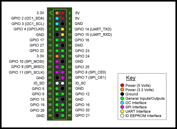
    CE Pin           = Custom GPIO25
    

    So that needs to be harware pin 22

    This picture helped a lot and makes now that I am 100% sure my Rpi is hooked up correctly.

    GPIO B+.jpg

    :s: must be overseeing something realy simple / stupid .. :/s:

    Guess it must be the Arduino Mega causing the issue, back to my drawingboard .. will keep you posted

    [edit]

    Just found an interesting SPI reference picture for my Arduino Mega
    Mega2560_R3_Label-small-v2 (2).png

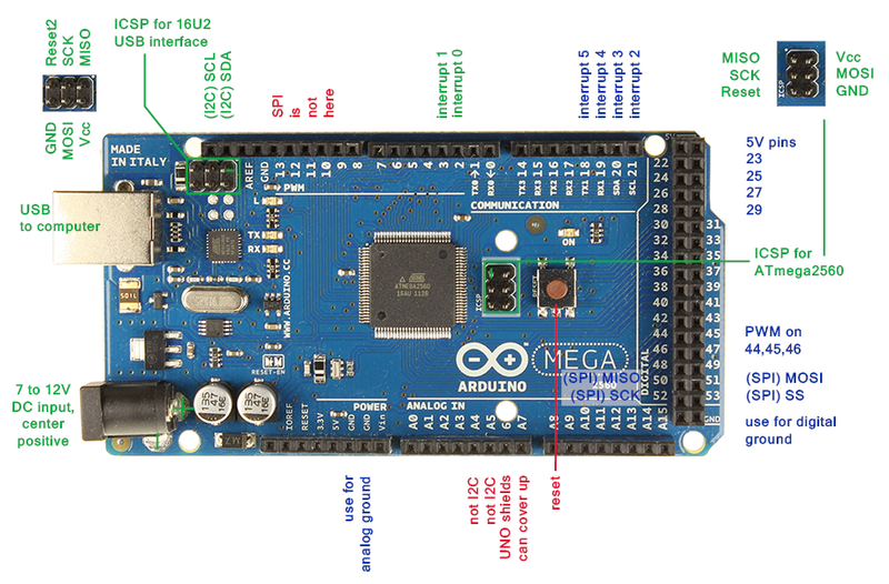
    My Pinout seems to be ok on the SPI side, just need to check CE / SE in regard to the scketch/libraries I am using.

    Radio 1 GND Paars Arduino GND
    Radio 2 3v3 Blauw Arduino 3,3v
    Radio 3 CE Groen Arduino 48
    Radio 4 CS Geel Arduino 49
    Radio 5 SCK Oranje Arduino 52
    Radio 6 MOSI Rood Arduino 51
    Radio 7 MISO Bruin Arduino 50


  • YEAH !
    It works !! thanks for pointing me in the right direction !
    Arduino needed the right scketch uploade (I messed so much with it I needed to go back which I just did)

    As a reference for all who are trying to get this to work.

    Use this pinout for the RPI B+
    Radio 1 grijs GND Rpi 25
    Radio 2 paars 3v3 Rpi 17
    Radio 3 blauw CE Rpi 22
    Radio 4 groen CS Rpi 24
    Radio 5 Geel SCK Rpi 23
    Radio 6 oranje MOSI Rpi 19
    Radio 7 Rood MISO Rpi 21

    Arduino Mega
    Radio 1 GND Paars Arduino GND
    Radio 2 3v3 Blauw Arduino 3,3v
    Radio 3 CE Groen Arduino 48
    Radio 4 CS Geel Arduino 49
    Radio 5 SCK Oranje Arduino 52
    Radio 6 MOSI Rood Arduino 51
    Radio 7 MISO Bruin Arduino 50

    I used the Libs mentioned in the post above by Vladut Grecu :
    https://github.com/mysensors/Raspberry

    I used this Temperature sketch :
    http://www.mysensors.org/build/temp

    Before I did got the Temp sketch operational I needed to clear my EEprom :
    http://arduino.cc/en/Tutorial/EEPROMClear

    /*
     * EEPROM Clear
     *
     * Sets all of the bytes of the EEPROM to 0.
     * This example code is in the public domain.
    
     */
    
    #include <EEPROM.h>
    
    void setup()
    {
      // write a 0 to all 512 bytes of the EEPROM
      for (int i = 0; i < 512; i++)
        EEPROM.write(i, 0);
       
      // turn the LED on when we're done
      digitalWrite(13, HIGH);
    }
    
    void loop()
    {
    }
    

    Than we need to edit the sketch a bit due to the fact that the Rpi gateway DOES NOT hand out the Node ID's automaticly, and the Sketch is not Arduino Mega compatible so :

    Set the Node ID manualy add

    gw.begin(NULL,10,false);
    

    Make sure the sketch is compatible with the Arduino MEGA pins (as published abover here)
    Change Line 12 in the sketch :

    MySensor gw;
    

    into

    MySensor gw(48,49)
    

    Than compile and hook everything up and upload the compiled sketch and start the Rpi (SPI enabled) and start
    ./PiGatewaySerial

    Output should show on your Pi when you
    Cat /dev/ttyMySensorsGateway

    Big Thank you to @Vladut-Grecu !


  • Admin

    Just received a great pull request for the Rapsberry created by @Holger-Meyers .

    https://github.com/mysensors/Raspberry


  • I had it finally working on my Pi2, but its very unstable. sometimes weird values, crashes and fails.

    switched to a usb serial arduino and that works great.


  • The original code on github is a bit buggy. Thats right. But the actual code after Holger has reworked it is running well.
    I am using it for nearly a month now. Nothing has crashed after Holger has looked after the reason why.

    Currently I am happy with the stability.


  • @Andreas-Maurer Could you tell me which controller you are using for your setup ?

    Thanks !


  • I am using fhem on the same PI. connected over the pseudo serial port.


  • What is the CPU usage of PiGatewaySerial when you look at top? Mine is using 97%.


  • It isnΒ΄t on the list πŸ™‚

    05-04-2015 09-00-21.jpg


  • Thanks.. Looked again today and it has calmed down.. Maybe it's just at start-up before there are any messages received or maybe something reading the Serial Port.


Log in to reply
 

Suggested Topics

  • 2
  • 75
  • 4
  • 482
  • 2
  • 6

0
Online

11.2k
Users

11.1k
Topics

112.5k
Posts