[Need help] Intercom project
-
Hello,
I don't know if this is the right place to ask for help for my project.
I live in an apartment building, so I have an intercom to open the door downstairs if someone rings my doorbell. I want to use mysensors to get a notification via domoticz on my phone trough pushover, and be able to open the door via domoticz.
I just started with mysensors, and I'm also new to the electrical stuff so hopefully I will learn how to this kind of stuff.
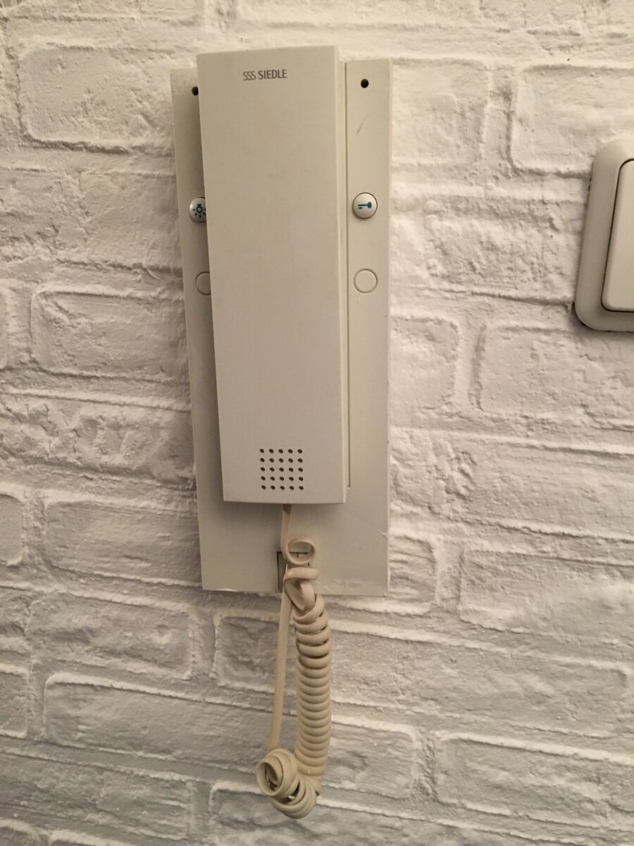
My intercom is a SSS Siedle, it has 2 wires going in a black one and a green one. one is probably for opening the door and the other for the voice.
I would really appreciate some help how to wire this up to an arduino, but still be able to use the horn and button on the intercom itself.
-
Looking at the pictures I only see the 2 wires. If the is no separate power line there must be some kind of protocol for the thing to communicate with the outside world. If you have a multimeter you can measure what happens with if the "bell rings". Probably the easiest to do: use a relay to bridgebridge the door open button and an optocoupler to over the ringer or measure the sound level.
If you can find a place to attach these the rest would be pretty standard. -
I'm guessing one of the four wires that go to the handset (RJ22) will carry the signal to 'ring' the speaker in the handset.
try your multimeter on each of those four and ground while the door button is pressed.
-
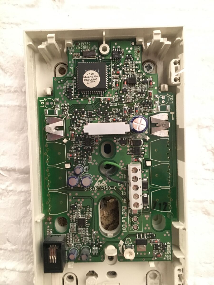
As this is the outside box, can you post pictures of the inside box controller, I think this is the key to get it on you vera box. I suspect the two buttons actually modulate a high frequency onto the two wires, as you still need to pass audio both ways and power to make it all work.
-
-
Yes, this is the inside box in my appartment, I think the green wire is for opening the door. When I get home I will try to solder a wire to the button and use a relay. That sould work I think, then I need to create a blocky in domoticz that when I push the virtual button inside domoticz it turns the relay off again.
@PandaNL It's unlikely that a single wire is used for the relay. Typically these systems work by superimposing different signals on the same two wires. The voice will be on that pair and so will the control signal to open the door. The control signal for the relay could be a dc voltage of a certain level or an ac signal at a specific frequency. There's equipment at the head end that will take this signal and operate the relay. It's unlikely that you are directly controlling the relay that opens the door. Hook up a multimeter across the pair and measure ac voltage and then dc voltage while you are making a voice call and opening the door. Start at 50v or so and work your way down to lower levels if you don't pick anything up.
Cheers
Al -
Hi Sparkman,
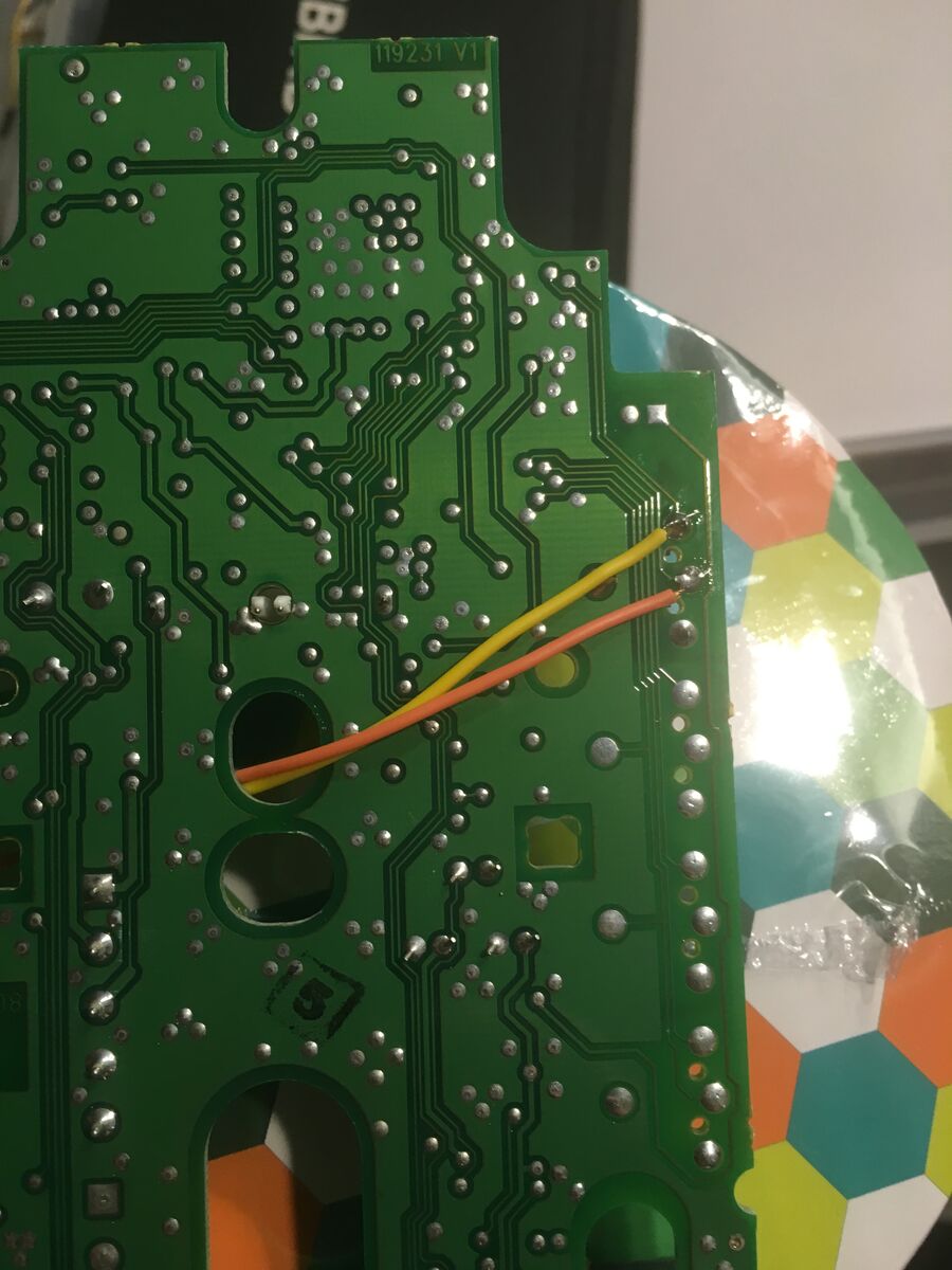
Used the multimeter and it gives a reading of 20v dc. when the button for the door is pushed two metal parts touch each other and will send a signal to open the door.
Soldered 2 wires to those connections and it seems to work with the relay, the only thing I need to figure out now is how to get a signal when someone rings.
-
Hi Sparkman,
Used the multimeter and it gives a reading of 20v dc. when the button for the door is pushed two metal parts touch each other and will send a signal to open the door.
Soldered 2 wires to those connections and it seems to work with the relay, the only thing I need to figure out now is how to get a signal when someone rings.
@PandaNL said:
Used the multimeter and it gives a reading of 20v dc. when the button for the door is pushed two metal parts touch each other and will send a signal to open the door.
Soldered 2 wires to those connections and it seems to work with the relay, the only thing I need to figure out now is how to get a signal when someone rings.
Good news. For the ring, it's likely a 60-90v ac signal, so use the multimeter to confirm that. There are pre-built ring detectors available, one example is made by Velleman, or you can build your own. Google "telephone ring detector circuit" and you should be able to find examples.
Cheers
Al -
Could I also use a ACS712 30A Module to see if there is a change in voltage with a script in domoticz?
-
The ACS712 should arive today, however I couldn't find the sketch to send over the voltage measurements, maybe I'm overlooking but which sketch can I use?
-
Can't seem to get a good readout from the module yet.
Tried the following code
/*
Measuring Current Using ACS712
*/
const int analogIn = A0;
int mVperAmp = 185; // use 100 for 20A Module and 66 for 30A Module
int RawValue= 0;
int ACSoffset = 2500;
double Voltage = 0;
double Amps = 0;

void setup(){
 Serial.begin(9600);
}

void loop(){

 RawValue = analogRead(analogIn);
 Voltage = (RawValue / 1023.0) * 5000; // Gets you mV
 Amps = ((Voltage - ACSoffset) / mVperAmp);


 Serial.print("Raw Value = " ); // shows pre-scaled value
 Serial.print(RawValue);
 Serial.print("\t mV = "); // shows the voltage measured
 Serial.print(Voltage,3); // the '3' after voltage allows you to display 3 digits after decimal point
 Serial.print("\t Amps = "); // shows the voltage measured
 Serial.println(Amps,3); // the '3' after voltage allows you to display 3 digits after decimal point
 delay(2500);

}```
It gives me the following readout, tried the multi meter on signal and also a lamp on ac. It shows these values even if nothing is connected. Connected the module to pin 0 on the arduino and provided it with 5v from the arduino.
Raw Value = 876 mV = 4281.525 Amps = 9.630
Raw Value = 877 mV = 4286.413 Amps = 9.656
Raw Value = 878 mV = 4291.300 Amps = 9.683
Raw Value = 877 mV = 4286.413 Amps = 9.656
Raw Value = 877 mV = 4286.413 Amps = 9.656
Raw Value = 875 mV = 4276.637 Amps = 9.603What would be the formula to just show Voltage?, when the door is ringed the voltage changes from 20v to 23~24v, when the button is pressed to open the door it drops to 17v.
-
This is the only place where I could find a picture of this exact model and I wanted to know what the left buttob does. It looks like a light or something but it doesn’t do anything. Also, how did you open it up? I couldn’t find any screws
Did you read the manual? if not read below...
In-house telephone light button Each in-house telephone has a light button to actuate a joint staircase or entrance light.
Hello! It looks like you're interested in this conversation, but you don't have an account yet.
Getting fed up of having to scroll through the same posts each visit? When you register for an account, you'll always come back to exactly where you were before, and choose to be notified of new replies (either via email, or push notification). You'll also be able to save bookmarks and upvote posts to show your appreciation to other community members.
With your input, this post could be even better 💗
Register Login