Which ATmega do i go with?
-
Go with 328p.. you'll only get more problems, if you choose other chips (like the attiny mcus)
328 is the standard for arduino. Just be sure that you have access to programming (ISP port) pins on the mcu, otherwise you'll have problems in putting in the bootloader.
-
You don't need the crystal, there is an internal 8mhz RC oscillator available.
I would recommend to take a look at the sensebender, it's as basic as it can be (just remove sensor / flash / atsha204 if you don't need those)
@tbowmo said:
You don't need the crystal, there is an internal 8mhz RC oscillator available.
I would recommend to take a look at the sensebender, it's as basic as it can be (just remove sensor / flash / atsha204 if you don't need those)
How do you programme a factory atmega328p to run on 8mhz internal?
-
Right, okay. So 328-PU it is. By the way just to let you know i was looking at the likes of the ATmega8, and others in the mega range. Wasn't bothering with the ATtiny range. But i'll stick with ATmega328-PU. But other than the chip, rf24, the switch and a serial connection for uploading the bootloader and sketch, i don't need anything else to have a functioning 'arduino', right?
Ill get some more design and schematic work done when i get home from work tonight and get some drafts up on here.
-
@tbowmo said:
You don't need the crystal, there is an internal 8mhz RC oscillator available.
I would recommend to take a look at the sensebender, it's as basic as it can be (just remove sensor / flash / atsha204 if you don't need those)
How do you programme a factory atmega328p to run on 8mhz internal?
@Mickey said:
@tbowmo said:
You don't need the crystal, there is an internal 8mhz RC oscillator available.
I would recommend to take a look at the sensebender, it's as basic as it can be (just remove sensor / flash / atsha204 if you don't need those)
How do you programme a factory atmega328p to run on 8mhz internal?
I have the line of code in my documents at home somewhere, ill post them later if no body provides anything by then. If i can find them that is.
-
By default the atmega328p is running from the internal 8Mhz oscillator, but with clkdiv8 enabled, so that it runs at 1Mhz. For running it at 8Mhz you have to set the fuses and disable the clkdiv8. I'm using the following avrdude command to set fuses with my jtagice3 programmer in an atmega328p
avrdude -c jtag3isp -p m328p\
-U lfuse:w:0xE2:m \
-U hfuse:w:0xD2:m \
-U efuse:w:0xFE:m \
-U lock:w:0xEF:m
change above to use the programmer that you have
@tbowmo said:
By default the atmega328p is running from the internal 8Mhz oscillator, but with clkdiv8 enabled, so that it runs at 1Mhz. For running it at 8Mhz you have to set the fuses and disable the clkdiv8. I'm using the following avrdude command to set fuses with my jtagice3 programmer in an atmega328p
avrdude -c jtag3isp -p m328p\
-U lfuse:w:0xE2:m \
-U hfuse:w:0xD2:m \
-U efuse:w:0xFE:m \
-U lock:w:0xEF:m
change above to use the programmer that you have
So if my current fuses are like this:
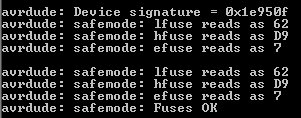
can I still communicate with the chip with usbasp without external crystal? -
Running higher frequency will use more current.. In theory keep your oscillator frequency as low as possible. Also you should have a look at how often you want to report the temperature. Normal temperature sketches are measuring once every minute (or even less frequently). Then it doesn't matter if it takes 1 mili second, or 2 mili seconds to perform an operation.
Also, what temperature sensor are you planning to use? If it's digital, your MCU is probably going to wait for the temperature conversion etc.. anyways, (which can be up to several mili seconds). So again, it doesn't matter if the MCU is running 8 or 16Mhz.
Another point, is that for running 16Mhz, you need to supply the atmega328p with 5V, as it's not rated for running 16Mhz at 3V (or lower). That means you need to have a "5V battery" (stepup or the like). in order to get it running at 5V.
Now for the external flash, and bootloader support. There are two bootloaders available for OTA FW upgrades.
- MysBootloader - no external flash needed, but only supports NRF24, and no security features (signing etc.)
- DualOptiboot - needs external flash to store fw while uploading it. Supporting both NRF24 and RFM69 radios, and supports signing (dev branch of Mysensors library is probably needed)
If you use MysBootloader, it doesn't loose firmware if it looses power. Firmware is still stored in internal flash on the MCU, but the node will not function normally while uploading a new sketch, as it's in bootloader mode. While using DualOptiboot / external flash, node will continue to work with the old sketch, untill the new sketch is uploaded to the node (external flash) and verified, after which the content of the external flash will be moved to internal MCU flash and executed.
@tbowmo said:
Now for the external flash, and bootloader support. There are two bootloaders available for OTA FW upgrades.
- MysBootloader - no external flash needed, but only supports NRF24, and no security features (signing etc.)
- DualOptiboot - needs external flash to store fw while uploading it. Supporting both NRF24 and RFM69 radios, and supports signing (dev branch of Mysensors library is probably needed)
Without using external flash could i use the Arduino bootloader? Did you only mention these 2 for their "OTA Firmware upgrade" ability? I'm struggling to workout how to burn this MysBootloader onto my chip. I can't find much information on this.
EDIT: So, I've been reading on the Google Docs for bootloading, and it would appear all that i have to do is put the MysBootloader sub-folder into the bootloaders folder in my Arduino IDE documents. So, i have done that but i still only have "Burn Bootloader" in the tools drop down menu, is this normal not to be able to choose which bootloader i would like to burn or do i need to have my board plugged into my computer to then be recognised to be able to burn MYSBootloader?
-
And which way is your/the preferred method of burning the bootloader, would you use a Arduino Uno and burn the bootloader using the "Arduino as ISP" option or would you go with something like a USBtinyISP adapter? Could you provide a link for a specific programmer if you use one as I'm seeing a lot of varying types/sizes/shapes and I'de like a recommendation of a working device from someone that uses one. If you use an Arduino UNO, i will just purchase one of those instead.
-
@tbowmo said:
Now for the external flash, and bootloader support. There are two bootloaders available for OTA FW upgrades.
- MysBootloader - no external flash needed, but only supports NRF24, and no security features (signing etc.)
- DualOptiboot - needs external flash to store fw while uploading it. Supporting both NRF24 and RFM69 radios, and supports signing (dev branch of Mysensors library is probably needed)
Without using external flash could i use the Arduino bootloader? Did you only mention these 2 for their "OTA Firmware upgrade" ability? I'm struggling to workout how to burn this MysBootloader onto my chip. I can't find much information on this.
EDIT: So, I've been reading on the Google Docs for bootloading, and it would appear all that i have to do is put the MysBootloader sub-folder into the bootloaders folder in my Arduino IDE documents. So, i have done that but i still only have "Burn Bootloader" in the tools drop down menu, is this normal not to be able to choose which bootloader i would like to burn or do i need to have my board plugged into my computer to then be recognised to be able to burn MYSBootloader?
@samuel235 Please follow these instructions for burning MYSBootloader and testing OTA updates with MYSController. Both, USBasp and ArudinoISP are easy to use as long as you do not mix up the cables...
-
@samuel235 Please follow these instructions for burning MYSBootloader and testing OTA updates with MYSController. Both, USBasp and ArudinoISP are easy to use as long as you do not mix up the cables...
@tekka - How on earth did i not stumble across this! Thank you very much! I will get ordering myself an UNO in preperation to getting my board manufactured. Now i know which connections are needed in my ISP header, i will carry on sketching out the schematic. Thank you once again!
-
I'm using genuine atmel programmers (currently I'm on jtagice3) been serving me fine for the last couple of years (also have the added benefits of being able to work together with gdb, so I can debug arduino code on my atmel sam D21 mcu)
Anyways, there are lot's of (cheaper) programmers out there, amongst others you could use another arduino as programmer..
Hello! It looks like you're interested in this conversation, but you don't have an account yet.
Getting fed up of having to scroll through the same posts each visit? When you register for an account, you'll always come back to exactly where you were before, and choose to be notified of new replies (either via email, or push notification). You'll also be able to save bookmarks and upvote posts to show your appreciation to other community members.
With your input, this post could be even better 💗
Register Login