sensors, voltage and pull up/down resistors
-
While designing and soldering up my first board with 3 sensors (terminals) I was thinking about making my next (5 volt) board as generic as possible.
For me that would mean:
- 2 3-pin terminals for sensors to digital (interrupt) pins
- no brainer
- 1 3-pin terminal for a sensor to analog pin
- no brainer
- pull up or pull down resistors
- I can either make space for 2 smd resistors and solder only one on the board
- Or be flexible and use a switch/jumper to switch between gnd/vcc per sensor
- 3.3 volt or 5 volt
- I was thinking of making the 2 digital sensors 3.3v and the analog one 5v
- Or be flexible and use a switch/jumper to switch between 3.3v/5v per sensor
I could also make the terminals all with pull up resistors and 3.3v and make a single board for the occasional exception (which will happen anyway since not all sensors are 3 pins)...
Obviously the board has to be as small as possible so when I use a switch/jumper they need to be small :)
Any thoughts about this?
How would you do it? -
While designing and soldering up my first board with 3 sensors (terminals) I was thinking about making my next (5 volt) board as generic as possible.
For me that would mean:
- 2 3-pin terminals for sensors to digital (interrupt) pins
- no brainer
- 1 3-pin terminal for a sensor to analog pin
- no brainer
- pull up or pull down resistors
- I can either make space for 2 smd resistors and solder only one on the board
- Or be flexible and use a switch/jumper to switch between gnd/vcc per sensor
- 3.3 volt or 5 volt
- I was thinking of making the 2 digital sensors 3.3v and the analog one 5v
- Or be flexible and use a switch/jumper to switch between 3.3v/5v per sensor
I could also make the terminals all with pull up resistors and 3.3v and make a single board for the occasional exception (which will happen anyway since not all sensors are 3 pins)...
Obviously the board has to be as small as possible so when I use a switch/jumper they need to be small :)
Any thoughts about this?
How would you do it?@marceltrapman Remember that pull-up resistors are only required in 'special' cases as the ATMega has internal pull-ups that can be enabled.
I guess your sensor boards will be put away somewhere after assembling, so flexibility by using jumpers will only take up board space and will not bring anything when sensor is in use.
I'd prefer to have double SMD resistor footprints with only one mounted.
Another option is to use solder jumpers, which are small but not as easy to toggle as regular jumpers: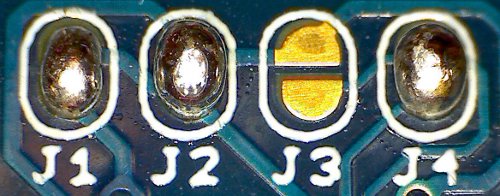
Or even something like:

Where one of the outer pads is VCC, and the other GND. By shorting the center to one of the two you select either VCC or GND.
Most Chinese off-the-shelf analog sensors are 5V supplied, so that seems to be a sane choice.
-
@marceltrapman Remember that pull-up resistors are only required in 'special' cases as the ATMega has internal pull-ups that can be enabled.
I guess your sensor boards will be put away somewhere after assembling, so flexibility by using jumpers will only take up board space and will not bring anything when sensor is in use.
I'd prefer to have double SMD resistor footprints with only one mounted.
Another option is to use solder jumpers, which are small but not as easy to toggle as regular jumpers:Or even something like:
Where one of the outer pads is VCC, and the other GND. By shorting the center to one of the two you select either VCC or GND.
Most Chinese off-the-shelf analog sensors are 5V supplied, so that seems to be a sane choice.
@Yveaux said:
I'd prefer to have double SMD resistor footprints with only one mounted.
Thank you for your fast reply!!!
That is what I have right now.
But I wanted to make sure that I did not overlook anything and ask 'the experts' :)About 5v, almost all sensors I have claim to be 5v but work with 3.3v as well so I am not certain about that. I guess the solder jumpers could do a good job here...
-
@Yveaux hello, a question also for me... I have some sensors without boards that require either 6V or 2.5V, what should I do on this ?
@epierre Ideally you could add some converters to get to 6V or 2.5V.
Another option is to test if the 6V sensors work allright at 5V; could just be the case...
2.5V you can easily create by adding a silicon diode in series with a 3.3V supply. The voltage drop over the diode lowers the supply voltage by approx. 0.7V giving around 2.6V. -
There are 5V and 3.3v digital sensors as well as analog, so making it selectable would add flexibility.
Either with jumpers or by using 4 pin connectors with both voltages.
Hello! It looks like you're interested in this conversation, but you don't have an account yet.
Getting fed up of having to scroll through the same posts each visit? When you register for an account, you'll always come back to exactly where you were before, and choose to be notified of new replies (either via email, or push notification). You'll also be able to save bookmarks and upvote posts to show your appreciation to other community members.
With your input, this post could be even better 💗
Register Login