Can't see my nodes on HA web interface
-
Martin, I've added that line and now i can see the sensor as a switch on my HA web interface. The thing now is, when I trigger the switch from OFF to ON, the serial gateway sends the information to the node but the switch come back to OFF state. This is what i'm seeing on logs
NFO:mysensors.mysensors:n:0 c:0 t:3 s:9 p:gateway started, id=0, parent=0, distance=0
INFO:mysensors.mysensors:n:0 c:0 t:3 s:9 p:read: 19-19-0 s=255,c=3,t=15,pt=2,l=2,sg=0:0
INFO:mysensors.mysensors:n:0 c:0 t:3 s:9 p:read: 19-19-0 s=255,c=0,t=17,pt=0,l=5,sg=0:1.5.4
INFO:homeassistant.components.mysensors:No sketch_name: node 19
INFO:homeassistant.components.mysensors:No sketch_name: node 19
INFO:homeassistant.components.mysensors:No sketch_name: node 19
INFO:homeassistant.components.mysensors:No sketch_name: node 19
INFO:mysensors.mysensors:n:0 c:0 t:3 s:9 p:read: 19-19-0 s=255,c=3,t=6,pt=1,l=1,sg=0:0
INFO:mysensors.mysensors:n:0 c:0 t:3 s:9 p:send: 0-0-19-19 s=255,c=3,t=6,pt=0,l=1,sg=0,st=ok:M
INFO:mysensors.mysensors:n:0 c:0 t:3 s:9 p:read: 19-19-0 s=255,c=3,t=11,pt=0,l=12,sg=0:Relay Outlet
INFO:mysensors.mysensors:n:0 c:0 t:3 s:9 p:read: 19-19-0 s=255,c=3,t=12,pt=0,l=3,sg=0:1.0
INFO:mysensors.mysensors:n:0 c:0 t:3 s:9 p:read: 19-19-0 s=1,c=0,t=3,pt=0,l=0,sg=0:
INFO:mysensors.mysensors:n:0 c:0 t:3 s:9 p:read: 19-19-0 s=1,c=1,t=2,pt=2,l=2,sg=0:1
INFO:homeassistant.components.mysensors:Adding new devices: <Entity Relay Outlet 19 1: off>
INFO:homeassistant.core:Bus:Handling <Event state_changed[L]: old_state=None, new_state=<state switch.relay_outlet_19_1=unavailable; friendly_name=Relay Outlet 19 1 @ 2016-06-06T13:53:25.968979-03:00>, entity_id=switch.relay_outlet_19_1>
INFO:homeassistant.core:Bus:Handling <Event state_changed[L]: old_state=None, new_state=<state group.all_switches=unknown; auto=True, friendly_name=all switches, hidden=True, order=0, entity_id=[] @ 2016-06-06T13:53:25.981643-03:00>, entity_id=group.all_switches>
INFO:homeassistant.core:Bus:Handling <Event state_changed[L]: old_state=<state group.all_switches=unknown; auto=True, friendly_name=all switches, hidden=True, order=0, entity_id=[] @ 2016-06-06T13:53:25.981643-03:00>, new_state=None, entity_id=group.all_switches>
INFO:homeassistant.core:Bus:Handling <Event state_changed[L]: old_state=None, new_state=<state group.all_switches=unknown; auto=True, friendly_name=all switches, hidden=True, order=0, entity_id=('switch.relay_outlet_19_1',) @ 2016-06-06T13:53:26.018724-03:00>, entity_id=group.all_switches>
INFO:homeassistant.core:Bus:Handling <Event state_changed[L]: old_state=<state switch.relay_outlet_19_1=unavailable; friendly_name=Relay Outlet 19 1 @ 2016-06-06T13:53:25.968979-03:00>, new_state=<state switch.relay_outlet_19_1=on; V_STATUS=on, battery_level=0, child_id=1, device=/dev/ttyUSB0, friendly_name=Relay Outlet 19 1, node_id=19 @ 2016-06-06T13:53:26.042212-03:00>, entity_id=switch.relay_outlet_19_1>
INFO:homeassistant.core:Bus:Handling <Event state_changed[L]: old_state=<state group.all_switches=unknown; auto=True, friendly_name=all switches, hidden=True, order=0, entity_id=('switch.relay_outlet_19_1',) @ 2016-06-06T13:53:26.018724-03:00>, new_state=<state group.all_switches=on; auto=True, friendly_name=all switches, hidden=True, order=0, entity_id=('switch.relay_outlet_19_1',) @ 2016-06-06T13:53:26.070897-03:00>, entity_id=group.all_switches>
this is what i see when i press the switch from HA web interface
INFO:homeassistant.core:Bus:Handling <Event call_service[L]: domain=homeassistant, service_data=entity_id=switch.relay_outlet_19_1, service=turn_off, service_call_id=3055117168-3>
INFO:homeassistant.core:Bus:Handling <Event call_service[L]: domain=switch, service_data=entity_id=['switch.relay_outlet_19_1'], service=turn_off, service_call_id=3055117168-4>
INFO:homeassistant.core:Bus:Handling <Event service_executed[L]: service_call_id=3055117168-4>
INFO:homeassistant.core:Bus:Handling <Event service_executed[L]: service_call_id=3055117168-3>
INFO:homeassistant.components.http:"POST /api/services/homeassistant/turn_off HTTP/1.1" 200 -
INFO:mysensors.mysensors:n:0 c:0 t:3 s:9 p:send: 0-0-19-19 s=1,c=1,t=2,pt=0,l=1,sg=0,st=ok:0
Thanks!
-
Yes, @Dave-Dan is correct. Look at the example sketch, in the end, you'll see that the node sends confirmation of the updated state back to the gateway and controller.
-
I've got an updated relay+button script at home that fixes this issue. I'll post it after work for anyone else who may need it.
@drock1985, please can you share it?
Thank you.
Antoni. -
@drock1985, please can you share it?
Thank you.
Antoni. -
Guys, I'm adding this info to the thread just in case that someone may get this useful.
This is my final sketch:
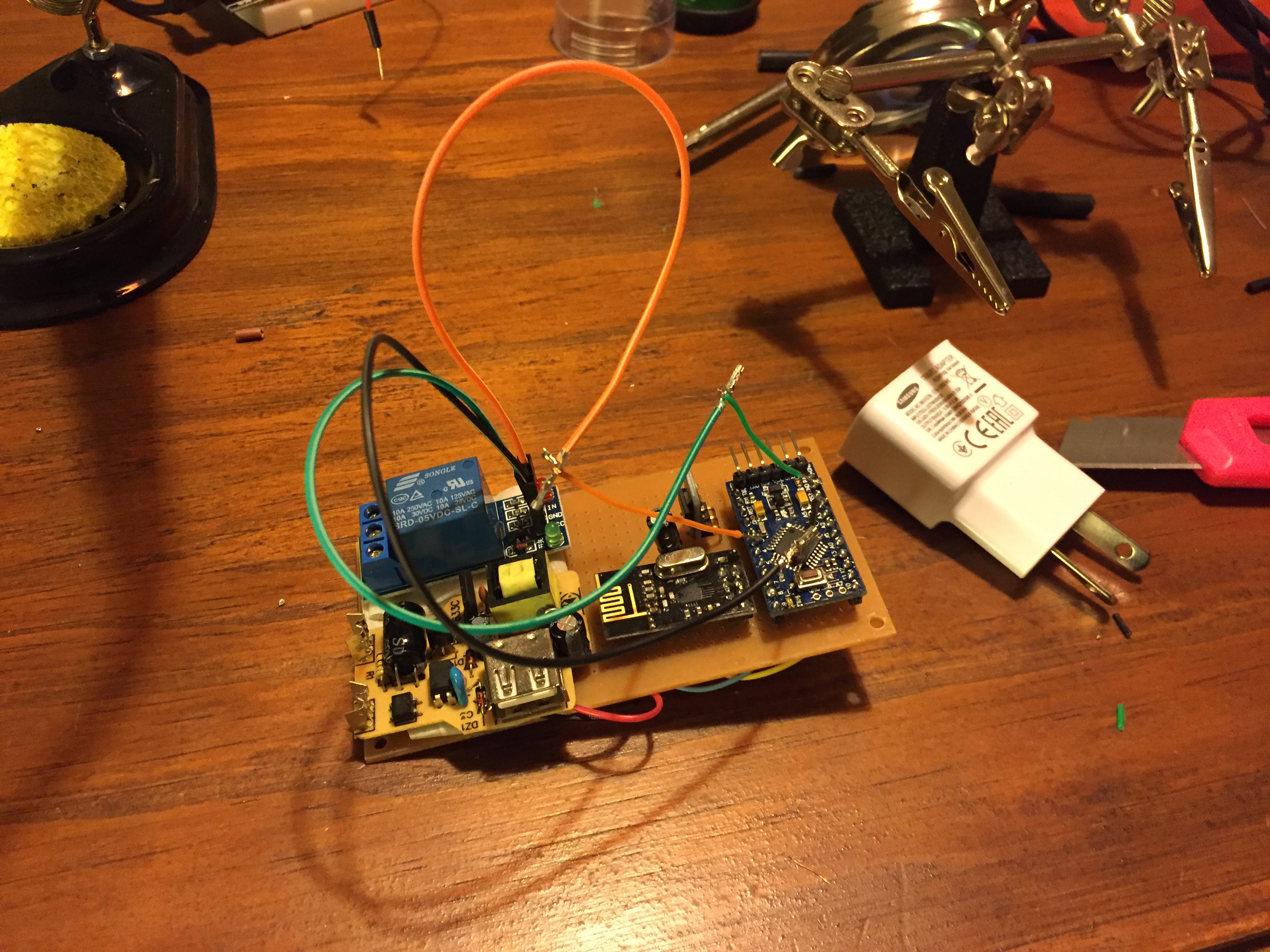
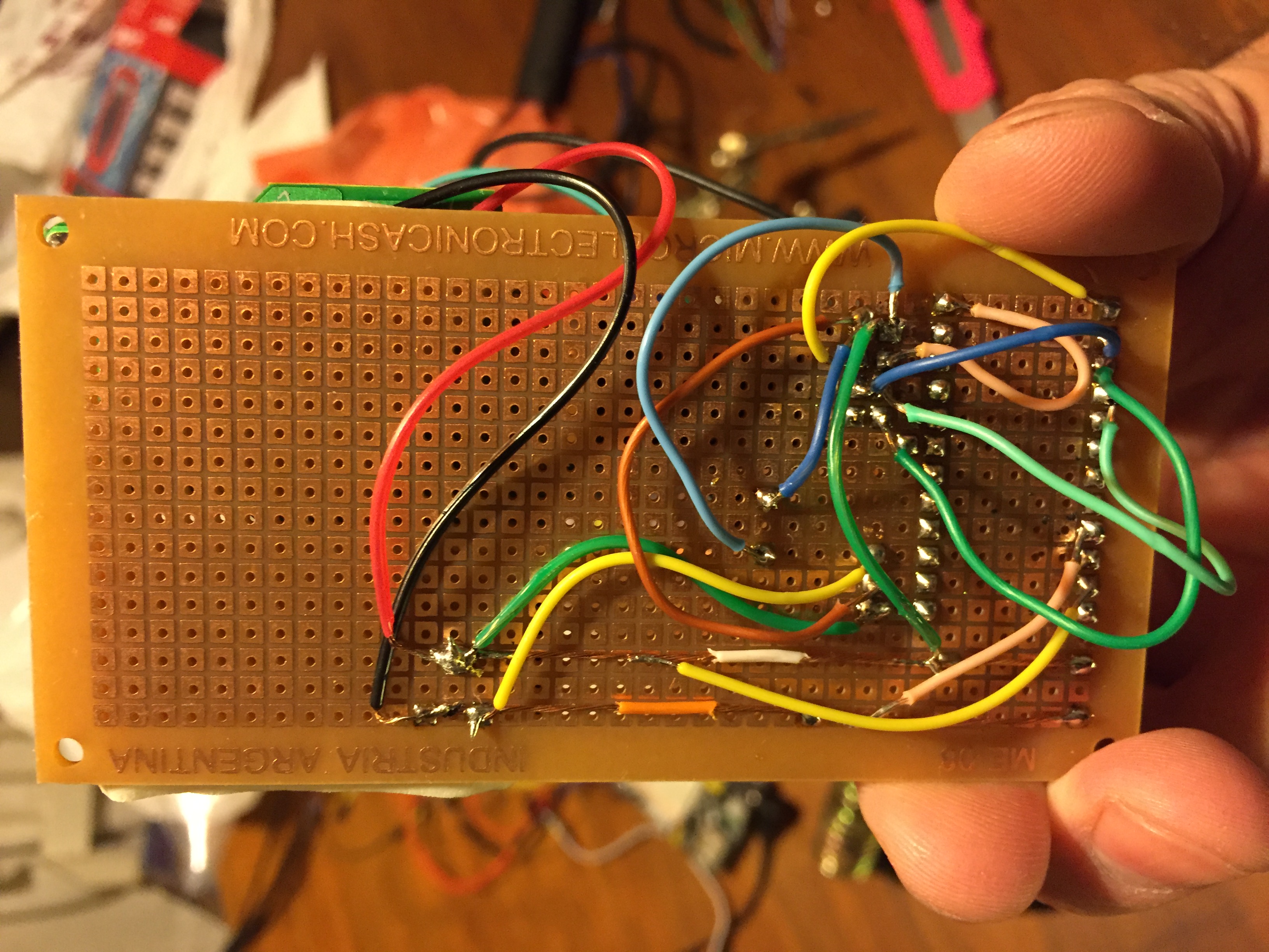
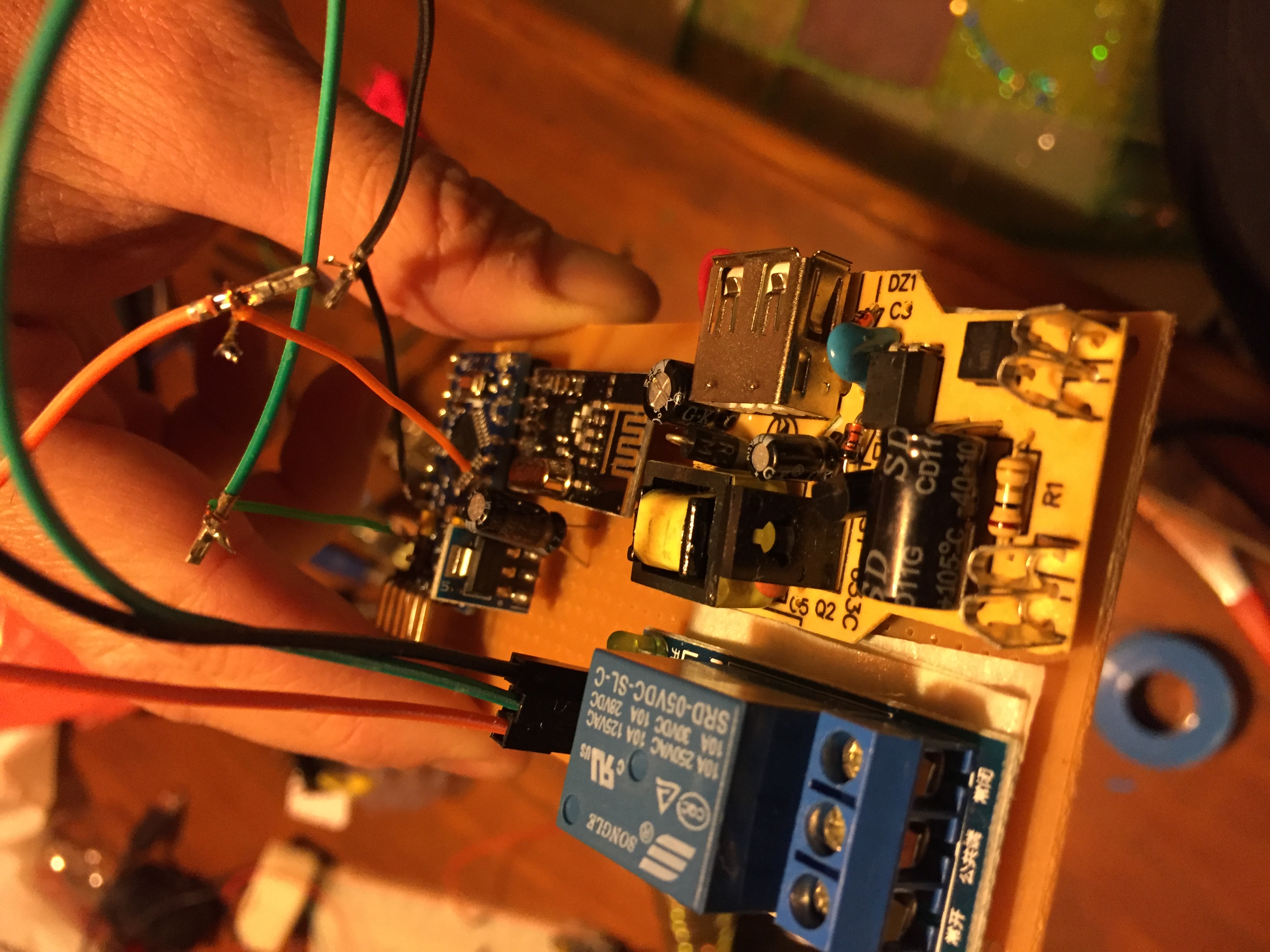
/**
 * The MySensors Arduino library handles the wireless radio link and protocol
 * between your home built sensors/actuators and HA controller of choice.
 * The sensors forms a self healing radio network with optional repeaters. Each
 * repeater and gateway builds a routing tables in EEPROM which keeps track of the
 * network topology allowing messages to be routed to nodes.
 *
 * Created by Henrik Ekblad <henrik.ekblad@mysensors.org>
 * Copyright (C) 2013-2015 Sensnology AB
 * Full contributor list: https://github.com/mysensors/Arduino/graphs/contributors
 *
 * Documentation: http://www.mysensors.org
 * Support Forum: http://forum.mysensors.org
 *
 * This program is free software; you can redistribute it and/or
 * modify it under the terms of the GNU General Public License
 * version 2 as published by the Free Software Foundation.
 *
 *******************************
 *
 * REVISION HISTORY
 * Version 1.0 - Henrik Ekblad
 *
 * DESCRIPTION
 * Example sketch showing how to control physical relays.
 * This example will remember relay state after power failure.
 * http://www.mysensors.org/build/relay
 */

#include <MySigningNone.h>
#include <MyTransportNRF24.h>
#include <MyTransportRFM69.h>
#include <MyHwATMega328.h>
#include <MySensor.h>
#include <SPI.h>

#define SN "Living Foot Lamp"
#define SV "1.0"

#define NODE_ID 19

#define RELAY_PIN  3  // Arduino Digital I/O pin number for first relay (second on pin+1 etc)
#define RELAY_CHILD 1
#define NUMBER_OF_RELAYS 1 // Total number of attached relays
#define RELAY_ON 1  // GPIO value to write to turn on attached relay
#define RELAY_OFF 0 // GPIO value to write to turn off attached relay


// NRFRF24L01 radio driver (set low transmit power by default)
MyTransportNRF24 radio(RF24_CE_PIN, RF24_CS_PIN, RF24_PA_LEVEL_GW);

// Select AtMega328 hardware profile
MyHwATMega328 hw;

// Construct MySensors library
MySensor gw(radio, hw);
MyMessage msg(RELAY_CHILD, V_STATUS);

void setup()
{
  // Initialize library and add callback for incoming messages
  gw.begin(incomingMessage, NODE_ID);

  // Send the sketch version information to the gateway and Controller
  gw.sendSketchInfo(SN, SV);

  gw.present(RELAY_CHILD, S_LIGHT);

  pinMode(RELAY_PIN, OUTPUT);

  digitalWrite(RELAY_PIN, RELAY_OFF);

  gw.send(msg.set(0));

}


void loop()
{
  // Alway process incoming messages whenever possible
  gw.process();
}

void incomingMessage(const MyMessage &message) {
  // We only expect one type of message from controller. But we better check anyway.
  if (message.type==V_STATUS) {

     // Change relay state
     digitalWrite(RELAY_PIN, message.getBool()?RELAY_ON:RELAY_OFF);

      // debug info
     Serial.print("Incoming change for sensor:");
     Serial.print(message.sensor);
     Serial.print(", New status: ");
     Serial.println(message.getBool());
   }
}
I'm not finished my board, but here are some pictures showing how I assembled all the pieces
Video: Show how is The Relay is Working
-
Hey, I am going through and upgrading my nodes to 2.0 Beta; the same 'bug' exists there so I had to patch it to work with HA.
Use this code from the 2.0 Beta. Basically all you have to do is tell the node to broadcast its state on receipt of message. This works from both the button and the HA web interface.
/**
 * The MySensors Arduino library handles the wireless radio link and protocol
 * between your home built sensors/actuators and HA controller of choice.
 * The sensors forms a self healing radio network with optional repeaters. Each
 * repeater and gateway builds a routing tables in EEPROM which keeps track of the
 * network topology allowing messages to be routed to nodes.
 *
 * Created by Henrik Ekblad <henrik.ekblad@mysensors.org>
 * Copyright (C) 2013-2015 Sensnology AB
 * Full contributor list: https://github.com/mysensors/Arduino/graphs/contributors
 *
 * Documentation: http://www.mysensors.org
 * Support Forum: http://forum.mysensors.org
 *
 * This program is free software; you can redistribute it and/or
 * modify it under the terms of the GNU General Public License
 * version 2 as published by the Free Software Foundation.
 *
 *******************************
 *
 * REVISION HISTORY
 * Version 1.0 - Henrik Ekblad
 *
 * DESCRIPTION
 * Example sketch for a "light switch" where you can control light or something
 * else from both HA controller and a local physical button
 * (connected between digital pin 3 and GND).
 * This node also works as a repeader for other nodes
 * http://www.mysensors.org/build/relay
 */

// Enable debug prints to serial monitor
#define MY_DEBUG

// Enable and select radio type attached
#define MY_RADIO_NRF24
//#define MY_RADIO_RFM69

// Enabled repeater feature for this node
#define MY_REPEATER_FEATURE
#define MY_NODE_ID 4
#include <SPI.h>
#include <MySensor.h>
#include <Bounce2.h>

#define RELAY_PIN  3  // Arduino Digital I/O pin number for relay
#define BUTTON_PIN  6  // Arduino Digital I/O pin number for button
#define CHILD_ID 1   // Id of the sensor child
#define RELAY_ON 1
#define RELAY_OFF 0

Bounce debouncer = Bounce();
int oldValue=0;
bool state;

MyMessage msg(CHILD_ID,V_LIGHT);

void setup()
{
  // Setup the button
  pinMode(BUTTON_PIN,INPUT);
  // Activate internal pull-up
  digitalWrite(BUTTON_PIN,HIGH);

  // After setting up the button, setup debouncer
  debouncer.attach(BUTTON_PIN);
  debouncer.interval(5);

  // Make sure relays are off when starting up
  digitalWrite(RELAY_PIN, RELAY_OFF);
  // Then set relay pins in output mode
  pinMode(RELAY_PIN, OUTPUT);

  // Set relay to last known state (using eeprom storage)
  state = loadState(CHILD_ID);
  digitalWrite(RELAY_PIN, state?RELAY_ON:RELAY_OFF);
//  send(msg.set(1));
}

void presentation()  {
  // Send the sketch version information to the gateway and Controller
  sendSketchInfo("Lamp", "1.0");

  // Register all sensors to gw (they will be created as child devices)
  present(CHILD_ID, S_LIGHT);
}

/*
*  Example on how to asynchronously check for new messages from gw
*/
void loop()
{
  debouncer.update();
  // Get the update value
  int value = debouncer.read();
  if (value != oldValue && value==0) {
      send(msg.set(state?false:true), true); // Send new state and request ack back
  }
  oldValue = value;
}

void receive(const MyMessage &message) {
  // We only expect one type of message from controller. But we better check anyway.
  if (message.isAck()) {
     Serial.println("This is an ack from gateway");
  }

  if (message.type == V_LIGHT) {
     // Change relay state
     state = message.getBool();
     digitalWrite(RELAY_PIN, state?RELAY_ON:RELAY_OFF);
     send(msg.set(state?RELAY_ON:RELAY_OFF));
     // Store state in eeprom
     saveState(CHILD_ID, state);

     // Write some debug info
     Serial.print("Incoming change for sensor:");
     Serial.print(message.sensor);
     Serial.print(", New status: ");
     Serial.println(message.getBool());
   }
}
My Projects
2 Door Chime Sensor
Washing Machine Monitor -
Hey, I am going through and upgrading my nodes to 2.0 Beta; the same 'bug' exists there so I had to patch it to work with HA.
Use this code from the 2.0 Beta. Basically all you have to do is tell the node to broadcast its state on receipt of message. This works from both the button and the HA web interface.
/** * The MySensors Arduino library handles the wireless radio link and protocol * between your home built sensors/actuators and HA controller of choice. * The sensors forms a self healing radio network with optional repeaters. Each * repeater and gateway builds a routing tables in EEPROM which keeps track of the * network topology allowing messages to be routed to nodes. * * Created by Henrik Ekblad <henrik.ekblad@mysensors.org> * Copyright (C) 2013-2015 Sensnology AB * Full contributor list: https://github.com/mysensors/Arduino/graphs/contributors * * Documentation: http://www.mysensors.org * Support Forum: http://forum.mysensors.org * * This program is free software; you can redistribute it and/or * modify it under the terms of the GNU General Public License * version 2 as published by the Free Software Foundation. * ******************************* * * REVISION HISTORY * Version 1.0 - Henrik Ekblad * * DESCRIPTION * Example sketch for a "light switch" where you can control light or something * else from both HA controller and a local physical button * (connected between digital pin 3 and GND). * This node also works as a repeader for other nodes * http://www.mysensors.org/build/relay */ // Enable debug prints to serial monitor #define MY_DEBUG // Enable and select radio type attached #define MY_RADIO_NRF24 //#define MY_RADIO_RFM69 // Enabled repeater feature for this node #define MY_REPEATER_FEATURE #define MY_NODE_ID 4 #include <SPI.h> #include <MySensor.h> #include <Bounce2.h> #define RELAY_PIN 3 // Arduino Digital I/O pin number for relay #define BUTTON_PIN 6 // Arduino Digital I/O pin number for button #define CHILD_ID 1 // Id of the sensor child #define RELAY_ON 1 #define RELAY_OFF 0 Bounce debouncer = Bounce(); int oldValue=0; bool state; MyMessage msg(CHILD_ID,V_LIGHT); void setup() { // Setup the button pinMode(BUTTON_PIN,INPUT); // Activate internal pull-up digitalWrite(BUTTON_PIN,HIGH); // After setting up the button, setup debouncer debouncer.attach(BUTTON_PIN); debouncer.interval(5); // Make sure relays are off when starting up digitalWrite(RELAY_PIN, RELAY_OFF); // Then set relay pins in output mode pinMode(RELAY_PIN, OUTPUT); // Set relay to last known state (using eeprom storage) state = loadState(CHILD_ID); digitalWrite(RELAY_PIN, state?RELAY_ON:RELAY_OFF); // send(msg.set(1)); } void presentation() { // Send the sketch version information to the gateway and Controller sendSketchInfo("Lamp", "1.0"); // Register all sensors to gw (they will be created as child devices) present(CHILD_ID, S_LIGHT); } /* * Example on how to asynchronously check for new messages from gw */ void loop() { debouncer.update(); // Get the update value int value = debouncer.read(); if (value != oldValue && value==0) { send(msg.set(state?false:true), true); // Send new state and request ack back } oldValue = value; } void receive(const MyMessage &message) { // We only expect one type of message from controller. But we better check anyway. if (message.isAck()) { Serial.println("This is an ack from gateway"); } if (message.type == V_LIGHT) { // Change relay state state = message.getBool(); digitalWrite(RELAY_PIN, state?RELAY_ON:RELAY_OFF); send(msg.set(state?RELAY_ON:RELAY_OFF)); // Store state in eeprom saveState(CHILD_ID, state); // Write some debug info Serial.print("Incoming change for sensor:"); Serial.print(message.sensor); Serial.print(", New status: "); Serial.println(message.getBool()); } }I tried your sketch mate but I still can't see my relay node in the webif.
Binary sensors work great but I can't get the the relay node to work.Node serial
Starting repeater (RNNRA-, 2.0.0)
TSM:INIT
TSM:RADIO:OK
TSP:ASSIGNID:OK (ID=7)
TSM:FPAR
TSP:MSG:SEND 7-7-255-255 s=255,c=3,t=7,pt=0,l=0,sg=0,ft=0,st=bc:
TSP:MSG:READ 0-0-7 s=255,c=3,t=8,pt=1,l=1,sg=0:0
TSP:MSG:FPAR RES (ID=0, dist=0)
TSP:MSG:PAR OK (ID=0, dist=1)
TSM:FPAR:OK
TSM:ID
TSM:CHKID:OK (ID=7)
TSM:UPL
TSP:PING:SEND (dest=0)
TSP:MSG:SEND 7-7-0-0 s=255,c=3,t=24,pt=1,l=1,sg=0,ft=0,st=ok:1
TSP:MSG:READ 0-0-7 s=255,c=3,t=25,pt=1,l=1,sg=0:1
TSP:MSG:PONG RECV (hops=1)
TSP:CHKUPL:OK
TSM:UPL:OK
TSM:READY
NODE:!REG
TSP:MSG:SEND 7-7-0-0 s=255,c=3,t=15,pt=6,l=2,sg=0,ft=0,st=ok:0100
TSP:MSG:SEND 7-7-0-0 s=255,c=0,t=18,pt=0,l=5,sg=0,ft=0,st=ok:2.0.0
TSP:MSG:SEND 7-7-0-0 s=255,c=3,t=6,pt=1,l=1,sg=0,ft=0,st=ok:0
TSP:MSG:READ 0-0-7 s=255,c=3,t=15,pt=6,l=2,sg=0:0100
TSP:MSG:READ 0-0-7 s=255,c=3,t=6,pt=0,l=1,sg=0:M
TSP:MSG:SEND 7-7-0-0 s=255,c=3,t=11,pt=0,l=4,sg=0,ft=0,st=ok:Lamp
TSP:MSG:SEND 7-7-0-0 s=255,c=3,t=12,pt=0,l=3,sg=0,ft=0,st=ok:1.0
TSP:MSG:SEND 7-7-0-0 s=1,c=0,t=3,pt=0,l=0,sg=0,ft=0,st=ok:
Request registration...
TSP:MSG:SEND 7-7-0-0 s=255,c=3,t=26,pt=1,l=1,sg=0,ft=0,st=ok:2
TSP:MSG:READ 0-0-7 s=255,c=3,t=27,pt=1,l=1,sg=0:1
Node registration=1
Init complete, id=7, parent=0, distance=1, registration=1
The sketch is the same I just changed MySensor.h to MySensors.h and the NODE ID to 7,
HA log
16-07-30 11:21:15 homeassistant.components.mysensors: update sensor_update: node 7 -
I tried your sketch mate but I still can't see my relay node in the webif.
Binary sensors work great but I can't get the the relay node to work.Node serial
Starting repeater (RNNRA-, 2.0.0)
TSM:INIT
TSM:RADIO:OK
TSP:ASSIGNID:OK (ID=7)
TSM:FPAR
TSP:MSG:SEND 7-7-255-255 s=255,c=3,t=7,pt=0,l=0,sg=0,ft=0,st=bc:
TSP:MSG:READ 0-0-7 s=255,c=3,t=8,pt=1,l=1,sg=0:0
TSP:MSG:FPAR RES (ID=0, dist=0)
TSP:MSG:PAR OK (ID=0, dist=1)
TSM:FPAR:OK
TSM:ID
TSM:CHKID:OK (ID=7)
TSM:UPL
TSP:PING:SEND (dest=0)
TSP:MSG:SEND 7-7-0-0 s=255,c=3,t=24,pt=1,l=1,sg=0,ft=0,st=ok:1
TSP:MSG:READ 0-0-7 s=255,c=3,t=25,pt=1,l=1,sg=0:1
TSP:MSG:PONG RECV (hops=1)
TSP:CHKUPL:OK
TSM:UPL:OK
TSM:READY
NODE:!REG
TSP:MSG:SEND 7-7-0-0 s=255,c=3,t=15,pt=6,l=2,sg=0,ft=0,st=ok:0100
TSP:MSG:SEND 7-7-0-0 s=255,c=0,t=18,pt=0,l=5,sg=0,ft=0,st=ok:2.0.0
TSP:MSG:SEND 7-7-0-0 s=255,c=3,t=6,pt=1,l=1,sg=0,ft=0,st=ok:0
TSP:MSG:READ 0-0-7 s=255,c=3,t=15,pt=6,l=2,sg=0:0100
TSP:MSG:READ 0-0-7 s=255,c=3,t=6,pt=0,l=1,sg=0:M
TSP:MSG:SEND 7-7-0-0 s=255,c=3,t=11,pt=0,l=4,sg=0,ft=0,st=ok:Lamp
TSP:MSG:SEND 7-7-0-0 s=255,c=3,t=12,pt=0,l=3,sg=0,ft=0,st=ok:1.0
TSP:MSG:SEND 7-7-0-0 s=1,c=0,t=3,pt=0,l=0,sg=0,ft=0,st=ok:
Request registration...
TSP:MSG:SEND 7-7-0-0 s=255,c=3,t=26,pt=1,l=1,sg=0,ft=0,st=ok:2
TSP:MSG:READ 0-0-7 s=255,c=3,t=27,pt=1,l=1,sg=0:1
Node registration=1
Init complete, id=7, parent=0, distance=1, registration=1
The sketch is the same I just changed MySensor.h to MySensors.h and the NODE ID to 7,
HA log
16-07-30 11:21:15 homeassistant.components.mysensors: update sensor_update: node 7No value is sent for the light in the log. Home assistant needs at least one value to show the device in the gui.
In 2.0.0 setup is called before presentation, and the node is not registered on the gateway until after presentation. The node is not allowed to send regular messages until it's registered. This logic flow makes it hard for controllers that need an initial value. You have to make sure to send the value at least once in the loop. I would try to do this specifically and separate from the normal flow of the loop.
In the dev branch of mysensors setup is called after registration, so there you could send the initial value in setup.
-
No value is sent for the light in the log. Home assistant needs at least one value to show the device in the gui.
In 2.0.0 setup is called before presentation, and the node is not registered on the gateway until after presentation. The node is not allowed to send regular messages until it's registered. This logic flow makes it hard for controllers that need an initial value. You have to make sure to send the value at least once in the loop. I would try to do this specifically and separate from the normal flow of the loop.
In the dev branch of mysensors setup is called after registration, so there you could send the initial value in setup.
-
@martinhjelmare
For now I should send the state msg from the loop?
Can you share one of your sketches?Thanks a lot
I would try something like this:
/*
 * Documentation: http://www.mysensors.org
 * Support Forum: http://forum.mysensors.org
 *
 * http://www.mysensors.org/build/relay
 */

// Enable debug prints to serial monitor
#define MY_DEBUG

// Enable and select radio type attached
#define MY_RADIO_NRF24
//#define MY_RADIO_RFM69

// Enabled repeater feature for this node
#define MY_REPEATER_FEATURE
#define MY_NODE_ID 1
#include <SPI.h>
#include <MySensors.h>
#include <Bounce2.h>

#define RELAY_PIN  5  // Arduino Digital I/O pin number for relay
#define BUTTON_PIN  3  // Arduino Digital I/O pin number for button
#define CHILD_ID 1
#define RELAY_ON 1
#define RELAY_OFF 0

Bounce debouncer = Bounce();
bool state = false;
bool initialValueSent = false;

MyMessage msg(CHILD_ID, V_STATUS);

void setup()
{
  // Setup the button
  pinMode(BUTTON_PIN, INPUT_PULLUP);

  // After setting up the button, setup debouncer
  debouncer.attach(BUTTON_PIN);
  debouncer.interval(10);

  // Make sure relays are off when starting up
  digitalWrite(RELAY_PIN, RELAY_OFF);
  // Then set relay pins in output mode
  pinMode(RELAY_PIN, OUTPUT);

  // Set relay to last known state (using eeprom storage)
  state = loadState(CHILD_ID);
  digitalWrite(RELAY_PIN, state?RELAY_ON:RELAY_OFF);
}

void presentation()  {
  sendSketchInfo("Lamp", "1.0");

  present(CHILD_ID, S_BINARY);
}

void loop()
{
  if (!initialValueSent) {
    Serial.println("Sending initial value");
    send(msg.set(state?RELAY_ON:RELAY_OFF));
    Serial.println("Requesting initial value from controller");
    request(CHILD_ID, V_STATUS);
    wait(2000, C_SET, V_STATUS);
  }
  if (debouncer.update()) {
    if (debouncer.read()==LOW) {
      state = !state;
      send(msg.set(state?RELAY_ON:RELAY_OFF), true); // Send new state and request ack back
    }
  }
}

void receive(const MyMessage &message) {
  if (message.isAck()) {
     Serial.println("This is an ack from gateway");
  }

  if (message.type == V_STATUS) {
    if (!initialValueSent) {
      Serial.println("Receiving initial value from controller");
      initialValueSent = true;
    }
    // Change relay state

    state = (bool)message.getInt();
    digitalWrite(RELAY_PIN, state?RELAY_ON:RELAY_OFF);
    send(msg.set(state?RELAY_ON:RELAY_OFF));
    // Store state in eeprom
    saveState(CHILD_ID, state);

    // Write some debug info
    Serial.print("Incoming change for sensor:");
    Serial.print(message.sensor);
    Serial.print(", New status: ");
    Serial.println(message.getInt());
  }
}
Node serial log:
Starting repeater (RNNRA-, 2.0.0)
TSM:INIT
TSM:RADIO:OK
TSP:ASSIGNID:OK (ID=1)
TSM:FPAR
TSP:MSG:SEND 1-1-255-255 s=255,c=3,t=7,pt=0,l=0,sg=0,ft=0,st=bc:
TSP:MSG:READ 0-0-1 s=255,c=3,t=8,pt=1,l=1,sg=0:0
TSP:MSG:FPAR RES (ID=0, dist=0)
TSP:MSG:PAR OK (ID=0, dist=1)
TSM:FPAR:OK
TSM:ID
TSM:CHKID:OK (ID=1)
TSM:UPL
TSP:PING:SEND (dest=0)
TSP:MSG:SEND 1-1-0-0 s=255,c=3,t=24,pt=1,l=1,sg=0,ft=0,st=ok:1
TSP:MSG:READ 0-0-1 s=255,c=3,t=25,pt=1,l=1,sg=0:1
TSP:MSG:PONG RECV (hops=1)
TSP:CHKUPL:OK
TSM:UPL:OK
TSM:READY
TSP:MSG:SEND 1-1-0-0 s=255,c=3,t=15,pt=6,l=2,sg=0,ft=0,st=ok:0100
TSP:MSG:SEND 1-1-0-0 s=255,c=0,t=18,pt=0,l=5,sg=0,ft=0,st=ok:2.0.0
TSP:MSG:SEND 1-1-0-0 s=255,c=3,t=6,pt=1,l=1,sg=0,ft=1,st=ok:0
TSP:MSG:READ 0-0-1 s=255,c=3,t=6,pt=0,l=1,sg=0:M
TSP:MSG:SEND 1-1-0-0 s=255,c=3,t=11,pt=0,l=4,sg=0,ft=0,st=ok:Lamp
TSP:MSG:SEND 1-1-0-0 s=255,c=3,t=12,pt=0,l=3,sg=0,ft=0,st=ok:1.0
TSP:MSG:SEND 1-1-0-0 s=1,c=0,t=3,pt=0,l=0,sg=0,ft=0,st=ok:
Request registration...
TSP:MSG:SEND 1-1-0-0 s=255,c=3,t=26,pt=1,l=1,sg=0,ft=0,st=ok:2
TSP:MSG:READ 0-0-1 s=255,c=3,t=27,pt=1,l=1,sg=0:1
Node registration=1
Init complete, id=1, parent=0, distance=1, registration=1
Sending initial value
TSP:MSG:SEND 1-1-0-0 s=1,c=1,t=2,pt=2,l=2,sg=0,ft=0,st=ok:0
Requesting initial value from controller
TSP:MSG:SEND 1-1-0-0 s=1,c=2,t=2,pt=0,l=0,sg=0,ft=0,st=ok:
TSP:MSG:READ 0-0-1 s=1,c=1,t=2,pt=0,l=1,sg=0:0
Receiving initial value from controller
TSP:MSG:SEND 1-1-0-0 s=1,c=1,t=2,pt=2,l=2,sg=0,ft=0,st=ok:0
Incoming change for sensor:1, New status: 0
TSP:MSG:SEND 1-1-0-0 s=1,c=1,t=2,pt=2,l=2,sg=0,ft=0,st=ok:1
TSP:MSG:READ 0-0-1 s=1,c=1,t=2,pt=2,l=2,sg=0:1
This is an ack from gateway
TSP:MSG:SEND 1-1-0-0 s=1,c=1,t=2,pt=2,l=2,sg=0,ft=0,st=ok:1
Incoming change for sensor:1, New status: 1
TSP:MSG:SEND 1-1-0-0 s=1,c=1,t=2,pt=2,l=2,sg=0,ft=0,st=ok:0
TSP:MSG:READ 0-0-1 s=1,c=1,t=2,pt=2,l=2,sg=0:0
This is an ack from gateway
TSP:MSG:SEND 1-1-0-0 s=1,c=1,t=2,pt=2,l=2,sg=0,ft=0,st=ok:0
Incoming change for sensor:1, New status: 0
Btw,
message.getBool()always returns0in my tests, so I switched tomessage.getInt()in the sketch above. Can anyone confirm thatmessage.getBoolis working in 2.0.0?
Hello! It looks like you're interested in this conversation, but you don't have an account yet.
Getting fed up of having to scroll through the same posts each visit? When you register for an account, you'll always come back to exactly where you were before, and choose to be notified of new replies (either via email, or push notification). You'll also be able to save bookmarks and upvote posts to show your appreciation to other community members.
With your input, this post could be even better 💗
Register Login