Low power Distance Sensor - Hardware issues
-
Hello all,
I'm trying to build up a low power/battery supplied distance sensor. The purpose of that sensor is to measure the water level in a well.
In order to do so, I'm using an US-100 ultrasonic sensor. This one is supposed to go below 3V as for power supply. The main unit is a SenseBender board (very fan of this one). The logic, to keep current consumption low, is to use a digital output of the arduino to power the US-100 and trigger measurement.
It works perfectly with a pair of AA batteries...until it reaches 3V ...after that, no more distance measure.I have tried to use a DC-DC booster to power the US-100. Unfortunately, the logic levels are not recognized by the arduino (I should have guessed this ...). Is there a way to fix this ? With a pull-up resistor or something like that ?
Sorry for the long post but it's probably necessary to explain everything.
Many thanks for your help.
QQ
-
Sorry, I only have a smartphone (am on vacation).
But basically, here is the situation:- arduino powered by batteries (voltage varying from 3.2v to 1.9v)
- DC-DC booster power by a digital output, hence the VCC of batteries
- US-100 powered by the DC-DC booster, hence 3.3v
- logic back from US-100 to arduino is then 3.3v
Is that clear enough or should I find a powerfull sketcher application ? :):)
QQ
-
-
Yes, absolutely.
@qqlapraline the atmega will handle up to 0.5V difference in voltage levels (29.1 Absolute Maximum Ratings in the datasheet), but not more.
The us-100 datasheet says 3V minimum, so that explains why it stops working below 3V.
So you need to convert the logic level. That can be done by creating a voltage divider, but that will be hard since the difference in voltage will vary over time. You need to stay within 0.7*Vcc and Vcc + 0.5 (also from the atmega datasheet)
I think the best option is a logic converter, like this https://www.aliexpress.com/item/Free-shipping-10pcs-lot-4-channel-IIC-I2C-Logic-Level-Converter-Bi-Directional-Module-5V-to/32458109285.html
I think it can be run at lower voltages than 3.3 and 5V, since sparkfun's version works with voltages as low as 1.8V. -
Hello all,
I'm trying to build up a low power/battery supplied distance sensor. The purpose of that sensor is to measure the water level in a well.
In order to do so, I'm using an US-100 ultrasonic sensor. This one is supposed to go below 3V as for power supply. The main unit is a SenseBender board (very fan of this one). The logic, to keep current consumption low, is to use a digital output of the arduino to power the US-100 and trigger measurement.
It works perfectly with a pair of AA batteries...until it reaches 3V ...after that, no more distance measure.I have tried to use a DC-DC booster to power the US-100. Unfortunately, the logic levels are not recognized by the arduino (I should have guessed this ...). Is there a way to fix this ? With a pull-up resistor or something like that ?
Sorry for the long post but it's probably necessary to explain everything.
Many thanks for your help.
QQ
@qqlapraline said:
I'm trying to build up a low power/battery supplied distance sensor. The purpose of that sensor is to measure the water level in a well.
In order to do so, I'm using an US-100 ultrasonic sensor. This one is supposed to go below 3V as for power supply. The main unit is a SenseBender board (very fan of this one). The logic, to keep current consumption low, is to use a digital output of the arduino to power the US-100 and trigger measurement.
It works perfectly with a pair of AA batteries...until it reaches 3V ...after that, no more distance measure.The module looks very much like the well known HC-SR04. It's known to be quite unreliable running at 3.3V. I am looking into a somewhat related project. I have a large tank (1000 liter) where I capture rain water and use in my greenhouse - I want to measure the amount of water in the tank, by measuring the distance from the top of the tank to the water. I plan on using the JSN-SR04T which is basically a waterproof version of the HC-SR04. The sensor needs 5V and I need to run on batteries. My current plan is to use 3 or 4 AA batteries and a LDO regulator with very low quiescent current, like the HT7333 to power the MCU and NRF24 radio
I am not sure is this would work for you? If the sensor is spec'ed to 3V then using 3x AA batteries should be sufficient
-
@qqlapraline the atmega will handle up to 0.5V difference in voltage levels (29.1 Absolute Maximum Ratings in the datasheet), but not more.
The us-100 datasheet says 3V minimum, so that explains why it stops working below 3V.
So you need to convert the logic level. That can be done by creating a voltage divider, but that will be hard since the difference in voltage will vary over time. You need to stay within 0.7*Vcc and Vcc + 0.5 (also from the atmega datasheet)
I think the best option is a logic converter, like this https://www.aliexpress.com/item/Free-shipping-10pcs-lot-4-channel-IIC-I2C-Logic-Level-Converter-Bi-Directional-Module-5V-to/32458109285.html
I think it can be run at lower voltages than 3.3 and 5V, since sparkfun's version works with voltages as low as 1.8V.Well, @mfalkvidd, I think you got it ! Your piece of hardware sounds pretty good to fix my issue. In the meantime, I've looked after the exact electrical tolerance of the digital inputs and found the information you are referring to. I thought about using the pullup resistors of the digital inputs but it works only for high/low inputs..not outputs..!
So, basically, I think the logic converter is what I need. I will keep you postee.@chrille, thanks for your project. Unfortunately, I'm very drastic on battery lifetime and that's why I'm using Sensebender. My setup allows up to 2 years of battery lifetime (measuring distance and temp/hum). And Sensebender works with low voltage (with no voltage regulator).
QQ
-
Hello all,
It tooks some long time to update my setup but finally, I did it (this weekend)
And....it works ! Like a charm :)
Now the battery voltage is under 3v (2900 mv) and the logic converter does its job very very well.
I only have accuracy issues but, hey, this is a well, so this is a very very aggressive environment for mainstream electronics :)
Thanks again for your help :+1:QQ.
-
Oh, for whom is interested, here is a (very very bad) schema of the setup :)
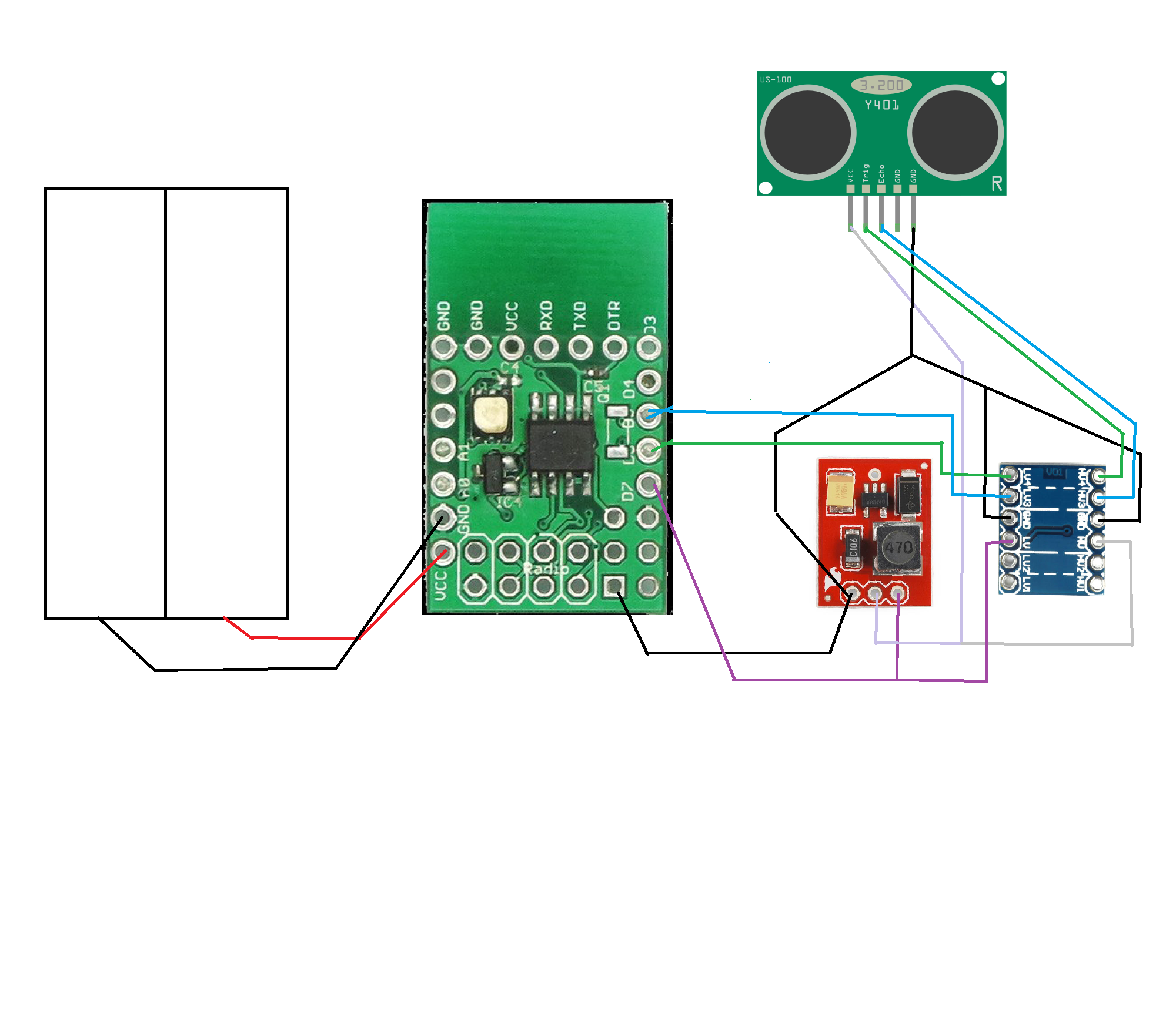
-
Oh, forgot it..
Here is the INO file (beware, it is a 1.5 version of MySensors libraries)
0_1477341898945_DistanceSensebenderMicro.inoQQ.
-
A quick update on this topic.
I have pimped it up using a ME-007 ULS sensor. This one is waterproof, more acurate and can measure longer distances (up to 8 meters).
After some issues related to delay between measures, it works like a charm. -
The finale update !
After numerous tests (using used batteries, adapted software and a lot of patience), it appears that the step up booster was not working under a certain voltage (around 2.7v).
Futhermore, the sleep time before distance measure was very variable.I have questionned myself a lot and finally, my doubts went to the capacity of the Arduino to feed the dc-dc converter with enough current.
To fix this issue, I have used a BC548B transistor with a base resistor of 1K to drive the step-up converter. And, miracle, it works !
My finale test was with a set of used batteries delivering 2 V !Now, I have a sensor that tests distance, temp/hum and battery level every 15 minutes. The average power consumption is 55 µA (25 µA during sleep time and 15 mA for 1 second during measures).
QQ.
-
And here the latest battery graph displaying two things:
- The first phase with not that optimal battery consumption (until Jan, 14th)
- The second one with everything optimized (after Jan, 14th).
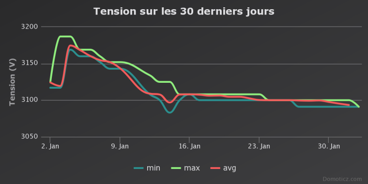
QQ.
-
Very nice project and thanks for sharing. I have a deer feeder in a corner of my yard, and it's always getting empty without me knowing. I'm planning on this exact same type of project to measure the level of corn in the feeder. Would love to see your final schematic and parts list (as it changed across the thread), but no worry if you don't have it as I'm sure I can figure it out.
Thanks again for sharing.
-
I think batteries and sonar distance sensor is not the best, it consumes too much power, since you must measure too often. A better solution if possible is to only get a interrupt with a switch when water tank is empty, then Arduino can sleep forever, or maybe you want to let it wake up once a day to provide a live puls. with a sonar you must check often and spend precious battery for distance measuring. Also there is no need of a DC-DC converter when using the switch, since the DC-DC converter also drains your batteries
Can you use something like this instead?
http://www.ebay.com/sch/sis.html?_nkw=New+Hot+Sale+Small+Liquid+Water+Level+Sensor+Horizontal+Float+Switch+WB&_id=301886450361&&_trksid=p2060353.m2749.l2658 -
Very nice project and thanks for sharing. I have a deer feeder in a corner of my yard, and it's always getting empty without me knowing. I'm planning on this exact same type of project to measure the level of corn in the feeder. Would love to see your final schematic and parts list (as it changed across the thread), but no worry if you don't have it as I'm sure I can figure it out.
Thanks again for sharing.
Thank you @stevebus. It's now live at its outdoor spot measuring the water in my well. It works perfectly :)
I'll post the photos and schemas once I get back from skiing ;)
-
I think batteries and sonar distance sensor is not the best, it consumes too much power, since you must measure too often. A better solution if possible is to only get a interrupt with a switch when water tank is empty, then Arduino can sleep forever, or maybe you want to let it wake up once a day to provide a live puls. with a sonar you must check often and spend precious battery for distance measuring. Also there is no need of a DC-DC converter when using the switch, since the DC-DC converter also drains your batteries
Can you use something like this instead?
http://www.ebay.com/sch/sis.html?_nkw=New+Hot+Sale+Small+Liquid+Water+Level+Sensor+Horizontal+Float+Switch+WB&_id=301886450361&&_trksid=p2060353.m2749.l2658@bjacobse , I do understand your concern ! That was my challenge for the past months. But the combination of digital output to trigger on/off the sensor, low update frequency (15 minutes) and a low power ultrasonic sensor makes it possible (ser posts above).
Qq.
-
Hello @qqlapraline
i want to build exactly this sensor like you do.
Can you help me with a wiring schema and a parts list?Thank you so much!
-
Here is the schematics (freshly made for you :))
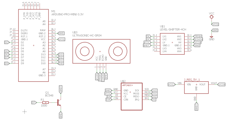
And here the part list:
- Arduino pro mini (3.3v with BOD disabled) or Sensebender Micro
- Ultrasonic sensor: ME007-ULS (available here)
- NRF24L01+ (I use the PA - LNA version for long range communication)
- NPN Transistor: BC548 (the B version if prefered)
- Base resistor: 1k
- 3.3V Step-up Voltage regulator: NCP1402 (available here)
- Logic Level Converter (available here): it says 3.3/5 but actually it's any to any voltage.
- Waterproof case (available here)
And finally here is my code (not cleaned, sorry).
0_1496348693347_DistanceSensebenderMicro.ino
And the Eagle SCH
0_1496348714531_Low power Distance Sensor.schAnd now, I realize that it may have been wise to upload that to openhardware.io :)
Regards,
QQ.
Hello! It looks like you're interested in this conversation, but you don't have an account yet.
Getting fed up of having to scroll through the same posts each visit? When you register for an account, you'll always come back to exactly where you were before, and choose to be notified of new replies (either via email, or push notification). You'll also be able to save bookmarks and upvote posts to show your appreciation to other community members.
With your input, this post could be even better 💗
Register Login