How to get longest battery life
-
@NeverDie My Multimeter is not very good, but I tried to measure the total current. I got 3 values: 0.03mA when sleeping, 0.16mA when PIR triggered and about 18mA when RF is sending. Last is very short an cannot measured with my digital multimeter directly. I measured this value on startup the node when the registration process is longer and I guess it is a similar value when sending.
Here's some additional background that explains some of the "why" behind Heizelmann's approach: http://techgurka.blogspot.com/2013/05/cheap-pyroelectric-infrared-pir-motion.html
In practice, how beneficial is the 100nf capacitor? Have you noticed whether it makes any difference, or is it there just for good measure?
-
Here's some additional background that explains some of the "why" behind Heizelmann's approach: http://techgurka.blogspot.com/2013/05/cheap-pyroelectric-infrared-pir-motion.html
In practice, how beneficial is the 100nf capacitor? Have you noticed whether it makes any difference, or is it there just for good measure?
@Never Thanks for this additional link.
The solution described there is very common, I saw it on some places. The advantage is that no modification of the board is necessary but the disadvantage is that the regulator is still in place and might draw some current back from the 3.3V supply. I prefer to remove unused parts.I had no problems without the 100nf capacitor. It was only a preventive measure.
-
with propper fuses set, the atmega328p can run down to 1.8V, so you do not need 3v3 to run either radio, or the atmega on your arduino board. The PIR might be another story, I haven't looked at the datasheets for that one..
As an example of boards without regulators, you could take a look at the sensebender micro, which is designed to run without regulators at all. I have had 4 sensors running of 2xAA batteries for more than 18 months, they report 66% battery left now..
-
If it could be done cheaply enough, maybe this would be a good use-case for energy harvesting. If the energy harvesting were expensive, though, then it would be cheaper to just use a more energy efficient PIR. So far I've been quite surprised at just how expensive the best energy harvesting chips seem to be.
-
Thanks everyone for the great input. It helps a lot in understanding all of this.
@Heizelmann , Is is really necessary to remove the diode when removing the regulator? Seems like it would give some protection from reverse voltage/current. Does removing it save that much power? I see now that the spot for the regulator is right under the blue cap in your pic.
@tbowmo , I see you mentioned reprogramming the arduino's fuses to switch the operating frequency. Does this require flashing a new reconfigured bootloader or something? I just ordered some 3.3v pro mini boards and some 2 x AA battery holders, so I will try some of this when those arrive.
-
Reprogramming, of fuses is probably needed for low voltage operation, if they have set BOD fuses for 2.5V, then the atmega will not operate under that voltage. Also clock selection is set by programming the fuses. This can be done with another arduino acting as an ISP device.
A diode has a voltage drop across it, so if a diode has 0.5V, and the atmega / radio can work at 1.8V, then the battery voltage needs to be above 2.3V (1.8V operating voltage + diode drop voltage). This means that you can not utilize the full battery life, if you have the diode in the circuit for reverse polarization protection. That is probably why the diode have been removed from the PIR sensor.
@tbowmo A diode typically has a 0.7v drop. The diode that I am talking about is the one on the PIR sensor. The specs for the PIR say that the working voltage is DC 4.5-20V, but I am sure that they are basing that on the fact that it has a 3.3v regulator on it and don't really give the specs for if the regulator (and diode) are removed. I guess I will just have to hook up my bench supply and do some testing to see how low the voltage can get before it stops functioning with the regulator and diode removed.
-
the voltage drop across a diode varies with the technology.. Schottky diodes only have 0.2V drop, while germanium has 0.3V, and silicon has 0.7V.
the 0.5V was just an example.. But the message was, that you have to take the diode drop into account, if you have it inline with the supply, as a reverse polarity protection.. In my example (with 0.5V diode drop) then if you supply your circuit with 2V, then the circuitry after the diode will get 1.5V, which is below the 1.8V minimum operating voltage.
And by removing the diode on the PIR sensor (if it's in the supply line), you can achieve a lower operating voltage.
Here are some measured values (not very precise):
The unmodified HC-SR50: Supply 5.0V, Standby 0.05mA, Tripped: 0.19mA
Regulator and diode removed: Supply 3.0V, Standby 0.03mA, Tripped 0.15mA
Regulator and diode removed: Supply 2.4V, Standby 0.02mA, Tripped 0.11mABelow 2.4 V the Sensor doesn't work reliable.
The voltage drop of the diode depends on the current and is minimum 0.5V.
So if you would like to operate with 3 AA-Batteries it is recommended to remove/shortcut the diode. -
@dbemowsk for an ultra low drop voltage, a ridiculous drop voltage, and regarding reverse polarity protection, at the node level, i would use a P mosfet, a lot better than a diode even a schottky, for low power nodes..
i do this for my nodes, works well ;)Simple: connect GND to your Gate, VBAT to your Source and your 3VCC to the Drain.
When batt is well connected, VBAT normally flows. But when reversed, you have no GND connected to your board.You can think this acting like a resistor then, so with a low Rdson for your mosfet, and U=R.I, you can easily calc this micro volt drop voltage !
About the power consumption of this, it's also ridiculous, as this power consumption does matter in low power "sleep" mode, in uA, power loss is negligeable.Enjoy :)
about the min voltage of this PIR module, if i remember the onboard controller ic is given for 3v min. lucky it can go to 2.4v.
-
Here's a really good youtube video which elucidates what scalz just said:
https://www.youtube.com/watch?v=IrB-FPcv1Dc@scalz Any suggestions as to which p-channel mosfet to pick? Have you any favorites or found any that stand out as just generally better than all the rest at these lower voltages and currents?
-
So I thought since the PIRs that I have say for the chip that the voltage minimum is 3 volts. If I am going to make sensors that run on 2 AA batteries, once the voltage drops a bit the PIR will be useless, thus decreasing the usable battery life for that sensor even though the pro mini and the radio will run at a significantly lower voltage. What about using something like this to step up the voltage just for the PIR, but leaving the radio and arduino directly connected to the battery? This one will work down to 0.8 volts.
Step up booster 1
Or this one which works down to 1.8 volts which is about what the drop off point of the radio and pro mini is. Step up booster 2
I figure the current draw from the PIR would be low enough at 65ma tripped, and a quiscent current of 50ua for the second step up module (can't find quiscent current for the first one) that it shouldn't be too much of a drain on the battery, correct? -
Heizelman says (above) that the sensor works on voltages down to 2.4v. So, use two 1.5v lithium batteries. They have a flatter discharge curve than alkaline batteries.
-
@dbemowsk you don't want to use a step up/step down to run a pir, these generate a lot of noise and can be trouble for radio transmission. With a PIR which is much more sensible it is not a viable option. The only thing you can use to change voltage is a voltage regulator which is less efficient when you have a big voltage drop, but will reduce noise instead of increasing it.
But the best option is I think as NeverDie says, use 2AA with lithium technology, the voltage will stay high enough to run the PIR for most of the capacity of the batteries.I just made a test with 2 nimh AAA and the SR501 runs reliably at 2.7V after removing diode and regulator, but my measurements are higher:
- 36µA in idle mode
- 190µA when triggered.
I did a test with another one, from another supplier (it had different diode an regulator).
- 51µA in idle mode
- 130µA when triggered.
Too high for battery power imho :(
-
the more lifetime, the less maintenance :)
@NeverDie
That's the beauty of mosfets, and Pmosfets :)
i have not really a favorite for this, actually i use what i have at hand. That can be Vishay's (i've multiple ref like si2323 for instance), or cheap ali CJ2305 also work ok etc. -
@Heizelmann said:
@Nca78
Take a battery lifetimecalculator, e.g. like this
and you will see that battery life time is sufficient. In my opinion more than 1 year is enough.I like to use CR2032 batteries :P
And when you use the calculator, you have to adapt the really available capacity to stay over a minimum voltage that will keep the sensor running reliably. If sensors can go down to 2.5 - 2.4V and still run reliably with enough range and sensibility, then with some agressive power management yes you can probably survive about one year with 2AAA.@NeverDie said:
If it could be done cheaply enough, maybe this would be a good use-case for energy harvesting. If the energy harvesting were expensive, though, then it would be cheaper to just use a more energy efficient PIR. So far I've been quite surprised at just how expensive the best energy harvesting chips seem to be.
I will give it a try "the cheap way" :)
5.5V solar panel, small lipo taken from a 2$ mp3 player and CN3063 to manage the charge.
I will need good lighting to be able to charge but I can put the panel in the corner of a window and wires to the sensor at the corner of the window/ceiling which is a good position for a PIR. -
@Nca78 said:
I will give it a try "the cheap way" :)
5.5V solar panel, small lipo taken from a 2$ mp3 player and CN3063 to manage the charge.just make sure you share your results ;)
@korttoma said:
just make sure you share your results ;)
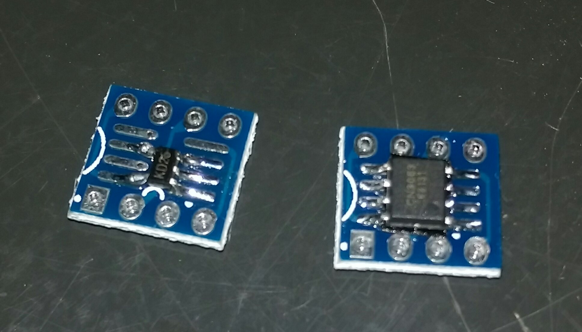
I will of course, but at the moment it's a bit early I just prepared 2 PIRs, 2 panels and soldered CN3063 and MCP73831 on adapter boards. I will compare the two, CN3063 is supposed to be better at this task but you never know...
Hello! It looks like you're interested in this conversation, but you don't have an account yet.
Getting fed up of having to scroll through the same posts each visit? When you register for an account, you'll always come back to exactly where you were before, and choose to be notified of new replies (either via email, or push notification). You'll also be able to save bookmarks and upvote posts to show your appreciation to other community members.
With your input, this post could be even better 💗
Register Login