Battery based atmega328p sensor (no SMD)
-
Hi all,
Well, iam starting to learn to use pcbs. I have now two of above mentioned sensor boards. But im anot sure how i connect the batterrys for the power supply or the Ftdi usb adapter for programming. Is there a kind of cabling diagramm available where i can see how and where which connection must be done?
Many thanks
Markus
-
http://www.psyelmer9.info/blog/may-17th-2012
You may need to set the fuses to disable bod and burn a bootloader with an ISP-Adapter.
-
Sorry i mean this one here
https://www.openhardware.io/view/5/Battery-based-atmega328p-sensor-no-SMD
And how must i connect the ftdi usb adapter to flash this board...Thx
M
-
Sorry i mean this one here
https://www.openhardware.io/view/5/Battery-based-atmega328p-sensor-no-SMD
And how must i connect the ftdi usb adapter to flash this board...Thx
M
-
I found a label FTDI on one picture of the PCB. 😀
I encourage you to read articles about arduino on breadboard and dive deeper or buy complete solutions like the sensebender micro.
-
And how should i connect correctly the battery for the power supply? A complete cabeling diagramm would be great... :-)
@Markus. The ftdi connection is marked on the board. @GertSanders used a standard ftdi connector with 6 pins and "black" and "green" marking.
-
@Markus. The ftdi connection is marked on the board. @GertSanders used a standard ftdi connector with 6 pins and "black" and "green" marking.
@AWI many thanks thats now clear for me. Sorry for all this questions but I've started to learn.... :-(
I can see on the board some 3,3 V Connections beside VCC and VBAT. Where is now the correct place to connect the Battery as power supply ?Thanks
Markus
-
@AWI many thanks thats now clear for me. Sorry for all this questions but I've started to learn.... :-(
I can see on the board some 3,3 V Connections beside VCC and VBAT. Where is now the correct place to connect the Battery as power supply ?Thanks
Markus
@Markus. From my perspective @GertSanders has done a great job in documenting the board, but there are many options.
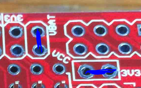 This is the place where you determine what is connected to Vcc and battery. If you don't use an external regulator, just make connections indicated and any 3v3, Vcc and vbat connection can be used.
If you operate from 2 AA cells then probably your next question is leading to burning the fuses for operating at low voltages ;-) -
yes thats the idea to operate themwith 2xAA cells.... ;-) So it means that I can use each GND conenction for Minus and each 3V3 connction for plus....
Ohhh hell.. :-) And what exactly do you mean with "burning the fuses for operating at low voltages" ?? Thought I can simple connect my Minus from the Battery to a Connection on the board and also the Plus to get it working with Batterys...:-(
What I also not understand is .."If powered by two AA or AAA batteries, the circuits VCC and 3V3 should be connected. This is done by shorting jumper "J1"." ...
Hope I will understand all this in the next 100 years .. :-) -
yes thats the idea to operate themwith 2xAA cells.... ;-) So it means that I can use each GND conenction for Minus and each 3V3 connction for plus....
Ohhh hell.. :-) And what exactly do you mean with "burning the fuses for operating at low voltages" ?? Thought I can simple connect my Minus from the Battery to a Connection on the board and also the Plus to get it working with Batterys...:-(
What I also not understand is .."If powered by two AA or AAA batteries, the circuits VCC and 3V3 should be connected. This is done by shorting jumper "J1"." ...
Hope I will understand all this in the next 100 years .. :-)@Markus. "shorting jumper J1' is equivalent to the right blue line in my last post.
"fuses for operating at low voltages" means you need to program the AVR processor so that it can operate at low voltages (< 2.7 volt). this needs to be done with a special programming circuit. So you either keep your batteries above 2.7 volt or dive into the world of Fuse programming. -
@Markus. "shorting jumper J1' is equivalent to the right blue line in my last post.
"fuses for operating at low voltages" means you need to program the AVR processor so that it can operate at low voltages (< 2.7 volt). this needs to be done with a special programming circuit. So you either keep your batteries above 2.7 volt or dive into the world of Fuse programming.
Hello! It looks like you're interested in this conversation, but you don't have an account yet.
Getting fed up of having to scroll through the same posts each visit? When you register for an account, you'll always come back to exactly where you were before, and choose to be notified of new replies (either via email, or push notification). You'll also be able to save bookmarks and upvote posts to show your appreciation to other community members.
With your input, this post could be even better 💗
Register Login