Cannot send ID
-
Hi. I am new to MySensors.
I made a serial gateway and relay actuator. I do not have a controller yet. I try manually set the Relay-unit ID. Serial data I collected from gateway is:
0;0;3;0;14;Gateway startup complete.
0;0;3;0;9;read: 255-255-0 s=255,c=3,t=3,pt=0,l=0:
255;255;3;0;3;
0;0;3;0;14;Gateway startup complete.After I reset gateway; I reset relay-node (It prints: "req node id" on its serial). I get is the above text. In a second or so I manually send text "255;255;3;0;1"+LineFeed
All I get is a stuck gateway?!?!
What to do? How to manually assign ID number?
I use unmodified scatches.
Tnx4help. -
i have the exact same problem.
i use freedomotics as my controller with mysensors plugin and when my sensor asks for a unique ID the controller never responds. how come the controller never responds?bump
-
"255;255;3;0;1"+LineFeed
Looking at http://www.mysensors.org/build/serial_api you can decode this message:
- 255;255 = node-id and child-sensor-id. 255;255 means something like broadcast
- 3 = message-type: Internal
- 0 = ack, so No ack
- 1 = sub-type for Internal sub-type 3 means I_ID_REQUEST
To provide an ID you need to send a I_ID_RESPONSE message or, probably better, use one of the controllers that support MySensors.
-
Hi.
I have figured it out why I still have problems with nrf24l01+ modules. They simply do not work well. Tx success is 1 in 5-10. If I change them with NRF24L01+PA+LNA modules communication works well (success rate 1/3).
I have a 47uF cap next to modules and separate 3.3V switching supply for them. I measure something from 2.6-3.3V which is enough as specs declare. AVRs are pro mini 5V. Testing environment: modules are 20cm apart.Any idea?
@Hacker007
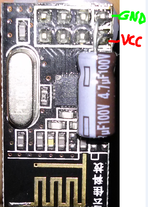
Hi, you use a 47uF Cap?
I've soldered a 4.7uF capicator for decoupling directly between the GND and VCC PIN's on the NRF24 chip which works great. The description on http://www.mysensors.org/build/connect_radio says 4**.**7uF, but you use a 47uF capicator, maybe that is the problem. -
Hi.
I have figured it out why I still have problems with nrf24l01+ modules. They simply do not work well. Tx success is 1 in 5-10. If I change them with NRF24L01+PA+LNA modules communication works well (success rate 1/3).
I have a 47uF cap next to modules and separate 3.3V switching supply for them. I measure something from 2.6-3.3V which is enough as specs declare. AVRs are pro mini 5V. Testing environment: modules are 20cm apart.Any idea?
@Hacker007 said:
Hi.
I have figured it out why I still have problems with nrf24l01+ modules. They simply do not work well. Tx success is 1 in 5-10. If I change them with NRF24L01+PA+LNA modules communication works well (success rate 1/3).
I have a 47uF cap next to modules and separate 3.3V switching supply for them. I measure something from 2.6-3.3V which is enough as specs declare. AVRs are pro mini 5V. Testing environment: modules are 20cm apart.Any idea?
I'd say the root couse is the swtiching supply rather than the capacitor. Try with a separate 2x1,5V battery supply instead. If that works well and you still want your other supply you can try to complement with low-ESR caps (like 1-100pF ceramic caps).
-
It' always interesting to see how different solutions work for different people while the same exact solutions don't for others. In my environment using 2 AA batts with a step module, the ONLY way I could get stable transmission with MySensors 1.4 was with a 47uf cap.
Here is my sorted tale of power management gone wrong...
Not sure how / what power supply you are using, (most wall warts are switching) but I would agree with @m26872 , take a very close look at the power supply. If you are building your own up, you can use the solution I've worked out in this thread as it works perfectly for me. (make sure you read the last post)
-
Hi. Thank you all for advice.
I have tried ceramic caps on small 24l01 but no success. I have not tried battery supply yet, but I will when time allows it. I installed 1.4.1 version, but did not see any difference... I continue to use NRF24L01+PA+LNA. Will change to small 24L01 when I achieve success.For my bench supply I use old PC ATX supply unit. I use 12V. Both Mysensor-units get voltage from 12V to their RAW pin. 12V also goes to my KIS-3R33S modules and 3V3 afterwards via 47uF elco to NRF. In both sketches I use delay(1000) as the first command for the NRF power supply to settle(?!?) then I use gw.begin...
There is something new. If my hand is close to antenna of button/relay-sketch-unit (10cm or closer), the TX/RX is better (i.e. working). No difference if I touch gateway unit. Any idea? Maybe the whole problem is interference...
ADDED: I have tried battery supply. Instead of 12V from old ATX PC supply I have tried 9V battery. There is no difference. Amplified NRF communication is 100% if both LNA units are used. If I mix them, or use only small 24L01+ all I get is "fail".
Rok
Hello! It looks like you're interested in this conversation, but you don't have an account yet.
Getting fed up of having to scroll through the same posts each visit? When you register for an account, you'll always come back to exactly where you were before, and choose to be notified of new replies (either via email, or push notification). You'll also be able to save bookmarks and upvote posts to show your appreciation to other community members.
With your input, this post could be even better 💗
Register Login