HC-SR501 3.3V randomly sends tripped when radio is on


  • Hi all,

    I've read a lot of posts about battery-powered motion/temp/humidity sensors.
    I'm new to electronics and programming, but I've already had sucess in setting everything up.

    Below is my wiring.

    ![0_1490045167603_pir-dht22-battery-sketch.PNG](Uploading 100%)

    I haven't modified the arduino pro mini 3.3V version for a battery optimizied use.
    The VCC is directly connected to the h-pad (wire soldered to h-pad) of the HC-SR501.
    The Temp/Humidity sensors is a DHT22.

    The node should do the following:
    If the arduino woke up from interrupt, then send only the tripped status of the motion sensor.

    if the arduino woke up from the sleep timer (1 min for testing), then send humidity, battery and temperature, but only if the values changed more than the treshold.

    Everything works well, the node sends humidity, battery and temperature when the sleep timer ended and does this only if it changed more than my defined threshold.
    The node also detects correctly that it woke up from interrupt and sends only the motion sensor value.

    The problem is that it looks like the radio triggers the motion sensors or something like that.
    Everytime when the motion sensor detects motion, it sends 2-3 tripped messages in a row, if I understood correctly, this means the arduino wakes up from the interrupt, then sends the message and goes back to sleep and then immediately wakes up and sends the message again, right?
    Also when the arduino wakes up from the sleep timer, it sends the temp/hum/battery values and sometimes, with random behaviour also the motion tripped value.

    Where is the problem? Wiring? Coding? I tried dozens of codes and always the same behaviour ๐Ÿ˜ž
    Below my sketch:

    #include <SD.h>
    
    // Enable debug prints
    #define MY_DEBUG
    
    // Enable and select radio type attached 
    #define MY_RADIO_NRF24
    
    
    //define Node ID before include mysensors.h
    #define MY_NODE_ID 200
    
    #include <SPI.h>
    #include <MySensors.h>
    #include <readVcc.h>  
    #include <DHT.h>  
    
    
    #define CHILD_ID_HUM 0
    #define CHILD_ID_TEMP 1
    #define CHILD_ID_MOT 2
    
    //define PINS
    int BATTERY_SENSE_PIN = A0;  // select the input pin for the battery sense point
    #define DHT_DATA_PIN 5
    #define DIGITAL_INPUT_SENSOR 3   // The digital input you attached your motion sensor.  (Only 2 and 3 generates interrupt!)
    #define INTERRUPT DIGITAL_INPUT_SENSOR-2 // Usually the interrupt = pin -2 (on uno/nano anyway)
    
    #define MIN_V 1900 // empty voltage (0%)
    #define MAX_V 3000 // full voltage (100%)
    
    unsigned long SLEEP_TIME = 60000UL; // Sleep time between reads (in milliseconds)
    int oldBatteryPcnt = 0;
    
    
    //Reporting Thresholds
    #define HUMI_TRANSMIT_THRESHOLD 3.0  // THRESHOLD tells how much the value should have changed since last time it was transmitted.
    #define TEMP_TRANSMIT_THRESHOLD 0.5
    #define BATTERY_TRANSMIT_THRESHOLD 2.0
    
    //Parameters
    DHT dht;
    float lastTemp = 0 ;
    float lastHum = 0 ;
    int count = 0;
    boolean lastTripped = false ;
    boolean metric = true; 
    MyMessage msgHum(CHILD_ID_HUM, V_HUM);
    MyMessage msgTemp(CHILD_ID_TEMP, V_TEMP);
    MyMessage msgMot(CHILD_ID_MOT, V_TRIPPED);


    void setup()  
    { 
     // use the 1.1 V internal reference
    #if defined(__AVR_ATmega2560__)
     analogReference(INTERNAL1V1);
    #else
     analogReference(INTERNAL);
    #endif
      dht.setup(DHT_DATA_PIN); 
    
      // Send the Sketch Version Information to the Gateway
      sendSketchInfo("Humidity/Motion", "1.0");
    
      pinMode(DIGITAL_INPUT_SENSOR, INPUT);      // sets the motion sensor digital pin as input
     
      // Register all sensors to gw (they will be created as child devices)
      present(CHILD_ID_HUM, S_HUM);
      present(CHILD_ID_TEMP, S_TEMP);
      present(CHILD_ID_MOT, S_MOTION);
       
      metric = getControllerConfig().isMetric;
    }
    
    void loop()      
    
    {  
      //-1 woke up from sleep timer, 1 woke up from pin interrupt
       static int8_t wakeup; 
       
      //////////////////////////////////////////////////////////////////////////
      // Battery
      /////////////////////////////////////////////////////////////////////////
       int sensorValue = analogRead(BATTERY_SENSE_PIN);
       #ifdef DEBUG
       Serial.println(sensorValue);
       #endif
       
       // 1M, 470K divider across battery and using internal ADC ref of 1.1V
       // Sense point is bypassed with 0.1 uF cap to reduce noise at that point
       // ((1e6+470e3)/470e3)*1.1 = Vmax = 3.44 Volts
       // 3440/1023 = Volts per bit = 3.363075
       float batteryV  = sensorValue * 3.363075;
       //int batteryPcnt = ((batteryV - MIN_V) / (MAX_V - MIN_V))*100;
       int batteryPcnt = min(map(readVcc(), MIN_V, MAX_V, 0, 100), 100);
       
       #ifdef DEBUG
       Serial.print("Battery Voltage: ");
       Serial.print(batteryV);
       Serial.println(" V");  
    
       Serial.print("Battery percent: ");
       Serial.print(batteryPcnt);
       Serial.println(" %");
       #endif
    
       float diffBattery = abs(oldBatteryPcnt - batteryPcnt);
       if(wakeup == 1){
       }
       else if (diffBattery > BATTERY_TRANSMIT_THRESHOLD) {
         // Power up radio after sleep
       sendBatteryLevel(batteryPcnt);
         oldBatteryPcnt = batteryPcnt;
       }
    
      /////////////////////////////////////////////////////////////
      //Motion
      ////////////////////////////////////////////////////////////
      boolean tripped = digitalRead(DIGITAL_INPUT_SENSOR) == HIGH; 
     
      if(wakeup == -1){
      }
      else if (tripped != lastTripped ) {      
        Serial.println(tripped);
        send(msgMot.set(tripped?"1":"0"));  // Send tripped value to gw
      }
    
    
      ////////////////////////////////////////////////////////////////////
      //Temp and Humidity
      ///////////////////////////////////////////////////////////////////
      delay(dht.getMinimumSamplingPeriod());
    
      float temperature = dht.getTemperature();
      float diffTemp = abs(lastTemp - temperature);
      
      float humidity = dht.getHumidity();
      float diffHum = abs(lastHum - humidity);
      
      if (isnan(temperature)) {
        Serial.println("Failed reading temperature from DHT");
      }else if (wakeup == 1){
      }
      else if(diffTemp > TEMP_TRANSMIT_THRESHOLD) {
        lastTemp = temperature;
        if (!metric) {
          temperature = dht.toFahrenheit(temperature);
        }
        send(msgTemp.set(temperature, 1));
        Serial.print("T: ");
        Serial.println(temperature);
      }
      
      if (isnan(humidity)) {
          Serial.println("Failed reading humidity from DHT");
      } else if (wakeup == 1){
      }
      else if(diffHum > HUMI_TRANSMIT_THRESHOLD) {
          lastHum = humidity;
         send(msgHum.set(humidity, 1));
          Serial.print("H: ");
          Serial.println(humidity);
      }  
      //////////////////////////////////////////////////////////////////////
      // Sleep until interrupt comes in on motion sensor. Send update every two minute. 
      wakeup=sleep(digitalPinToInterrupt(DIGITAL_INPUT_SENSOR), RISING, SLEEP_TIME);
    }
    

  • Mod

    I fixed your code tags you were a little happy with those ๐Ÿ™‚

    How are you powering the node and sensor?


  • 0_1490048234979_pir-dht22-battery-sketch.PNG

    Here is the wiring. Didn't work in the first post. It is all powered by two AA batteries.


  • Mod

    That's quite strange, have you tried a different sensor and radio?


  • I had what I suspect to be the same issue a while back, and it took me ages to debug.

    I haven't looked at your code or reviewed the circuit diagrams in detail, but the symptoms sound spot-on, so I'm reasonably confident that this is what is going on.

    For backround, the HC-SR501 is a very sensitive trigger that sets up a delicate balance between the two sides of the IR receiver, and then waits for that to get out of balance (i.e. from one side getting more or less light). Once things are out of balance, the sensor trips and you get an interrupt. Woohoo!

    Now, the problem here is that even though we like to think of power and ground as "constant", in actuality any load that is not constant is going to raise or lower the power rail voltage a bit. And if you have a relatively "heavy" load (like an active radio and Arduino processor) that suddenly goes "off", the power rail is going to spike high for a brief time, since the batteries and regulators are all whirring along trying to supply that higher load. That voltage spike then rips through the HC-SR501 (which, as you recall is already spring-loaded looking for minute imbalances), and tips the scales, causing a trigger and what ends up looking like a motion event. The interrupt pin on the Arduino goes high (or low) and wakey-wakey!

    (Keep in mind that I don't have access to an o-scope, so a lot of this is from thought experiment, conjecture and fiddling with various elements, but I'm reasonably certain that's at least close to what's happening.)

    I also suspect that this is exacerbated by using a lower voltage (3.3V vs 5V), tying directly to the 3.3V pin on the HC-SR501 (bypassing extra voltage regulation), and using batteries as a power source (they've got their own inefficiencies as a voltage source).

    So anyway, all that being said, the way I worked around this on my devices was to "stagger" the sleep. First I would power down the radio, then wait "a bit" (100ms or so?) for power to stabilize, then do the actual sleep() call to put the Arduino to sleep.

    This was with MySensors 1.4, which I think made it a little easier to get at the internal radio to do a powerDown() call. But I think it's still possible to get at the raw radio. I just don't recall off the top of my head how to do with with MyS 2.x.

    Anyway... hopefully that saves you a lot of head scratching. Digital components are awesome as building blocks, but darn it if analog issues creep in sometimes...


  • Yes, I've tried three different radios and two motion sensors, always the same behaviour.


  • Mod

    What's the size of the cap?


  • @gohan
    The capacitor is 47ยตf.

    @rickmontana83
    Do you happen to know where I could find this information?


  • Mod

    If you have one, try a 100uF. Once I solved this way


  • @gohan I seem to remember trying that, and gave up when 470uF wasn't enough. ๐Ÿ™‚ That being said, it's an easy enough thing to try.

    @burningstone I'd search around the MySensors library code for the implementation of the sleep() routines. They'll need to call the radio shutdown somehow. Doing a quick drill-down, I see:

    MySensorsCore.cpp defines the internal _sleep() routine, which ends up calling transportPowerDown() (to do the power-down of the radio in a hardware-independent way). This ends up calling into transportPowerDown() in MyTransportNRF24.cpp (for your radio type), which calls the RF24_powerDown() routine.

    I would think that's probably the one you want to call.


  • @rickmontana83
    Sorry, I don't understand what I have to do now.
    Do I have change the sketch to:

    RF24_powerDown();
    wakeup=sleep(digitalPinToInterrupt(DIGITAL_INPUT_SENSOR), RISING, SLEEP_TIME);


  • Mod

    If I am not mistaken, calling the sleep function already powers down radio


  • @gohan
    Yes you are right, but I need to poweroff the radio and then wait some ms and then go into sleep interrupt if I understood @rickmontana83 correctly.

    @rickmontana83
    How can I call these functions from my sketch? Do I need to change the mysensor library files?


  • Mod

    @burningstone I didn't read the whole thread, but quickly scanning over it I understood you are powering the pir with 2xAA cells. If that's the case it is not going to work. The pir needs at least 3xAA cells to function correctly when you bypass its regulator.


  • @Yveaux
    Could you please explain why this will not work?
    Because the pir sensor detects motion perfectly fine, the only problem are the false triggers, which occur when the radio sends the signal to the gateway.
    I also saw some guys that run the exact same pir and arduino pro mini 3.3V version on 2xAA batteries.


  • Mod

    @burningstone the biss0001 chip on the pir is rated for 3..5V operation. If you use it outside its allowed range you can expect undefined behavior, e.g. false triggers.

    These sensors are very sensitive to power supply. Even with a good supply within spec behavior is sometimes strange, to say the least...


  • @Yveaux
    So what would you suggest? Adding a third AA-battery?
    I just can't understand why some people got this pir sensor working on 2 AA batteries and without false triggers.


  • Mod

    @burningstone pure luck? It's all about tolerances. Let's see if it still works for them once the environment temperature changes, the pir ages, the battery levels drop, the radio sends more data, etc, etc.
    A simple fix is to power the pir from 3xAA and the arduino and radio from only 2xAA.
    Search the forum, I've already explained it in another thread.


  • @Yveaux
    So i would need 5 batteries in total??
    Seems like overkill to me, and the sensor would become quite big ๐Ÿ˜ž


  • Mod

    @burningstone no, just 3xAA.
    Power the arduino and radio from the first 2 only.


  • @Yveaux
    I found your other post here in the forum regarding the 3AAA batteries. Could you please explain how I do this?
    Do I need to buy a battery pack for 3 batteries or is it possible do modify the battery pack I already have?
    Sorry for bothering you with this type of questions, I just recently started with this.


  • Mod

    @burningstone Here's a schematic representation of what I mean:

    0_1490118551766_upload-52d98145-abd5-4638-aec4-e113815f2474

    The red wire w.r.t. ground (black wire) will supply max. 4.5V (3xAA), the yellow one w.r.t ground will supply max. 3V.
    The load of the Arduino and nRF24 are small, so all batteries will more or less drain equally fast.

    It can easily be implemented by soldering an extra wire (the yellow one) to a 3xAA battery holder:

    0_1490118888468_upload-ff89e5ca-5fe9-49a3-93ce-f0d117426868

    Try it, and verify the output voltages with a DMM!


  • @Yveaux
    Thank you very much.
    I'll order a battery pack for 3 batteries, currently I have only a pack for 2 batteries.

    How long does it take approximately till the batteries are empty? I know that it depends on how frequent the sensor gets triggered, but maybe you can tell me some average values.


  • Mod

    @burningstone I have one next to my front door for exactly one year now, which triggers many times per day.
    Battery has only decreased from 100% to 89% ! ๐Ÿ‘


  • @Yveaux
    That sounds like exactly what I want ๐Ÿ™‚

    Would it be possible to add a dht22 or would this interfere with the pir?


  • Mod

    @burningstone if you don't want to wait for the 3xAA holder you can do like this
    0_1490128739892_pir.png


  • @mfalkvidd
    Awesome! How do i connect the wires to the battery? Solder them or what?


  • Mod

    @burningstone the ugly way is to solder ๐Ÿ™‚ It works, but becomes a quite permanent solution.
    I prefer using scotch tape. Or, if you have an extra 2xAA holder you can do like this (skip the fourth battery):
    0_1490130384837_pir2.png


  • @mfalkvidd
    And how can i tape the wire on the side of the battery holder? My battery holder package already has two wires connected like in the fritzing pictures.


  • Mod

    Or put the wire between the battery and spring/contact


  • Mod

    @burningstone tape a wire directly on the battery, or solder to the battery or the holder.
    Look what you have lying around and be creative!
    That's what MySensors is about!


  • @Yveaux
    Sorry I have been a long time away due to exams.
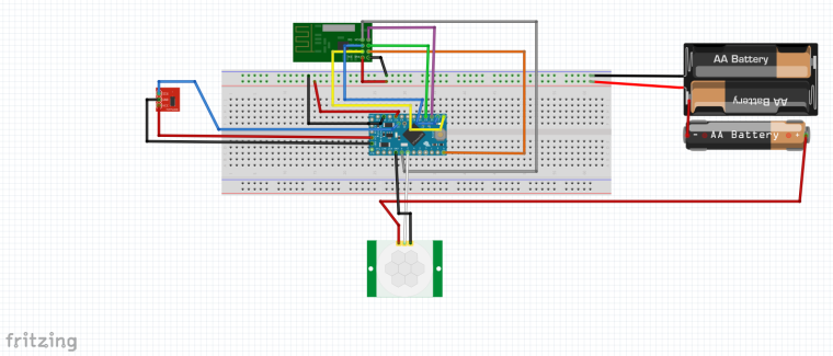
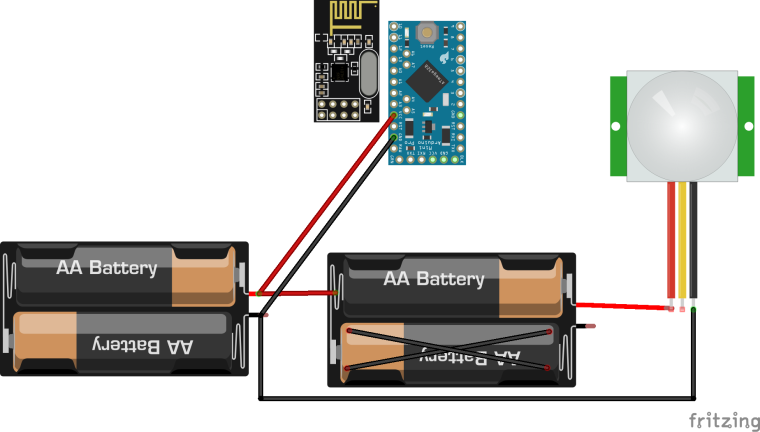
    Now I finally have time to spend for mysensors ๐Ÿ™‚

    I tried your approach with the three batteries. My setup looks like this:

    0_1497178432582_Motion Light.PNG

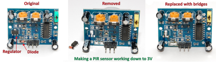
    I modified the HC-SR501 as shown below:

    0_1497178475013_HC-SR501.jpg

    The sketch is pretty simple, it sends the motion and the light level and then goes to sleep with interrupt for 30 minutes. I still get the false positives whenever the arduino doesn't wake up from intrerrupt.

    What am I doing wrong?


  • Mod

    Try adding a cap on the power of the pir sensor, start from 10uf and try to increase up to 100uf and see if it gets better


  • Mod

    @burningstone what MySensors version are you running? I did solve an issue with waking from interrupts in 2.2 beta, that's still present in 2.1.x. This might be what's bothering you...


  • Hardware Contributor

    @burningstone You probably want to find the root cause to this but, as a quick fix, have you tried software-blocking the false trip with an additional sleep before the interrupt-activating sleep? Something like sleep(3000); before the last sleep(...). I do it with success for my mini-pirs.


  • @Yveaux @gohan
    I updated the library to 2.2 and I put a 47uf cap between ground and vcc of the pir (hope that's what you mean't) and now it works.

    Thanks for your help!

    I soldered now everything onto a pcb and now the pir doesn't work. I feel like giving up, didn't think that it would be that hard for me to build one stable node. I spent almost 2 hours soldering and assembling and now it doesn't work ๐Ÿ˜ž


  • @m26872 Thanks for this suggestion. I have had some PIR sensors that work normally and others that always trip immediately after going to sleep. It was really frustrating me. Adding the short sleep without interrupts solved this for me.


  • Mod

    the standard cheap PIR sensors are known to trigger false positives because of power fluctuations


  • @burningstone Check connections with a continuity tester and measure your voltages coming to the arduino and PIR. When checking continuity, check directly from the jack on the PIR and/or temp sensor to the pro mini terminals, and also check pins near the connections for any possible shorts.


Log in to reply
 

Suggested Topics

22
Online

11.2k
Users

11.1k
Topics

112.5k
Posts