Driveway motion light
-
So my latest project has been to replace an X-10 FloodCam (VT38A) motion sensor light controller with a MySensorized controller. I had been having some problems with the light getting stuck on for very long periods of time. The other issue was that this, like a lot of my other X-10 modules, I couldn't get a status reading from it, which was annoying. It had a built in camera which was wireless, but you needed an X-10 receiver to use it, and where I had my equipment, the picture was crappy at best.
I had some relay modules that were given to me by a friend, so I thought I would use one on this node. The node has 3 parts, the motion sensor, an LDR sensor, and the relay module. The concept is simple. The LDR is used to detect dusk/dawn to only allow the motion to turn on the relay/light when it is dark outside. I had a project box that I bought a while back for another project that I never used, so I figured this was the perfect project for it, but the trick was making everything fit.
The relay module was a 12 volt module, so I needed a 12 volt supply. I opted for the HiLink HLK-PM12. On the 5 volt pro mini that I was using, the regulator would get quite hot with 12 volts on the RAW input, so I decided to use a second regulator (LM7808) to drop the RAW voltage from 12 to 8 volts. It meant that I was regulating the voltage twice, but it worked well.
I took the old mounting tube off of the old floodcam and used it on the new setup. That now lets me swivel and point the sensor box to wherever I need it. It also lets me run my 120 volt power wires into the light assembly. The power wires are:
- Black - Hot
- White - Neutral
- Blue - Switched hot for lights
One other thing that can't be seen in the pics is that I put hot glue over most of the screws and nuts that were coming out of the plastic case. I did this to help prevent them from getting wet and rusting. I did this at the last minute before I installed it which is why it can't be seen in the pics.
Here are some pics of the setup.


-
For those interested, here is version 1.0 of the code written for MySensors 2.0. This presents all 3 devices to the controller, in my case Domoticz.
/**
 * The MySensors Arduino library handles the wireless radio link and protocol
 * between your home built sensors/actuators and HA controller of choice.
 * The sensors forms a self healing radio network with optional repeaters. Each
 * repeater and gateway builds a routing tables in EEPROM which keeps track of the
 * network topology allowing messages to be routed to nodes.
 *
 * Created by Henrik Ekblad <henrik.ekblad@mysensors.org>
 * Copyright (C) 2013-2015 Sensnology AB
 * Full contributor list: https://github.com/mysensors/Arduino/graphs/contributors
 *
 * Documentation: http://www.mysensors.org
 * Support Forum: http://forum.mysensors.org
 *
 * This program is free software; you can redistribute it and/or
 * modify it under the terms of the GNU General Public License
 * version 2 as published by the Free Software Foundation.
 *
 *******************************
 *
 * REVISION HISTORY
 * Version 1.0 - Henrik Ekblad
 *
 * DESCRIPTION
 * Example sketch showing how to control physical relays.
 * This example will remember relay state after power failure.
 * http://www.mysensors.org/build/relay
 */

//Set up the nRF24L01+
#define MY_RADIO_NRF24

#include <SPI.h>
#include <MySensors.h>

#define SKETCH_NAME "Driveway motion light"
#define SKETCH_VERSION "1.0"

#define RELAY_PIN       3  // Arduino digital I/O pin for the relay
#define LIGHT_LEVEL_PIN A0 // Arduino analog I/O pin for the light level sensor
#define MOTION_PIN      5  // Arduino digital I/O pin for the motion sensor

#define RELAY_ID        1 // Relay child ID
#define LIGHT_LEVEL_ID  2 // Light level sensor child ID
#define MOTION_ID       3 // Motion sensor child ID

#define RELAY_ON        1  // GPIO value to write to turn on attached relay
#define RELAY_OFF       0 // GPIO value to write to turn off attached relay

// Sleep time between reads (in milliseconds)
unsigned long SLEEP_TIME = 100000;

unsigned long T = 1;

// Initialize light relay
MyMessage relay_msg(RELAY_ID, V_LIGHT);
// Initialize light sensor
MyMessage light_level_msg(LIGHT_LEVEL_ID, V_LIGHT_LEVEL);
// Initialize motion message
MyMessage motion_msg(MOTION_ID, V_TRIPPED);

int lastLightLevel;
bool lastMotion;
int relay;
int lastRelay;

/**
 * presentation - Present the garage door sensor
 */
void presentation() {

  sendSketchInfo( SKETCH_NAME, SKETCH_VERSION );

  // Register the relay to the gateway
  present(RELAY_ID, S_LIGHT);
  // Register the light level sensor to the gateway
  present(LIGHT_LEVEL_ID, S_LIGHT_LEVEL);
  // Register the motion sensor to the gateway
  present(MOTION_ID, S_MOTION);
} //End presentation

void setup() {
  // Then set relay pins in output mode
  pinMode(RELAY_PIN, OUTPUT);
  // Flash the relay 4 times to indicate initialization
  for ( int i = 0; i < 4; i++) {
    digitalWrite(RELAY_PIN, RELAY_ON);
    delay (500);
    digitalWrite(RELAY_PIN, RELAY_OFF);
    delay (500);
  }
  // Set relay to last known state (using eeprom storage)
  relay = loadState(RELAY_ID) ? RELAY_ON : RELAY_OFF;
  digitalWrite(RELAY_PIN, relay);

  // Define the LDR pin for analog input
  pinMode(LIGHT_LEVEL_PIN, INPUT);

  // Define the motion sensor pin for digital input
  pinMode(MOTION_PIN, INPUT);
} //End setup


void loop() {
  // Read digital motion value
  bool motion = digitalRead(MOTION_PIN) == HIGH;

  if (motion != lastMotion) {
    // Send tripped value to gw
    send(motion_msg.set(motion ? "1" : "0"));
    lastMotion = motion;
  }

  // Read the value measured from the LDR
  int16_t lightLevel = analogRead(LIGHT_LEVEL_PIN)/10.23;

  if (lightLevel < 10 && motion && relay == RELAY_OFF) {
    send(relay_msg.set(RELAY_ON));
    digitalWrite(RELAY_PIN, RELAY_ON);
    relay = RELAY_ON;
  } else if (!motion && relay == RELAY_ON) {
    send(relay_msg.set(RELAY_OFF));
    digitalWrite(RELAY_PIN, RELAY_OFF);
    relay = RELAY_OFF;
  }

  T++;
  if (T > SLEEP_TIME) {
    T = 1;
    Serial.print("Motion: ");
    Serial.println(motion);
    if ((lightLevel != lastLightLevel)) {
      send(light_level_msg.set(lightLevel));
      // Display the value in the serial monitor
      Serial.print("Light Level: ");
      Serial.println(lightLevel);
      lastLightLevel = lightLevel;
    }
  }
} //End loop

void receive(const MyMessage &message) {
  // We only expect one type of message from controller. But we better check anyway.
  if (message.type==V_LIGHT) {
     // Change relay state
     digitalWrite(RELAY_PIN, message.getBool() ? RELAY_ON : RELAY_OFF);
     // Store state in eeprom
     saveState(message.sensor, message.getBool());
     // Write some debug info
     Serial.print("Incoming change for sensor:");
     Serial.print(message.sensor);
     Serial.print(", New status: ");
     Serial.println(message.getBool());
   }
} //End receive
On the device, the motion sensor will only turn on the relay/light when the LDR lux level is below 10. This ensures that the light will only come on at night. However, with the presentation of all 3 devices to the controller, the device can be used for much more. With scripting, I can use the sensed lux level to do other functions based on the light level by my driveway if I want. Likewise, the motion sensor will still register motion to the controller so if at some point I install a camera outside to monitor my driveway and/or front door (which I plan to do). I can use the motion sensor to start the camera recording at any time. And last, I have manual control of the light if I need at any point in the day.
Currently I have the light set to only turn on at a hard coded lux level of 10. If I find that this needs to be adjusted, I may modify the code so that I can set the lux threshold level from the controller using S_INFO or something similar and have it store that value at the device.
-
@dbemowsk Hi and thanks for the sketch! I don't know if you still using this setup - I tried it and it works flawlessly. But (there is always a "but"), I am having problems lighting up the relay when light levels drop. My LDR sensor reports light the opposite it needs to be reported; meaning I get 100 when no light at all and 0 light level when I shine a light into the sensor (full light situation).
Surely I resolved the relay firing up thing by changing
if (lightLevel < 10 && motion && relay == RELAY_OFF)
into
if (lightLevel > 90 && motion && relay == RELAY_OFF)
and the relay works, but I really love to use the right LDR Level on my Domoticz setup so a little help will be really appreciated.
Is this something that my LDR sensor is faulty or is this something it could be resolved by modifying the sketch?
Thanks in advance!
@BeniK Your LDR sensor is most likely not faulty. To invert the values read by the sensor, all you need to do is reverse how it is wired to your reference power. There are two ways to wire these:
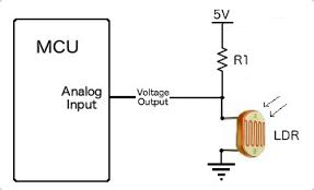
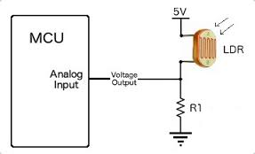
I am pretty sure that you have yours wired like the first one. To invert the values, switch your + and - on the LDR voltage divider. Basically, which ever way you have it wired, wire it the other way and my code should work.Here is a great page that explains using LDRs with an arduino. https://learn.adafruit.com/photocells/using-a-photocell
Vera Plus running UI7 with MySensors, Sonoffs and 1-Wire devices
Visit my website for more Bits, Bytes and Ramblings from me: http://dan.bemowski.info/ -
@BeniK Your LDR sensor is most likely not faulty. To invert the values read by the sensor, all you need to do is reverse how it is wired to your reference power. There are two ways to wire these:
I am pretty sure that you have yours wired like the first one. To invert the values, switch your + and - on the LDR voltage divider. Basically, which ever way you have it wired, wire it the other way and my code should work.Here is a great page that explains using LDRs with an arduino. https://learn.adafruit.com/photocells/using-a-photocell
-
@dbemowsk Thnk You very much for your help!
Yhe sensor breakout board I am using is this one on the pictures. Is there any way to modify it or do I have to build my own LDR Sensor board? I so, what R1 value do you think is best?
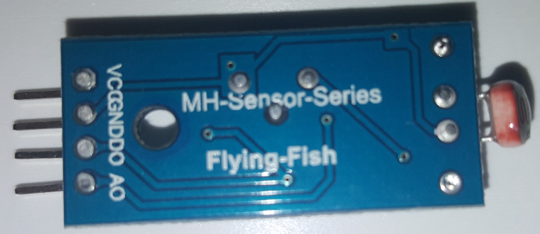
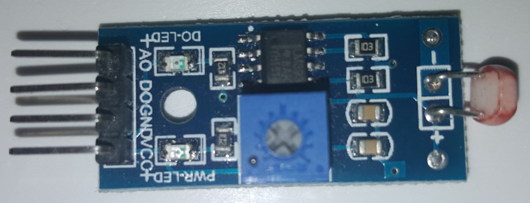
Thanks again!!@BeniK Try this simple code change:
change this line:
int16_t lightLevel = analogRead(LIGHT_LEVEL_PIN)/10.23;to this:
int16_t lightLevel = 100-(analogRead(LIGHT_LEVEL_PIN)/10.23);I will explain this change so you can understand it. The analogRead
analogRead(LIGHT_LEVEL_PIN)will return a value in the range of 0 to 1023. by dividing that by10.23, that will give you a value from 0 to 100, the percentage of light. Because you are getting inverted values, subtracting the value read by 100 will invert it. So you could change the following line from 90 back to 10:if (lightLevel < 90 && motion && relay == RELAY_OFF) { if (lightLevel < 10 && motion && relay == RELAY_OFF) {because now that you are subtracting the value from 100, 100 - 90 = 10, and all should be good.
Hope that makes sense.
Vera Plus running UI7 with MySensors, Sonoffs and 1-Wire devices
Visit my website for more Bits, Bytes and Ramblings from me: http://dan.bemowski.info/ -
@BeniK Try this simple code change:
change this line:
int16_t lightLevel = analogRead(LIGHT_LEVEL_PIN)/10.23;to this:
int16_t lightLevel = 100-(analogRead(LIGHT_LEVEL_PIN)/10.23);I will explain this change so you can understand it. The analogRead
analogRead(LIGHT_LEVEL_PIN)will return a value in the range of 0 to 1023. by dividing that by10.23, that will give you a value from 0 to 100, the percentage of light. Because you are getting inverted values, subtracting the value read by 100 will invert it. So you could change the following line from 90 back to 10:if (lightLevel < 90 && motion && relay == RELAY_OFF) { if (lightLevel < 10 && motion && relay == RELAY_OFF) {because now that you are subtracting the value from 100, 100 - 90 = 10, and all should be good.
Hope that makes sense.
Hello! It looks like you're interested in this conversation, but you don't have an account yet.
Getting fed up of having to scroll through the same posts each visit? When you register for an account, you'll always come back to exactly where you were before, and choose to be notified of new replies (either via email, or push notification). You'll also be able to save bookmarks and upvote posts to show your appreciation to other community members.
With your input, this post could be even better 💗
Register Login