Cannot get RFM69HW connection between ESP8266GW and Pro Mini Sensor
-
Ok, I have quoted that line for completeness. No change. I have also set
MY_SIGNING_SIMPLE_PASSWDon both nodes to try to rule out issues with encryption:These are my radio related precompiler statements right now:
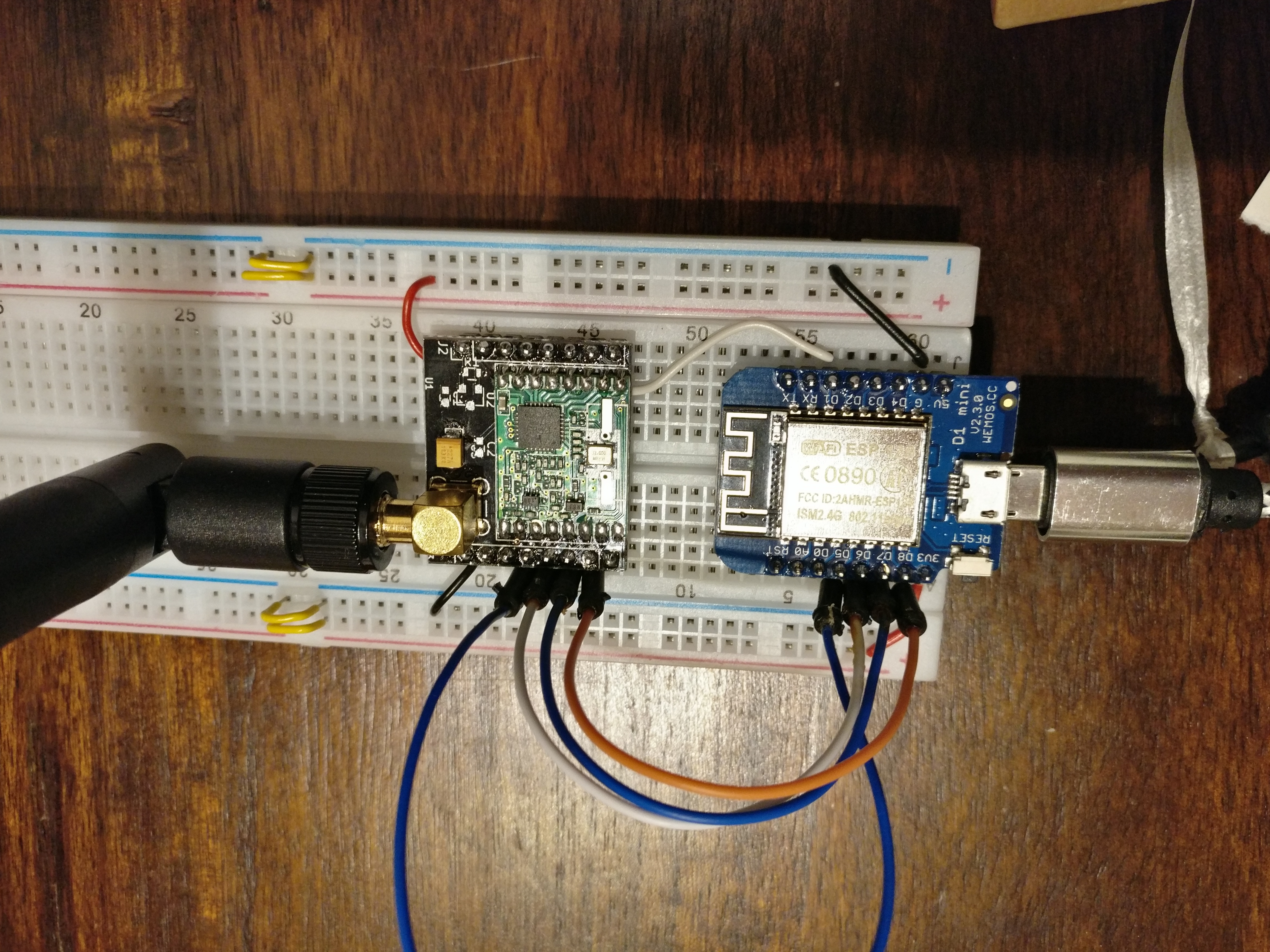
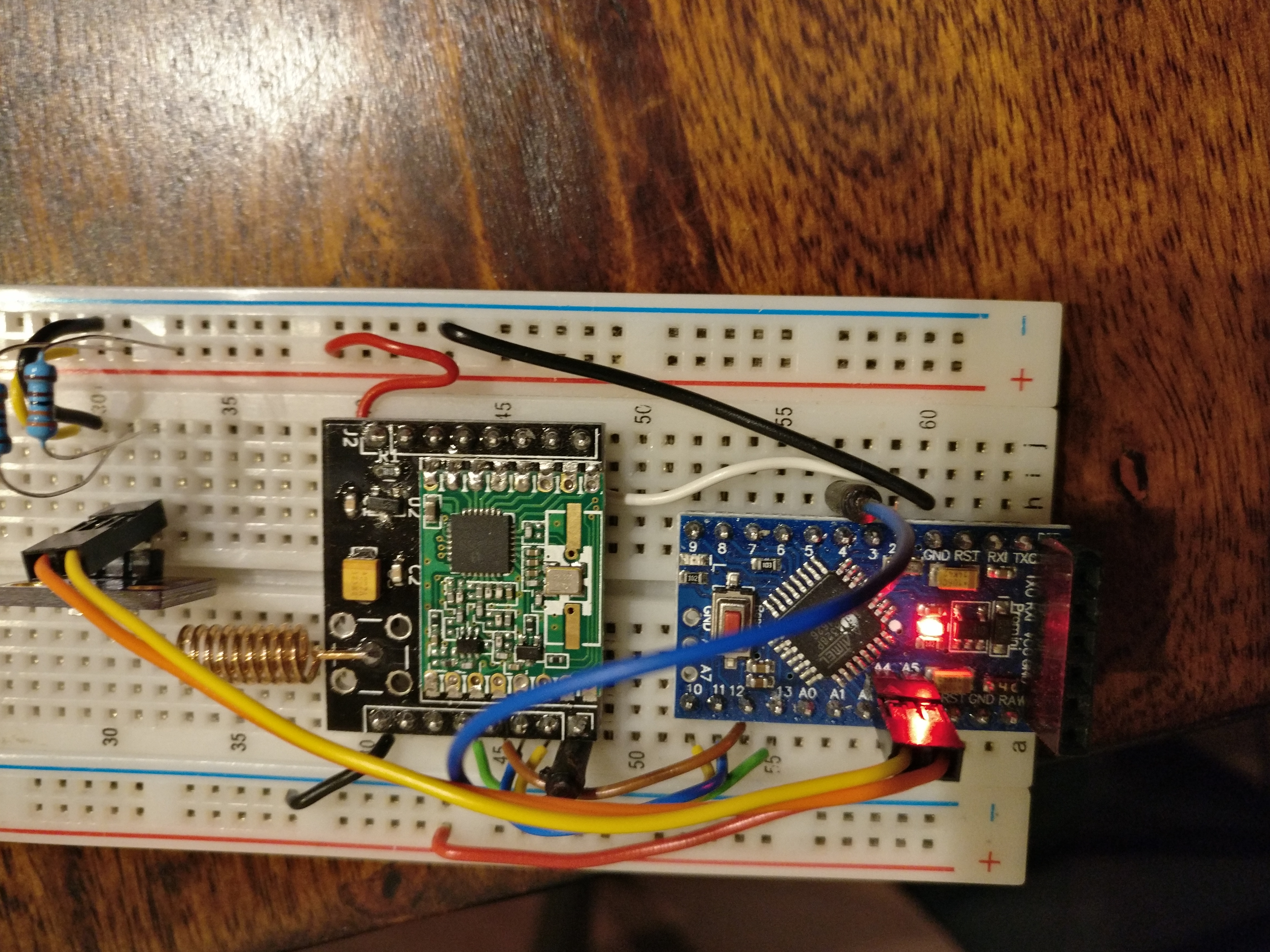
#define MY_RADIO_RFM69 #define MY_RFM69_FREQUENCY (RFM69_868MHZ) #if defined ARDUINO_ARCH_ESP8266 #define MY_RFM69_IRQ_PIN D1 #define MY_RFM69_CS_PIN D8 #elif defined ARDUINO_ARCH_AVR #define MY_RFM69_IRQ_PIN 2 #define MY_RFM69_CS_PIN 10 #endif #define MY_IS_RFM69HW #define MY_RFM69_NETWORKID (83) #define MY_SIGNING_SIMPLE_PASSWD "MyInsecurePassword" //#define MY_RFM69_MAX_POWER_LEVEL_DBM (10u) //#define MY_RFM69_ENABLE_ENCRYPTION //#define MY_RFM69_SPI_SPEED (800000ul) -
Ok, I have quoted that line for completeness. No change. I have also set
MY_SIGNING_SIMPLE_PASSWDon both nodes to try to rule out issues with encryption:These are my radio related precompiler statements right now:
#define MY_RADIO_RFM69 #define MY_RFM69_FREQUENCY (RFM69_868MHZ) #if defined ARDUINO_ARCH_ESP8266 #define MY_RFM69_IRQ_PIN D1 #define MY_RFM69_CS_PIN D8 #elif defined ARDUINO_ARCH_AVR #define MY_RFM69_IRQ_PIN 2 #define MY_RFM69_CS_PIN 10 #endif #define MY_IS_RFM69HW #define MY_RFM69_NETWORKID (83) #define MY_SIGNING_SIMPLE_PASSWD "MyInsecurePassword" //#define MY_RFM69_MAX_POWER_LEVEL_DBM (10u) //#define MY_RFM69_ENABLE_ENCRYPTION //#define MY_RFM69_SPI_SPEED (800000ul) -
@elcaron looked like you had encryption disabled previously, so I don't think any security feature is the cause of these issues. Unless you had it defined mysensors.h by accident.
@anticimex Didn't expect that either, but better safe than sorry.
-
@anticimex Didn't expect that either, but better safe than sorry.
-
For further testing, I have set up two Pro Mini now. With these, I get some communication.
SerialGateway:
0;255;3;0;9;0 MCO:BGN:INIT GW,CP=RRNGA---,VER=2.2.0
0;255;3;0;9;4 TSM:INIT
0;255;3;0;9;6 TSF:WUR:MS=0
0;255;3;0;9;10 TSM:INIT:TSP OK
0;255;3;0;9;14 TSM:INIT:GW MODE
0;255;3;0;9;16 TSM:READY:ID=0,PAR=0,DIS=0
0;255;3;0;9;22 MCO:REG:NOT NEEDED
0;255;3;0;14;Gateway startup complete.
0;255;0;0;18;2.2.0
0;255;3;0;9;28 MCO:BGN:STP
0;255;3;0;9;34 MCO:BGN:INIT OK,TSP=1
0;255;3;0;9;3753 TSF:MSG:READ,255-255-255,s=255,c=3,t=7,pt=0,l=0,sg=0:
0;255;3;0;9;3760 TSF:MSG:BC
0;255;3;0;9;3764 TSF:MSG:FPAR REQ,ID=255
0;255;3;0;9;3768 TSF:CKU:OK,FCTRL
0;255;3;0;9;3770 TSF:MSG:GWL OK
0;255;3;0;9;5695 TSF:MSG:SEND,0-0-255-255,s=255,c=3,t=8,pt=1,l=1,sg=0,ft=0,st=OK:0
0;255;3;0;9;6993 TSF:MSG:READ,255-255-0,s=192,c=3,t=3,pt=0,l=0,sg=0:
255;192;3;0;3;
0;255;3;0;9;9218 TSF:MSG:READ,255-255-0,s=161,c=3,t=3,pt=0,l=0,sg=0:
255;161;3;0;3;
0;255;3;0;9;11239 TSF:MSG:READ,255-255-0,s=79,c=3,t=3,pt=0,l=0,sg=0:
255;79;3;0;3;
0;255;3;0;9;13258 TSF:MSG:READ,255-255-0,s=49,c=3,t=3,pt=0,l=0,sg=0:
255;49;3;0;3;
Client:
16 MCO:BGN:INIT NODE,CP=RRNNA---,VER=2.2.0
26 TSM:INIT
28 TSF:WUR:MS=0
30 TSM:INIT:TSP OK
32 TSM:FPAR
1253 TSF:MSG:SEND,255-255-255-255,s=255,c=3,t=7,pt=0,l=0,sg=0,ft=0,st=OK:
1374 TSF:MSG:READ,0-0-255,s=255,c=3,t=8,pt=1,l=1,sg=0:0
1380 TSF:MSG:FPAR OK,ID=0,D=1
1576 TSF:MSG:READ,0-0-255,s=255,c=3,t=8,pt=1,l=1,sg=0:0
1779 TSF:MSG:READ,0-0-255,s=255,c=3,t=8,pt=1,l=1,sg=0:0
3262 TSM:FPAR:OK
3262 TSM:ID
3264 TSM:ID:REQ
3274 TSF:MSG:SEND,255-255-0-0,s=192,c=3,t=3,pt=0,l=0,sg=0,ft=0,st=OK:
5281 TSM:ID
5281 TSM:ID:REQ
5494 TSF:MSG:SEND,255-255-0-0,s=161,c=3,t=3,pt=0,l=0,sg=0,ft=0,st=OK:
7503 TSM:ID
7503 TSM:ID:REQ
7514 TSF:MSG:SEND,255-255-0-0,s=79,c=3,t=3,pt=0,l=0,sg=0,ft=0,st=OK:
9521 TSM:ID
9521 TSM:ID:REQ
9531 TSF:MSG:SEND,255-255-0-0,s=49,c=3,t=3,pt=0,l=0,sg=0,ft=0,st=OK:
11538 !TSM:ID:FAIL
11540 TSM:FAIL:CNT=1
11542 TSM:FAIL:DIS
11544 TSF:TDI:TSL
It looks like they exchange packages about the parent, but the gateway never answers the id request for some reason.
I have quoted all lines regarding inclusion mode in the gateway sketch.
Is this because no controller is configured?Interestingly, falshed as a node, the ESP8266 now also shows up on the gateway, with the same issues.
-
Exactly. If no controller is configured, nobody assigns a node id, so you need to define it yourself.
-
I asked you earlier if you set a NODE ID, if not you have to add
#define MY_NODE_ID 1
before the include mysensors.h in your node sketch
-
Ok, I have finally identified the issue.
I did some more testing with the switched roles, ESP8266 as (light) sensor, Pro Mini as serial gateway, hardcoded MY_NODE_ID. According to the logs, the ESP sends the parent quest, the Pro Mini answers, but never gets an ACK. The ESP does not report any answer. Ergo, the interrupt doesn't work.
So I scoped it, electrically, everything was fine. I tried D2 instead of D1, no change. Then I remembered that the default in the code was GPIO2, which is D4. This is a really stupid choice, because if you connect it like that, the ESP will not boot. GPIO2 needs to be pulled up during boot, and DIO0 from the RFM69 pulls it down. What works though is to first boot, then connect the cable.
Lo and behold - everything suddenly worked. So either I am the idiot and#define MY_RFM69_IRQ_PIN D1is not how you set the interrupt, or whoever thought that it was clever to default the interrupt to a pin that prevents booting also decided to ignore the configured value ...I'll dig into the code to find out, but of course wouldn't mind if anybody who knows the code better would be faster :)
Will file an issue or pull request if I find something. -
Quick update: Setting
#define MY_RFM69_IRQ_NUM 5(D1=GPIO5, the ESP has interrupts on (almost) all GPIO pins and the interrupt number equals the pin number) - that is, skipping the digitalPinToInterrupt() function - seems to work. That should pretty much localize the problem. -
Ok, I have finally identified the issue.
I did some more testing with the switched roles, ESP8266 as (light) sensor, Pro Mini as serial gateway, hardcoded MY_NODE_ID. According to the logs, the ESP sends the parent quest, the Pro Mini answers, but never gets an ACK. The ESP does not report any answer. Ergo, the interrupt doesn't work.
So I scoped it, electrically, everything was fine. I tried D2 instead of D1, no change. Then I remembered that the default in the code was GPIO2, which is D4. This is a really stupid choice, because if you connect it like that, the ESP will not boot. GPIO2 needs to be pulled up during boot, and DIO0 from the RFM69 pulls it down. What works though is to first boot, then connect the cable.
Lo and behold - everything suddenly worked. So either I am the idiot and#define MY_RFM69_IRQ_PIN D1is not how you set the interrupt, or whoever thought that it was clever to default the interrupt to a pin that prevents booting also decided to ignore the configured value ...I'll dig into the code to find out, but of course wouldn't mind if anybody who knows the code better would be faster :)
Will file an issue or pull request if I find something. -
@elcaron said in Cannot get RFM69HW connection between ESP8266GW and Pro Mini Sensor:
MY_RFM69_IRQ_PIN
So both MUST be defined? I thought NUM was prety much an override, since it can be programmatically derived from the pin. Undfortunaely, it does not seem to be documented.
-
Ok, I see ...
#define DEFAULT_RFM69_IRQ_NUM digitalPinToInterrupt(DEFAULT_RFM69_IRQ_PIN)So it indeed has to be set separately. I don' really see why this isn't set to
#define DEFAULT_RFM69_IRQ_NUM digitalPinToInterrupt(MY_RFM69_IRQ_PIN)MyConfig.h is included before, so tha should work.
-
I don't know why the code is written the way it is. When I verified the rfm69 wiring and wrote the instructions, I decided to not use the default IRQ pin, since it would interfere with boot (as you also have identified). That's why I added the define instructions to set both MY_RF69_IRQ_PIN and MY_RF69_IRQ_NUM.
I am not familiar with the rfm69 driver code, but I think what you suggest should work. You are very welcome to create a pull request. If someone has any objections, they can always make their case during the code review.
-
@mfalkvidd said in Cannot get RFM69HW connection between ESP8266GW and Pro Mini Sensor:
When I verified the rfm69 wiring and wrote the instructions, I decided to not use the default IRQ pin
Maybe note this in the instructions? This cost me 1 year (in which I did not touch the stuff after i didn't work immediately) and a weekend of checking wireing and so on (because with a missing IRQ on the gateway, it looks like nothing is working, while the issue is quite easy to find on a node).
Ok, PR is filed, I also fixed it for the RFM95, which had the same issue.
-
@elcaron could you describe the type of note you think you would have noticed?
Great work on the PR.
@mfalkvidd Maybe a "* Different from code default and examples"?
You do not really expect that you have to change defaults when you get a wiring guide from the official site associated with the code, especially when running an example that is explicitly for the platform (the ESP8266 gateway sketch).In hindsight, this was probably stupid, but I didn't even look at the defines below the table, because I thought I was running a working example specifically for the ESP8266 and only needed to find the right pins.
-
@mfalkvidd Maybe a "* Different from code default and examples"?
You do not really expect that you have to change defaults when you get a wiring guide from the official site associated with the code, especially when running an example that is explicitly for the platform (the ESP8266 gateway sketch).In hindsight, this was probably stupid, but I didn't even look at the defines below the table, because I thought I was running a working example specifically for the ESP8266 and only needed to find the right pins.
Hello! It looks like you're interested in this conversation, but you don't have an account yet.
Getting fed up of having to scroll through the same posts each visit? When you register for an account, you'll always come back to exactly where you were before, and choose to be notified of new replies (either via email, or push notification). You'll also be able to save bookmarks and upvote posts to show your appreciation to other community members.
With your input, this post could be even better 💗
Register Login