LoRa Nodes
-
Made this prototype LoRa PIR sensor node:
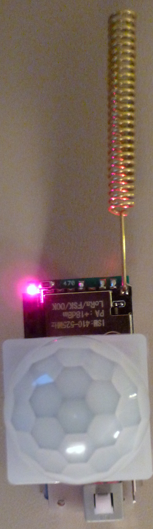
Uses an AM612. Works very nicely. Presently powered by two AAA batteries, but I'll be expanding that to at least 3x AAA batteries to maintain adequate minimum voltage for operating the AM612.Except for the antenna, the whole thing fits within the footprint of 2xAAA batteries.
-
Even though a stackable design affords a lot of configuration options, it can get rather tall in a hurry!
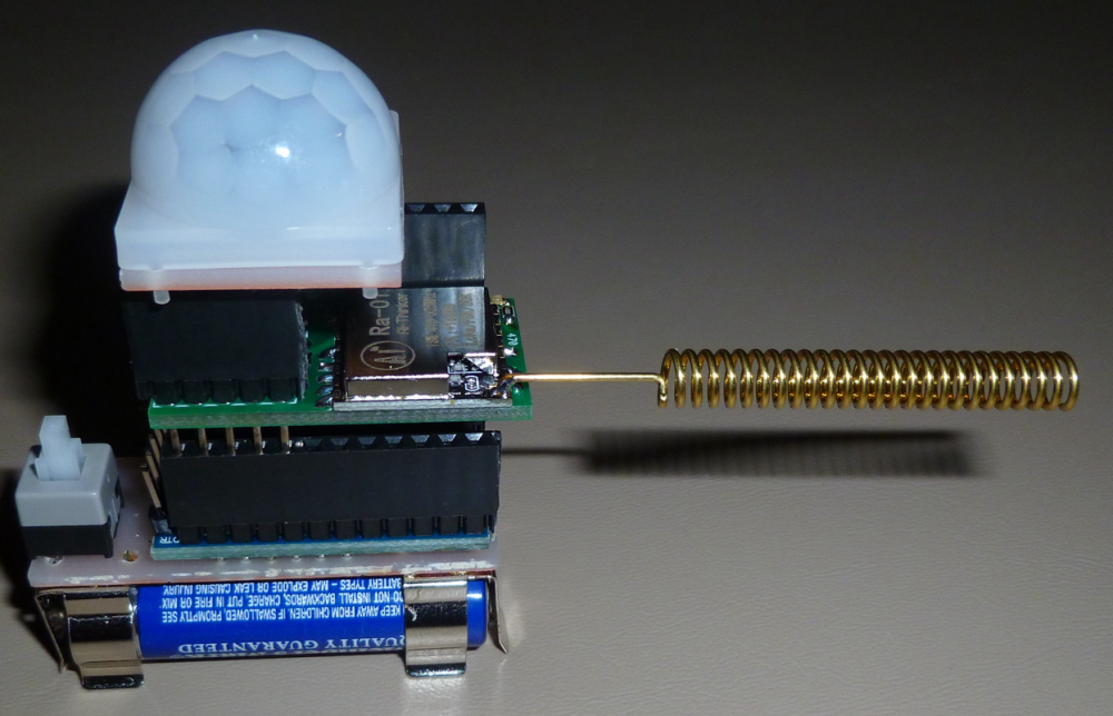
Of course, you can address that by soldering the boards directly to one another, but doing so gets you a static configuration that you can't then pull apart anymore to change the configuration. In that case, maybe you're better off putting everything onto a single PCB in the first place.So, as you can probably tell, I'm mulling this over.
-
Even though a stackable design affords a lot of configuration options, it can get rather tall in a hurry!
Of course, you can address that by soldering the boards directly to one another, but doing so gets you a static configuration that you can't then pull apart anymore to change the configuration. In that case, maybe you're better off putting everything onto a single PCB in the first place.So, as you can probably tell, I'm mulling this over.
-
Here it is with the four boards soldered directly together:
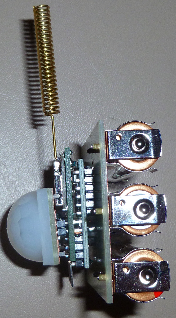
It works well, but I've since recast it as a single board with the same small 3xAA footprint. So, I don't think I'm a believer anymore in the stacked approach, unless maybe it's just one board stacked on another.I may continue stacking for prototypes though, until I can get my CNC to reliably churn out PCB's at fine pitch. Maybe that will be possible after the upgrades I have planned....
-
With the ATmega328p and LoRa radio sleeping, but the LDO and AM612 still working to find motion, I measure the current drain at 19.7uA. That's a little higher than I was expecting, but not by a huge amount, as the AM612 by itself consumes 14-16uA. So, adding about 1uA for the LoRa radio and about 1uA quiescent for the LDO and about 150nA for the ATmega328p, that gets us to around 18uA as the theoretical expectation for current drain. I suspect the 10K pull-up resistor on the DTR may add to the drain as well.
In any case, if I were to use 3x Energizer Lithium AA batteries, which have 3500mah of capacity, that would give me around 20 years of sleep current, which is good enough for me. :)
-
I can reduce the transmit power to 5db, which is as low as it goes with the PA turned on, but which still seems more than enough to give me whole home coverage without any skips. That translates to about 30ma Tx current (as measured on my o-scope). Doing that and using the radiohead library to transmit "Hello World" at the default settings takes about 45ms (again, as measured on my o-scope).
Now, that may sound like a lot of current and a lot of time, but not really. Transmitting that once every 5 minutes yields an average current consumption of 4.5uA.
So, adding that to the sleep current of 20uA (rounding up), yields an average current drain of 24.5uA.
So, again, using 3x Energizer Lithium AA batteries (3500mah), this device should be able to operate for 16.3 years! Now, of course, it will be less than that, because there will be additional messages transmitted whenever motion is detected, but you can make some assumptions about how often that is.
For instance, assuming an average of 12 motion detection alerts per hour, the average constant current drain rises to 29uA. That would equate to 13.8 years of operation. Not bad! :) -
I tried running the MySensors LoRa motion sensor code to connect with the MySensors LoRa serial gateway code:
/**
 * The MySensors Arduino library handles the wireless radio link and protocol
 * between your home built sensors/actuators and HA controller of choice.
 * The sensors forms a self healing radio network with optional repeaters. Each
 * repeater and gateway builds a routing tables in EEPROM which keeps track of the
 * network topology allowing messages to be routed to nodes.
 *
 * Created by Henrik Ekblad <henrik.ekblad@mysensors.org>
 * Copyright (C) 2013-2015 Sensnology AB
 * Full contributor list: https://github.com/mysensors/Arduino/graphs/contributors
 *
 * Documentation: http://www.mysensors.org
 * Support Forum: http://forum.mysensors.org
 *
 * This program is free software; you can redistribute it and/or
 * modify it under the terms of the GNU General Public License
 * version 2 as published by the Free Software Foundation.
 *
 *******************************
 *
 * REVISION HISTORY
 * Version 1.0 - Henrik Ekblad
 *
 * DESCRIPTION
 * Motion Sensor example using HC-SR501
 * http://www.mysensors.org/build/motion
 *
 */

// Enable debug prints
// #define MY_DEBUG

// Enable and select radio type attached
//#define MY_RADIO_NRF24
//#define MY_RADIO_NRF5_ESB
//#define MY_RADIO_RFM69
#define MY_RADIO_RFM95

#include <MySensors.h>

uint32_t SLEEP_TIME = 120000; // Sleep time between reports (in milliseconds)
#define DIGITAL_INPUT_SENSOR 3   // The digital input you attached your motion sensor.  (Only 2 and 3 generates interrupt!)
#define CHILD_ID 1   // Id of the sensor child

// Initialize motion message
MyMessage msg(CHILD_ID, V_TRIPPED);

void setup()
{
	pinMode(DIGITAL_INPUT_SENSOR, INPUT);      // sets the motion sensor digital pin as input
 Serial.println("Starting....");
}

void presentation()
{
	// Send the sketch version information to the gateway and Controller
	sendSketchInfo("Motion Sensor", "1.0");

	// Register all sensors to gw (they will be created as child devices)
	present(CHILD_ID, S_MOTION);
}

void loop()
{
	// Read digital motion value
	bool tripped = digitalRead(DIGITAL_INPUT_SENSOR) == HIGH;

	Serial.println(tripped);
	send(msg.set(tripped?"1":"0"));  // Send tripped value to gw

	// Sleep until interrupt comes in on motion sensor. Send update every two minute.
	sleep(digitalPinToInterrupt(DIGITAL_INPUT_SENSOR), CHANGE, SLEEP_TIME);
}
but it just seems to hang. It never even gets to the setup loop, where I had enterd a println to say, "Starting..."
On the node, the serial output is:
dd⸮d⸮⸮⸮⸮ccÄ⸮f⸮d⸮cÄc⸮⸮c⸮___  ___  _ __ ___
| |\/| | | | \___ \ /⸮
 __  __       ____
|  \/  |_   _/ ___|  ___ _ __  ___  ___  _ __ ___
| |\/| | | | \___ \ / _ \ `_ \/ __|/ _ \| `__/ __|
| |  | | |_| |___| |  __/ | | \__ \  _  | |  \__ \
|_|  |_|\__, |____/ \___|_| |_|___/\___/|_|  |___/
        |___/                      2.3.0-alpha
and on the gateway, the serial output is:
Console
0;255;3;0;9;0 MCO:BGN:INIT GW,CP=RLNGA---,VER=2.2.0-rc.2
0;255;3;0;9;14 TSM:INIT
0;255;3;0;9;20 TSF:WUR:MS=0
0;255;3;0;9;38 TSM:INIT:TSP OK
0;255;3;0;9;47 TSM:INIT:GW MODE
0;255;3;0;9;55 TSM:READY:ID=0,PAR=0,DIS=0
0;255;3;0;9;67 MCO:REG:NOT NEEDED
0;255;3;0;14;Gateway startup complete.
0;255;0;0;18;2.2.0-rc.2
0;255;3;0;9;79 MCO:BGN:STP
0;255;3;0;9;100 MCO:BGN:INIT OK,TSP=1
However, on the same hardware, RadioHead works fine. Go figure.
-
Here's the single PCB version of the LoRa motion detector:
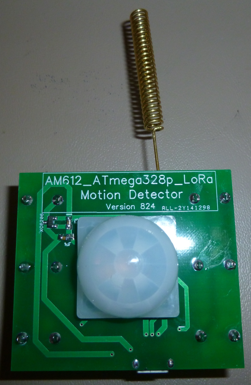
It works as expected. The entire board is roughly the size footprint as the 3x AA batteries that are a part of it. Thanks to @NCA78, it's using an XC6206 LDO.I just received a 3D printer kit today. I suppose the next step will be to print a 3D case for it. Ideally I'd like to make it waterproof/moistureproof so that it can also work outdoors.
-
I can reduce the transmit power to 5db, which is as low as it goes with the PA turned on, but which still seems more than enough to give me whole home coverage without any skips. That translates to about 30ma Tx current (as measured on my o-scope). Doing that and using the radiohead library to transmit "Hello World" at the default settings takes about 45ms (again, as measured on my o-scope).
Now, that may sound like a lot of current and a lot of time, but not really. Transmitting that once every 5 minutes yields an average current consumption of 4.5uA.
So, adding that to the sleep current of 20uA (rounding up), yields an average current drain of 24.5uA.
So, again, using 3x Energizer Lithium AA batteries (3500mah), this device should be able to operate for 16.3 years! Now, of course, it will be less than that, because there will be additional messages transmitted whenever motion is detected, but you can make some assumptions about how often that is.
For instance, assuming an average of 12 motion detection alerts per hour, the average constant current drain rises to 29uA. That would equate to 13.8 years of operation. Not bad! :)@neverdie said in LoRa Nodes:
using the radiohead library to transmit "Hello World" at the default settings takes about 45ms (again, as measured on my o-scope).
The RadioHead default settings were:
Bw125Cr45Sf128 : Bw = 125 kHz, Cr = 4/5, Sf = 128chips/symbol, CRC on. Default medium range.Current register values are:
1: 80
6: 6C
7: 80
8: 0
9: 80
A: 9
B: 2B
C 0
D 11
E: 0
F: 0
10: 0
11: 0
12: 0
13: 0
14: 0
15: 0
16: 0
17: 0
18: 0
19: 0
1A: 0
1B: 0
1C : 0
1D : 72
1E: 74
1F: 64
20: 0
21: 8
22: 11
23: FF
24: 0
25: 0
26: 4
27: 0If I were to change that to Bw=500kHz and Sf=64chips/symbol, then I could reduce the Tx time to 6.2ms. And that would be as low as I could take it without reducing the data payload, which I'm fairly sure I can also do.
[Edit: A brute force reduction of the spreading factor to 64 seems to break the communication between the node and gateway, so for now I'm leaving the spreading factor at 128. ]
[Edit2: According to the datasheet a spreading factor of 64 is a special case that requires unique treatment.]
-
So, after increasing the bandwidth to 500Khz and reducing the data payload, the node now consumes 38ma for 13ms during its Tx to the gateway, which is 37% of the energy consumed in the earlier measurement above. I see that further improvements are possible, but I deem it good enough for now. :)
Hello! It looks like you're interested in this conversation, but you don't have an account yet.
Getting fed up of having to scroll through the same posts each visit? When you register for an account, you'll always come back to exactly where you were before, and choose to be notified of new replies (either via email, or push notification). You'll also be able to save bookmarks and upvote posts to show your appreciation to other community members.
With your input, this post could be even better 💗
Register Login