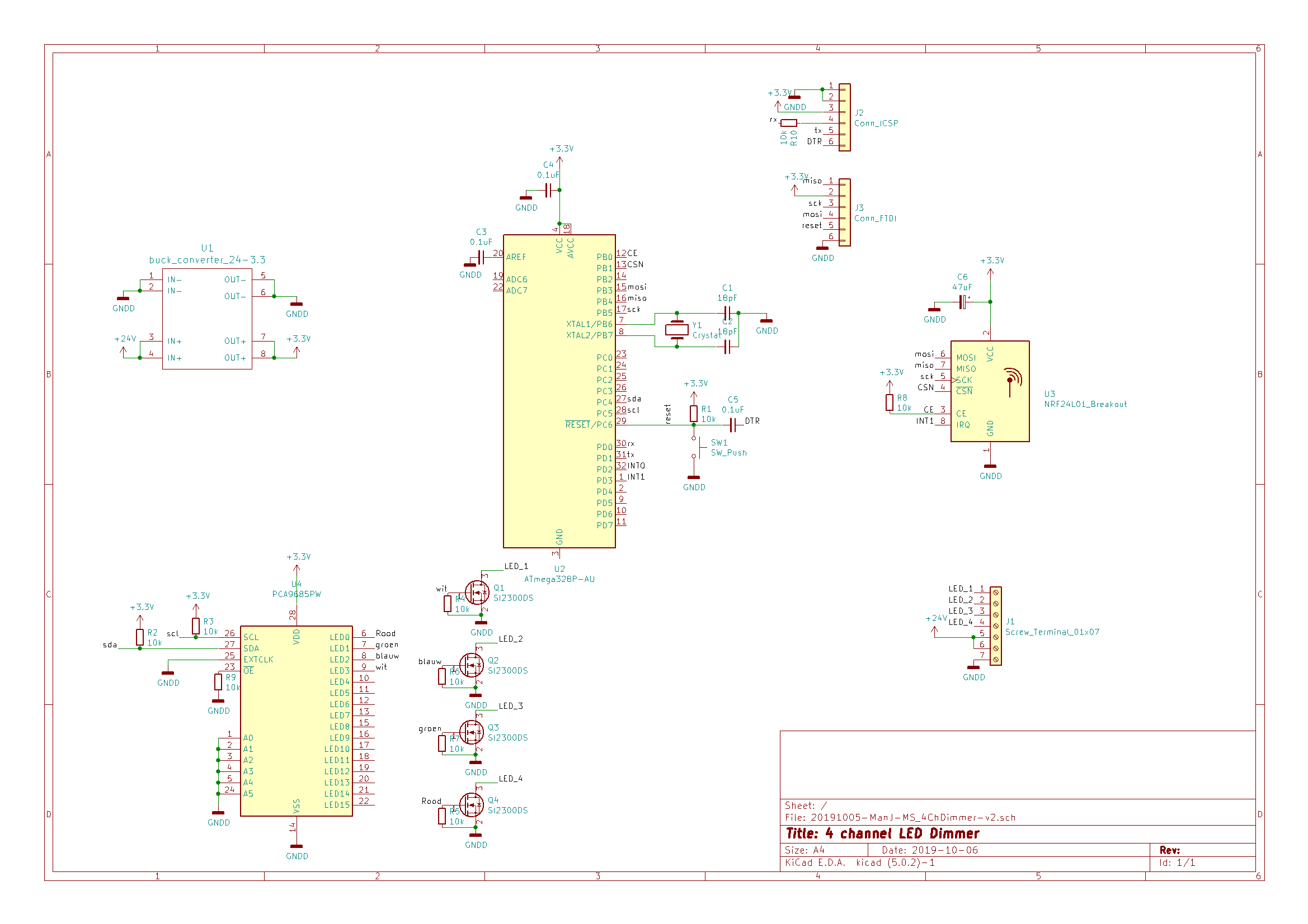
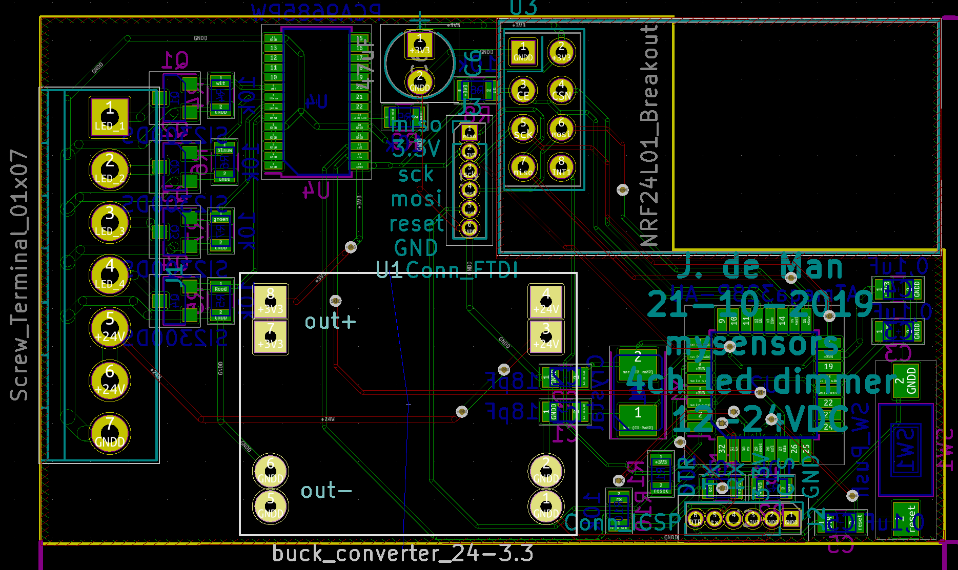
Please check my pcb design for 24V LED Dimmer
-
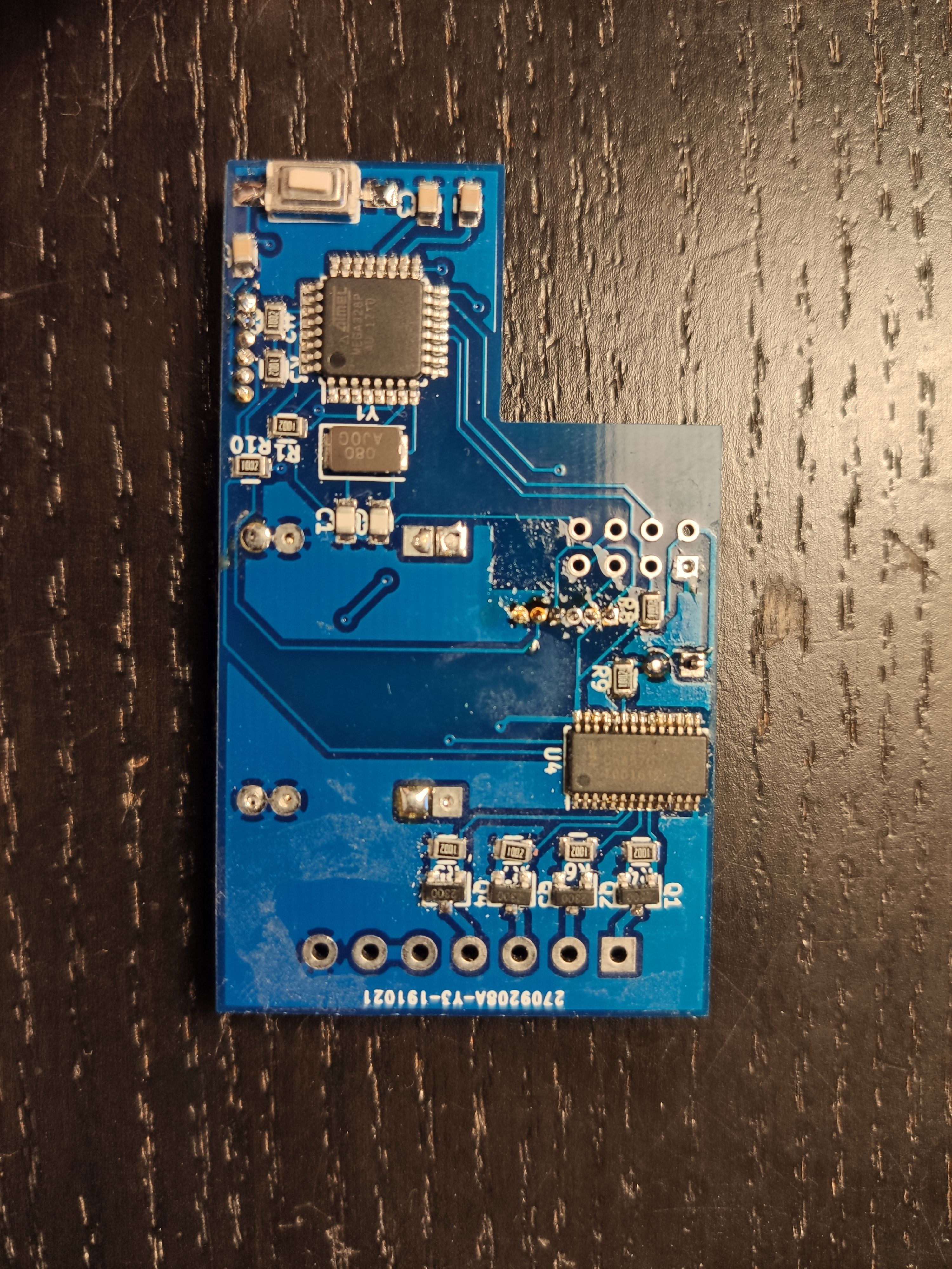
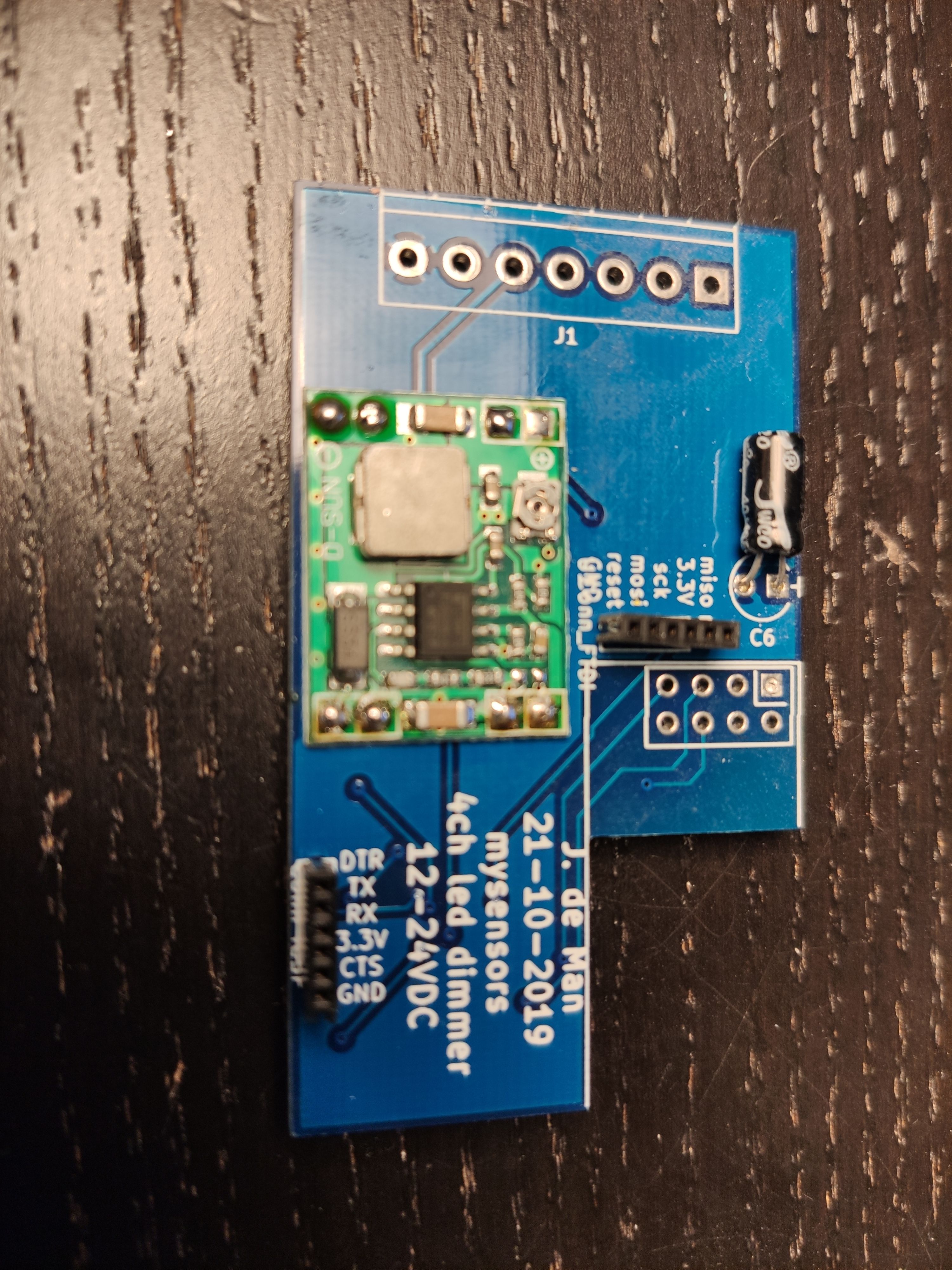
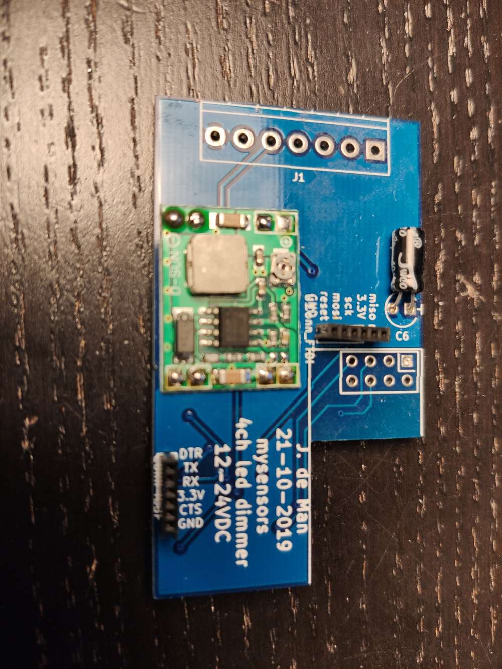
I just soldered my new pcb for a 24VDC led dimmer. However I can not load a bootloader. I checked the USBASP that I use, it is fully working.
I checked connections, I checked the orientation of the microcontroller. But I fear I just did something completely wrong. This is my first time to use the bare chip.

-
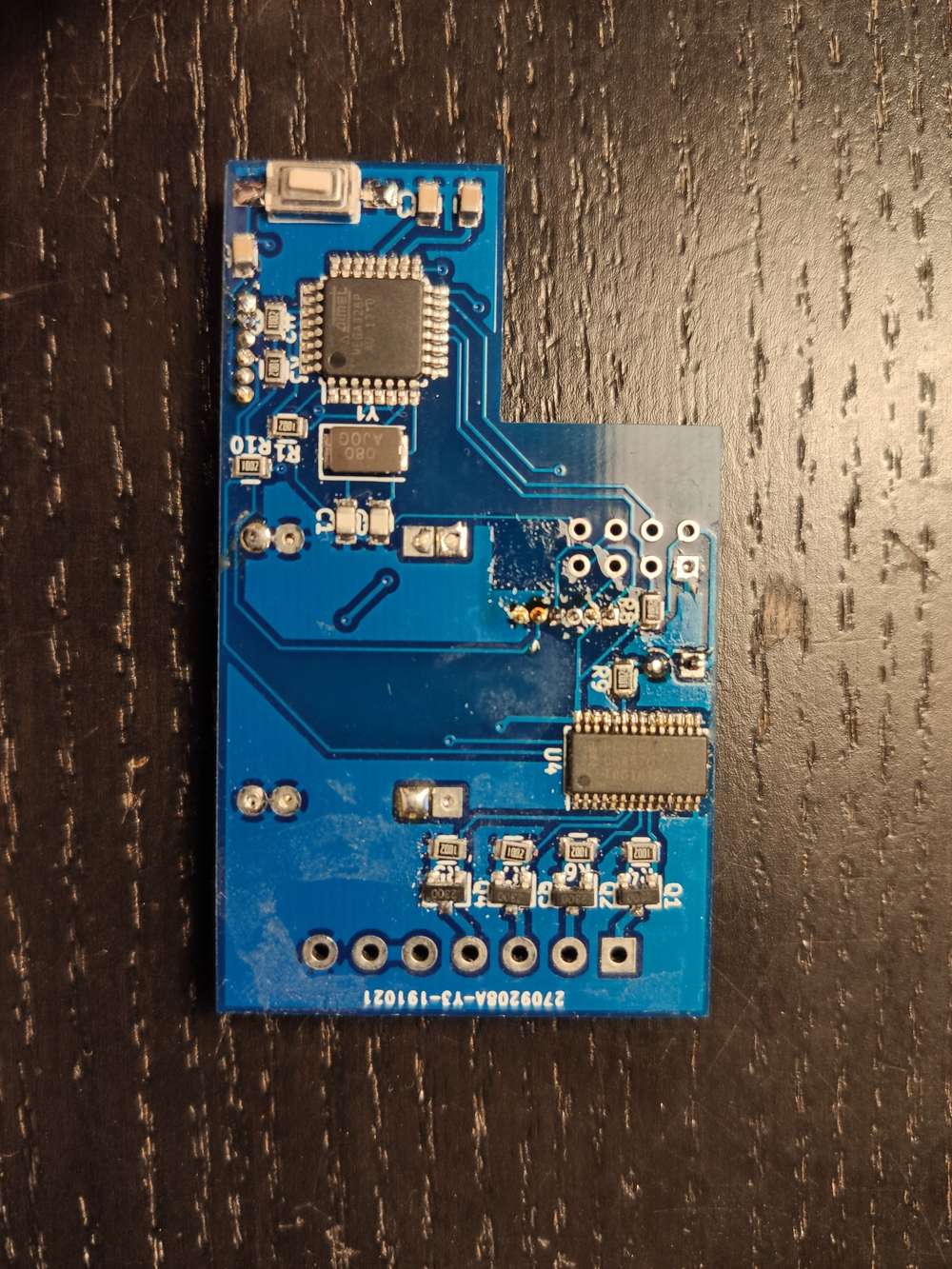
I found one problem. The ground of the atmega was never connected to the rest of the circuit. I solved this nou with a wire, but it has not fixed the problem.
I soldered all the smd parts in a oven. Could this be a problem for some parts?
I tried again. this time I did not connect the voltage converter. I used the power from the USBASP like I succesfully tested on a pro mini.
I used a different brand for the crystal.
Still nothing.
Edit 3:
16MHz crystal also no use -
Yes, I noticed now as well.... Annoying but I was looking at the labels of the pins more than everything else.
I found the problem. The bare chips that I have are fake.
I transplanted one from a pro mini and now it works. This took me way to many hours to find out. What a waist of time.
-
I had very often issues with programming bare chips if any other connection is on MOSI/MISO or let’s say on the SPI. I would suggest to check your chips on a breadboard on load the boot loader before using them in a circuit. In your case it looks like you connected your 2.4g Radio as well to the ISP which in my cases always interfered with programming. I solved that by using jumpers to isolate the AVR when programming. Hope this helps preventing you from throwing away chips which might work...
Good luck
@adfx Thanks for checking. I read once a blog/page about the use of multiple spi devices. It explained about the use of pull up resistors on the enable pin of every device you have on this bus for this specific problem. Just to be sure when I was testing it I did not connect the nrf24.
I added that resistor to this PCB. So far it's works with the MySbootloader and just burning the program with the USBASP. Even with the nrf connected.
I really believe that it was the chip itself. But I still have them waiting for a better test environment.
Hello! It looks like you're interested in this conversation, but you don't have an account yet.
Getting fed up of having to scroll through the same posts each visit? When you register for an account, you'll always come back to exactly where you were before, and choose to be notified of new replies (either via email, or push notification). You'll also be able to save bookmarks and upvote posts to show your appreciation to other community members.
With your input, this post could be even better 💗
Register Login