Multi-sensor home module (With batteries)
-
MULTI-SENSOR (With batteries)
This project consists of a module that manages different sensors for home use. The idea is to be able to mix and match different sensors, according to the requirements of each area of the house, using a single PCB design and a configurable sketch, making it easier to setup and maintain a sensor network.
Description
The sensor module is based on the MySensors library using an Arduino
 Mini Pro, which has a good number of interface pins, it has a small footprint and is suited for running on batteries.
The radio module for wireless communication is the NRF24L01.It supports the following sensors:
• Motion Sensor.
• 1 – 3 Door / Window sensors.
• Temperature and humidity sensor.
• Flame sensor.
• Light sensor.
• LUX Sensor (I2C).
• Smoke sensor.
• Gas sensor.
• CO sensor.
• 1 – 3 Moisture sensors.
• 1 – 3 Leak detectors.It also includes the features:
• Battery operation or battery backup
• Audible Alarm
• Reset / Test / Calibrate buttonHardware
The module is based on the Arduino
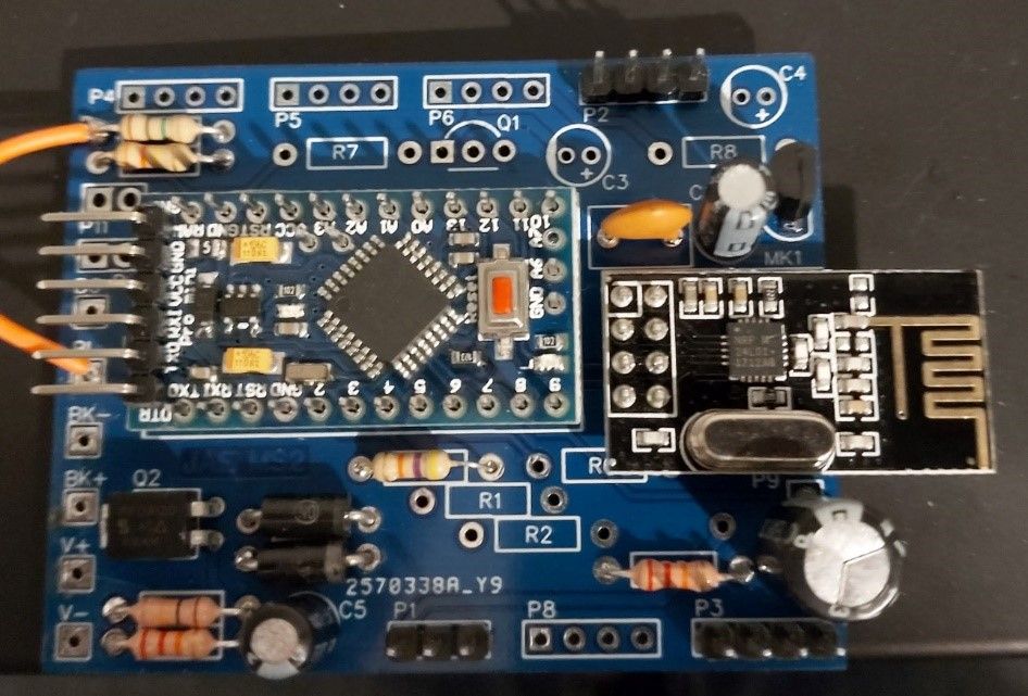
 Mini Pro and the NRF24L01 radio, using readily available sensor boards, connected through a PCB.
The sensor module can be powered using a small power supply, through batteries, or a combination of a power supply and rechargeable battery for backup.Schematic Diagram
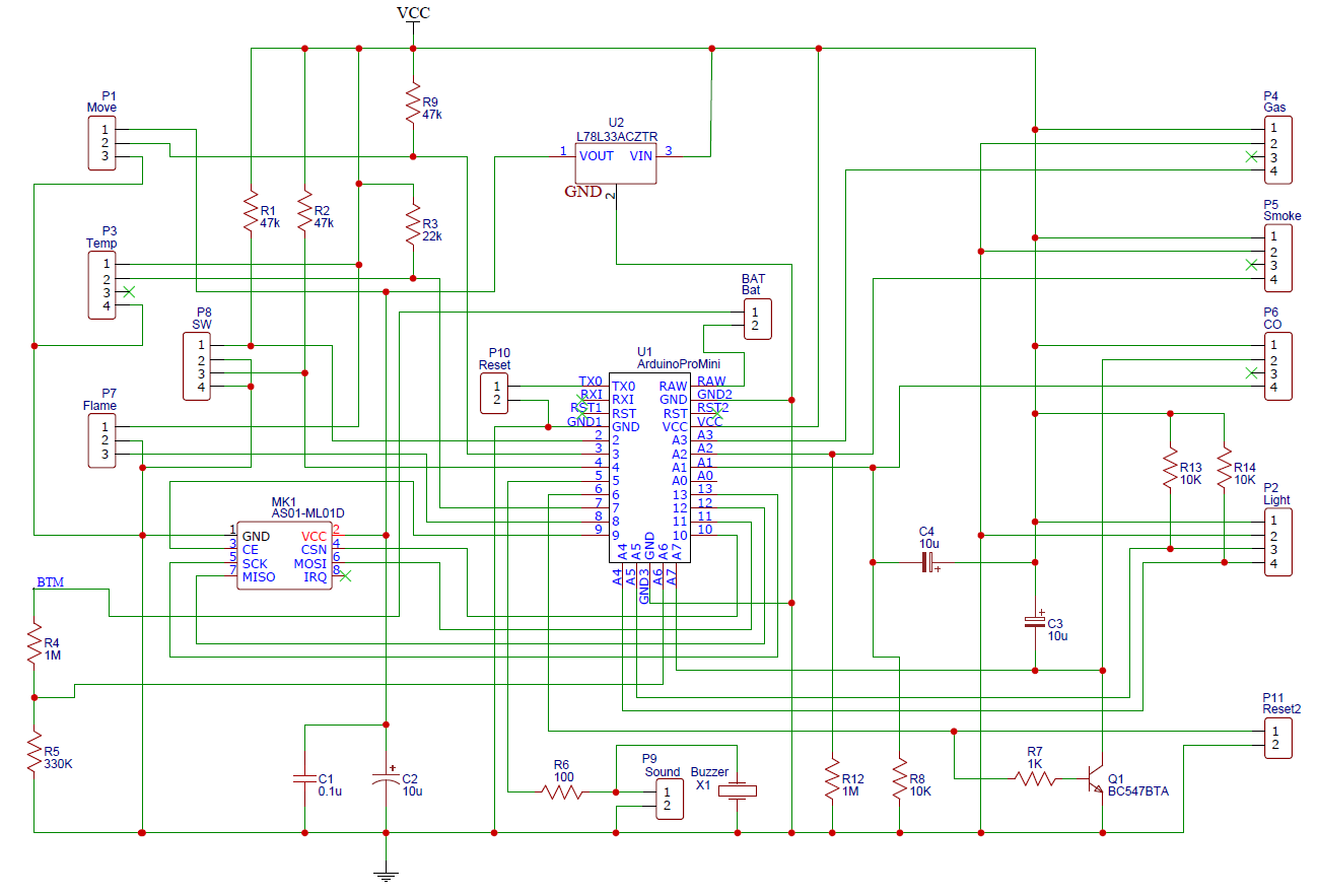
PCB
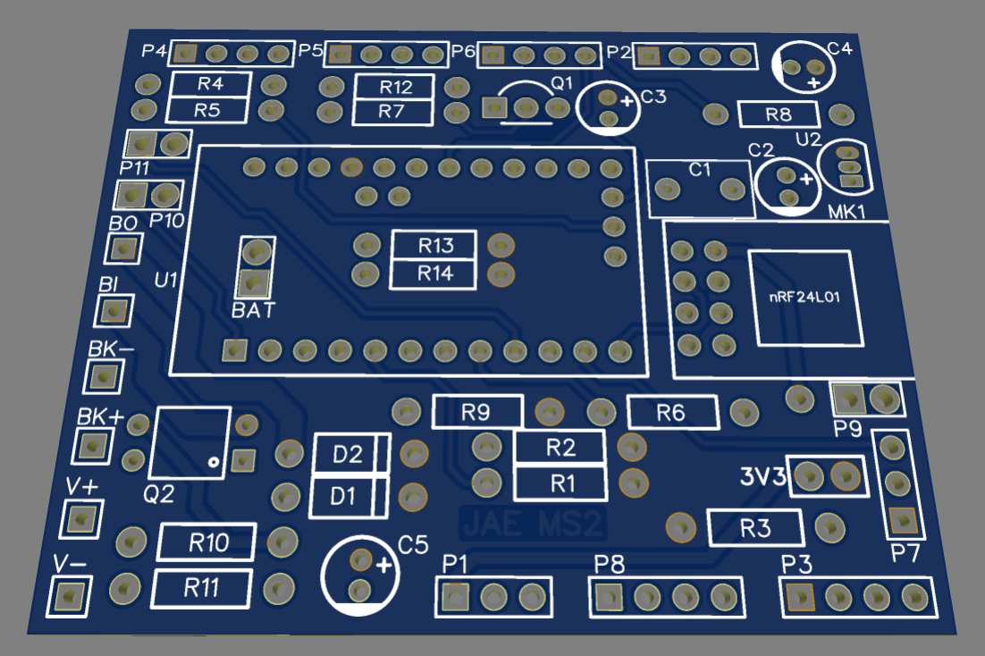
Link to PCBMicrocontroller
The module can be configured with a 5V or 3.3V Arduino Pro Mini microcontroller module.
In the case of battery operation, it is recommended to use the 3.3V microcontroller. In this case, all sensors must be rated to operate at 3.3V.
In the case of a 5V microcontroller you can use 5V and 3.3V sensors in combination.
The NRF24L01 radio module requires 3.3V, so a regulator (U2) for the radio (and the motion sensor) is included in the circuit, in case of using a 5V microcontroller.
If the controller is 3.3V, the U2 regulator is not required, but it is necessary to put a jumper between terminals 1 and 3 of U2.Sensors
Some of the sensors use the same pins in the microcontroller, so a combination of sensors can be chosen according to the following table:
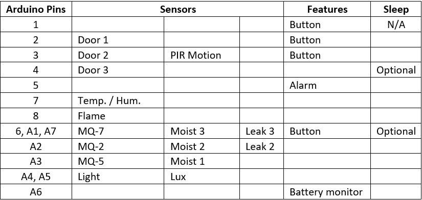
The sensors that require it, have been configured with external Pull Up resistors to improve energy consumption and to be able to operate with batteries.
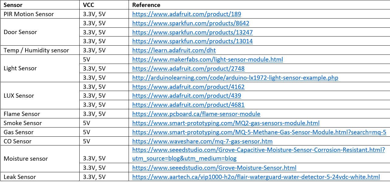
Wiring
a) Motion sensor
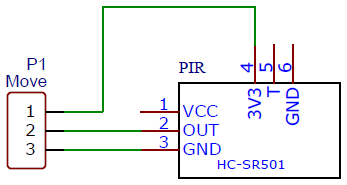
Install 47 KOhms resistor R9.
The motion sensor is connected to the 3.3V source, which is more efficient in power consumption. Consider the next articles for details on how to connect the PIR sensor:
https://screenzone.eu/modify-hc-sr501-pir-sensor-to-work-with-3-3v/
https://gndtovcc.home.blog/2020/04/23/modifying-cheap-pir-motion-sensor-to-work-at-3-3v/b) Door sensors 1 and 3
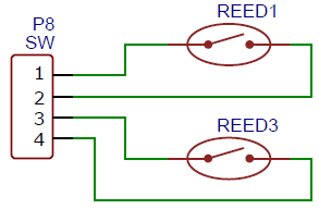
Install 47 KOhms resistors R1 (Door 1) and R2 (Door 2).c) Door sensor 2
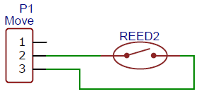
Install 47 KOhms resistor R9.d) Temperature / Humidity sensor
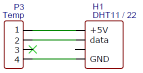
Install 22 KOhms resistor R3.e) Light sensor
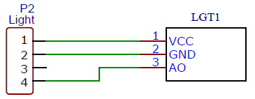
f) LUX Sensor
This sensor connects using two data pins with the I2C protocol. Any other I2C compatible sensor can be used instead or in parallel, but the sketch must be modified and the corresponding libraries installed.
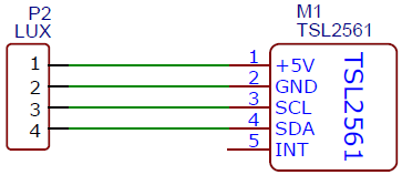
Install 10 KOhms resistors R13 and R14.g) Flame sensor
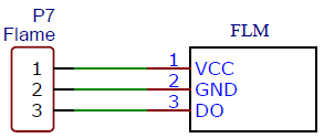
Air Quality Sensors
The module supports 3 air quality sensors. MQ-2, MQ-5 and MQ-7. It is possible to replace the MQ-2 and MQ-5 with others similar sensors to detect specific gases, but the curves for the calculation of PPMs must be adjusted in the sketch.
These MQ sensors have different sensitivities to different gases, however it is not possible to differentiate between one specific gas, for this reason the module has been equipped with a sensor for general air quality detection (MQ-2) and other more specific ones in order to have an accurate reading of the type of gas present, if required.
These sensors can consume up to 900mA, so it is not suitable for battery operation, so it is recommended to have a power supply with backup batteries, especially if using more than one sensor simultaneously.
For a simple, general use sensor and triggering an alarm, a single MQ-2 sensor is enough. If a more accurate reading of flammable gases is required, the MQ-5 can be used and MQ-7 can be used to detect Carbon Monoxide more accurately.
The MQ-2 is a general-purpose sensor that can detect:
• Smoke
• Liquefied Petroleum Gas (LPG)
• Natural Gas (CH4)
• Carbon Monoxide (CO)
The MQ-5 is sensor focused on flammable gases and can detect:
• Liquefied Petroleum Gas (LPG)
• Natural Gas (CH4)
The MQ-7 sensor is specific for Carbon Monoxide. This sensor requires the application of two voltage levels alternately, so it requires constant operation of the microprocessor, so if this sensor is activated, the sleep mode is deactivated.
The air quality sensors can be used to trigger an alarm or exclusively for monitoring.
When any of the air quality sensors is enabled in the module, the calibration button is automatically enabled. See below on the BUTTON and INTERRUPTIONS sections for more details.
If the alarm feature is enabled, it will be trigger if certain levels are reached in the monitored gases. The button is also used to reset / test the alarm.h) Smoke sensor
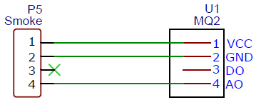
i) Gas sensor
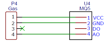
j) Carbon Monoxide sensor
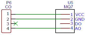
Install 1 KOhms resistor R7, 10 KOhms resistor R8, 10uF tantalum capacitors C3 and C4, and transistor Q1 (BC547B).Moisture / Leak Sensors
Moisture sensors are used to measure humidity in media such as soil, but can also be used as water leak detectors, setting a humidity threshold.
The type of sensors supported are:
• https://www.seeedstudio.com/Grove-Capacitive-Moisture-Sensor-Corrosion-Resistant.html?utm_source=blog&utm_medium=blog
• https://www.seeedstudio.com/Grove-Moisture-Sensor.html
For the humidity in the soil it is recommended to use the capacitive type, since they are more durable and do not release harmful residues that can affect the chemistry of the soil.
There are other types of sensors that are used specifically to detect leaks:
• https://www.aartech.ca/vip1000-h2o/flair-waterguard-water-detector-5-24vdc-white.html
These sensors require a Pull Up resistor. The module supports two of these sensors in positions 2 and 3.
Moisture sensors use the same analog inputs as gas sensors.
• Moisture 1 uses the same Analog Pin as the MQ-5 Air quality sensor.
• Moisture 2 uses the same Analog Pin as the MQ-2 Air quality sensor.
• Moisture 3 uses the same Analog Pin as the MQ-7 Air quality sensor.k) Moisture sensors 1 – 3
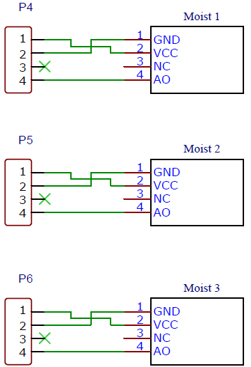
l) Water Leak Sensors
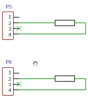
Install 1 MOhm resistors R12 and R8.Features
Alarm
The alarm is based on a simple piezoelectric transducer, which can produce sounds at an acceptable volume.
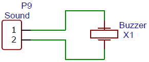
Install 100 Ohm resistors R6.Alarm Triggers
The alarm can be triggered by various gas measurements or moisture sensors.
• Flame On/Off (The threshold is calibrated in the sensor module)
• Smoke 300ppm
• LPG 300ppm
• Natural gas 300ppm
• CO 40ppm
• Leak/Flood 1 10%
• Leak/Flood 2 10%
• Leak/Flood 3 10%Button
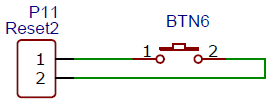
The button is used to Reset and Test the alarm, as well as to Calibrate the Air Quality sensors.
• Short press; Less than 3 seconds. Resets the alarm (it will stay off for at least 30 seconds; see ALARM_RETRIGGER in the sketch).
• Long press; 3-5 seconds. Starts an alarm test for 10 seconds (See ALARM_TEST in the sketch).
• Very long press; Longer than 6 seconds. Starts a calibration for the Air Quality sensors. The sensors need to be in clean air for the calibration to be effective.
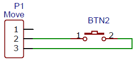
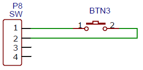
The button can be installed on pins 2 (default) or 3, depending on the other sensors present. If the button is installed in these positions, an interruption is assigned to the button and the microcontroller can enter sleep mode.
If these pins are not available, it can be installed on pin 6 or on pin 1. In these cases the sleep cycle is suspended and for pin 1 the debugging for the serial port is deactivated.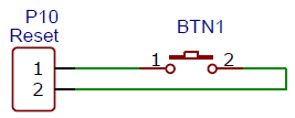
Power
The module can be powered in several ways:
• Using a 5V power supply. I have used small USB chargers successfully.
• Using batteries. In this case I have tested 2 configurations.- Using 2 1.5V cells and a voltage booster or buck converter
- Using 3 1.5V cells directly.
• Using a 5V power supply and a rechargeable LiPo cell for backup.

a) Power Supply
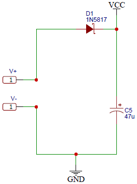
The use of diode D1 is optional and can be replaced by a jumper.b) 2 Cells
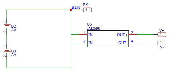
Set a jumper cable in the position of D1 and other between pins 1 and 3 of U2 (3.3V Regulator). The regulator U2 is not required.c) 3 Cells
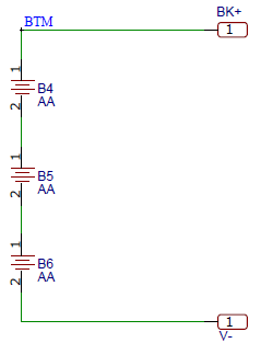
Set a jumper cable in the position BAT and other between pins 1 and 3 of U2 (3.3V Regulator). The regulator U2 is not required.d) Power Supply with Backup
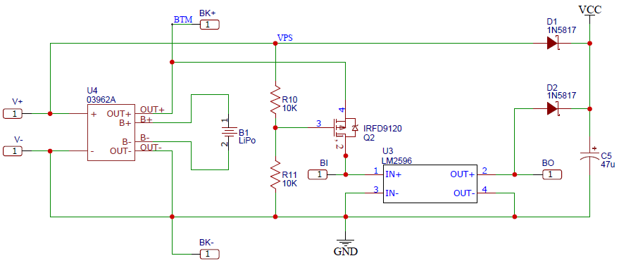
Interruptions
The Arduino Mini Pro has 2 hardware interruptions that can wake up the module from sleep. This module supports 4 elements that require these interruptions:
• Motion sensor (IRQ3)
• Door sensor 1 (IRQ2)
• Door sensor 2 (IRQ3)
• Reset / Test / Calibrate button (IRQ2)
The button is required to operate the alarm and is also used to calibrate the air quality sensors.
The Door Sensor 1 and Button share the same interrupt by default, so you have to select between these two features, also the Motion Sensor and the Door Sensor 2 use the same pin, so you have to configure one or the other.Sleep Cycle
During normal operation, the microcontroller reads the status of all sensors, then goes into a sleep cycle for one minute, to minimize power consumption. The controller can wake up after the time has elapsed or if activity is detected in the sensors that have hardware interruptions.
The sleep cycle can be disabled temporarily if:
• Alarm is On
• The button is pressed
• MQ-7 sensor is enabled
• Wait for child initial presentation to occur
And it is permanently disabled if:
• The button is set in pins 1 or 6
• MQ-7 sensor is permanently enabled
• The module is configured as a repeater for the MySensors networkBill of material
Name [Designator] {Quantity} <Description> Link
- nRF24L01+ [MK1] {1} <Radio Module> https://www.aliexpress.com/item/10000372208801.html?albagn=888888&&src=google&albch=search&acnt=479-062-3723&isdl=y&aff_short_key=UneMJZVf&albcp=12418603669&albag=123937843851&slnk=&trgt=dsa-388903995542&plac=&crea=500813265823&netw=g&device=c&mtctp=b&memo1=&albbt=Google_7_search&aff_platform=google&gclid=Cj0KCQjwsLWDBhCmARIsAPSL3_26vFraRXRKSiLvnpw5r6VG185Dv2SepehHrzutSnjwRq0ZYPzb4ygaAuSgEALw_wcB&gclsrc=aw.ds
- ArduinoProMini [U1] {1} <Microcontroller> https://www.arduino.cc/en/pmwiki.php?n=Main/ArduinoBoardProMini
- L78L33ACZTR [U2] {1} <3.3 V Linear regulator> https://www.digikey.com/en/products/detail/stmicroelectronics/L78L33ACZTR/1038305?s=N4IgTCBcDaIDIHYAccDMqCCBhAWgFQCUQBdAXyA
- 03962A [U4] {1} <LiPo Battery charger > https://www.addicore.com/TP4056-Charger-and-Protection-Module-p/ad310.htm
- LM2596 [U3, U5] {1} <DC-DC Boost Converter Step-Up. NOTE: Make sure to get a Step-Up converter and not a Step-Down.> https://www.itead.cc/power/dc-dc.html
- 0.1u [C1] {1} <Ceramic Capacitor> https://www.digikey.com/en/products/detail/kemet/C326C104K3G5TA7301/6671327
- 10u [C2, C3, C4] {3} <Electrolytic Capacitor> https://www.digikey.com/en/products/detail/panasonic-electronic-components/ECA-1EM100I/2688677
- 47u [C5] {1} <Electrolytic Capacitor> https://www.mouser.com/ProductDetail/Nichicon/UVR1E470MDD1TA?qs=nd5JBRjZIXgOh2LQ2cd6pg%3D%3D
- 1N5817 [D1, D2] {2} <Schottky Rectifier > https://www.mouser.com/ProductDetail/ON-Semiconductor-Fairchild/1N5817?qs=Ro3gc6G1sTm8wr1Du93jFw%3D%3D
- BC547BTA [Q1] {1} <NPN Transistor> https://www.mouser.com/ProductDetail/ON-Semiconductor-Fairchild/BC547BTA?qs=TABiY4F6Vcf01oKZdNLa0w%3D%3D
- IRFD9120 [Q2] {1} <MOSFET > https://www.mouser.com/Search/Refine?Keyword=IRFD9120
- 22k [R3] {1} <Resistor 1/4W> https://www.mouser.com/ProductDetail/TE-Connectivity-Holsworthy/CBT25J22K?qs=VHcS2MTj4gYx622ynmvRcg%3D%3D
- 1M [R4, R12, (R8)] {2} <Resistor 1/4W> https://www.mouser.com/ProductDetail/TE-Connectivity-Holsworthy/CBT25K1M0?qs=vLWxofP3U2yRkXFSovy3WQ%3D%3D
- 330K [R5] {1} <Resistor 1/4W> https://www.mouser.com/ProductDetail/Kamaya/RC1-4334KTB?qs=F5EMLAvA7IBvU3lvZkWOPQ%3D%3D
- 100 Ohm [R6] {1} <Resistor 1/4W> https://www.mouser.com/ProductDetail/TE-Connectivity-Holsworthy/CBT25J100R?qs=VHcS2MTj4gan3wTTNkvgnA%3D%3D
- 1K [R7] {1} <Resistor 1/4W> https://www.mouser.com/ProductDetail/TE-Connectivity-Neohm/CBT25J1K0?qs=VHcS2MTj4gbgcyA0qV722Q%3D%3D
- 10K [(R8), R10, R11, R13, R14] {5} <Resistor 1/4W> https://www.mouser.com/ProductDetail/TE-Connectivity-Holsworthy/CBT25J10K?qs=VHcS2MTj4gYWJg5s4QtMBw%3D%3D
- 47k [R1, R2, R9] {3} <Resistor 1/4W> https://www.mouser.com/ProductDetail/TE-Connectivity-Neohm/CBT25J47K?qs=VHcS2MTj4gbIt9aO8l9ysw%3D%3D
- Buzzer [X1] {1} <Piezo Trasnducer> https://www.digikey.com/en/products/detail/murata-electronics/7BB-20-6L0/4358152
- LiPo [B1] {1} <LiPo cell> https://www.digikey.com/en/products/detail/mikroelektronika/MIKROE-4471/13679389
- AA Battery [B2, B3, B4, B5, B6] {2 - 3} <AA Rechargeable Battery> https://www.mouser.com/ProductDetail/Panasonic-Battery/HHR-70AAAB7?qs=1VjY50kO94REvXlpJrz3gA%3D%3D
- BI [BI, BK+, BK-, BO, V+, V-] {1} <2.54mm Header> https://www.mouser.com/ProductDetail/TE-Connectivity-AMP/5-826938-0?qs=xF5SkmKSM747%2BA1%2FGulWHw%3D%3D
- BK+ [P1, P2, P3, P4, P5, P6, P7, P8, P9, P10, P11] {1} <2.54mm Header>
- Button [] {} <>
- Push Button
- Dupont Cables
Software
[0_1618667254871_MultiSensor03.ino](Uploading 100%)Assembly
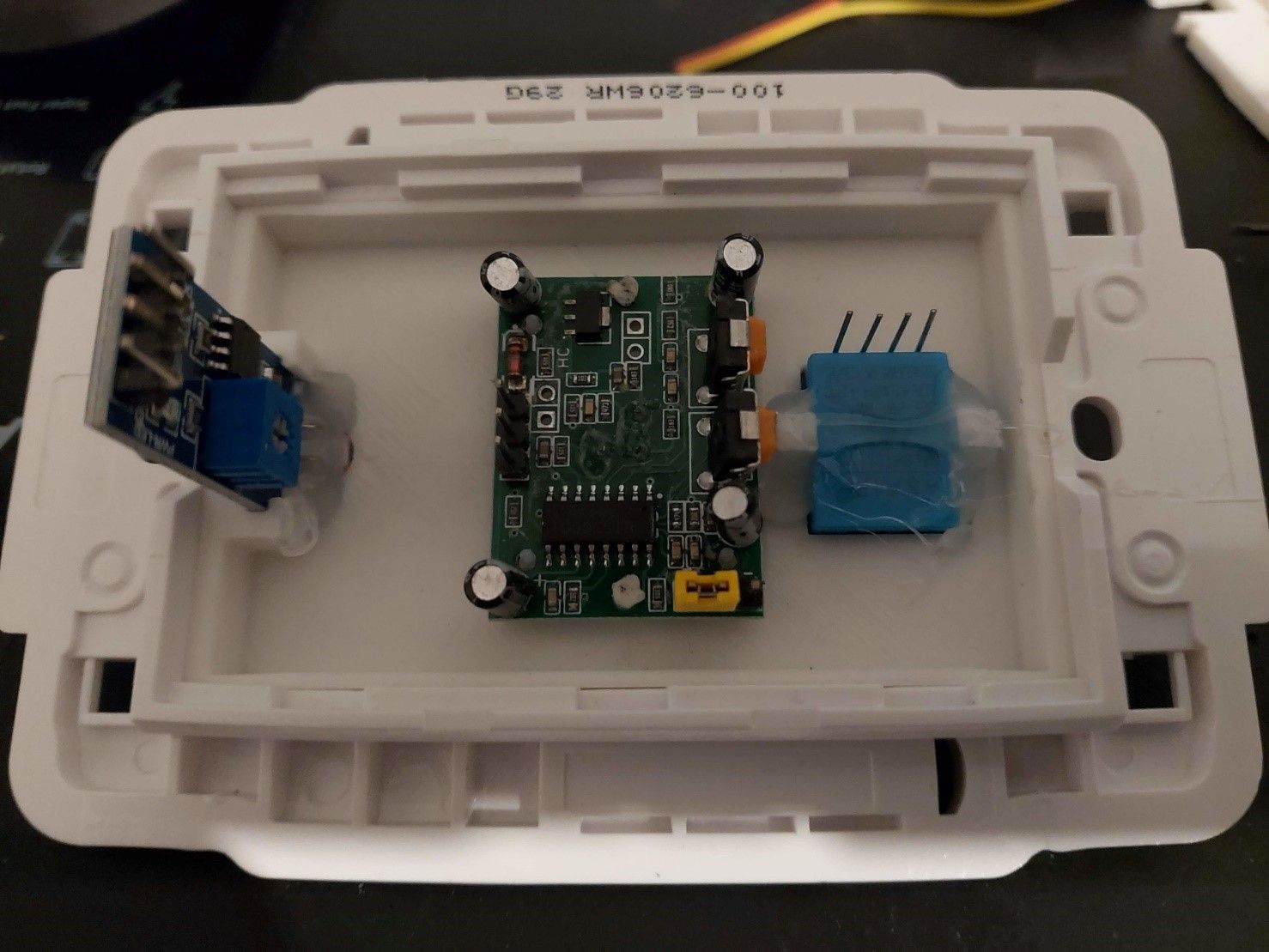
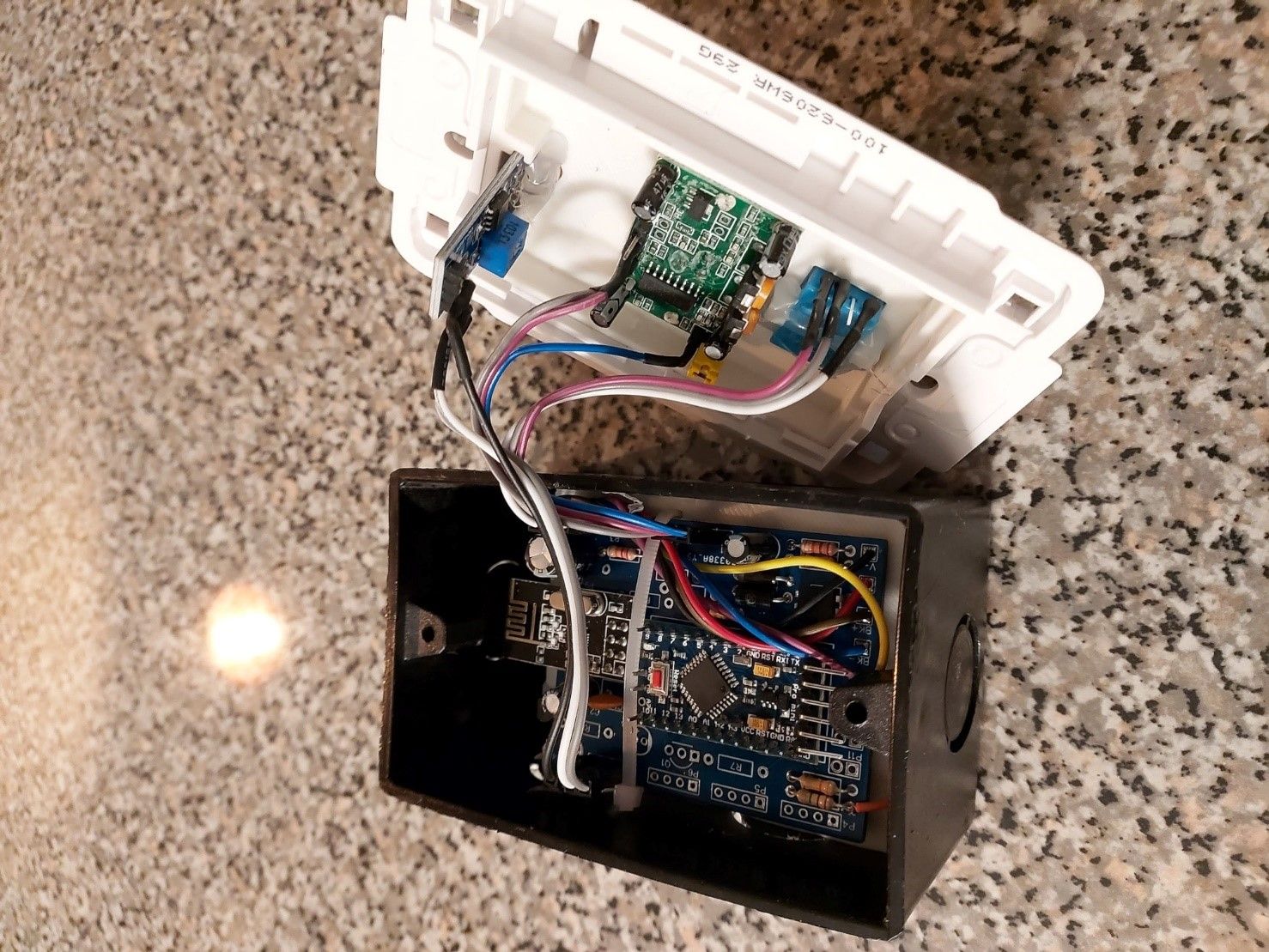
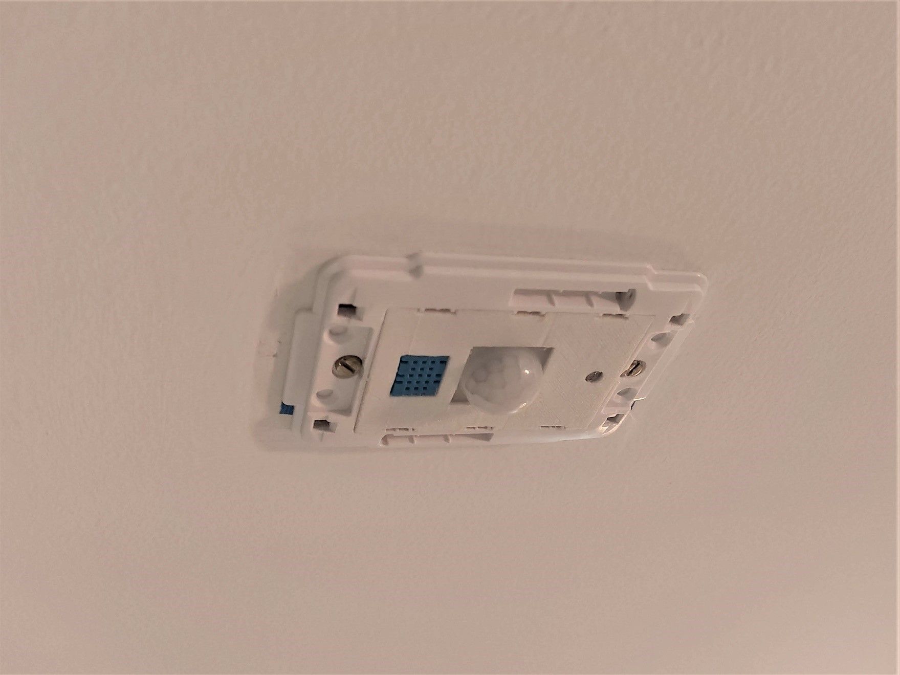
Motion / Light / Temperature moduleBelow are the images of the module assembly with motion, temperature / humidity and light level sensors.
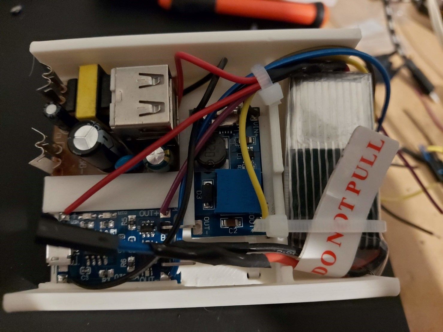
The module is powered by 120V using a 5V USB charger and battery backup.PCB
Power elements. USB Charger, Battery charger, Buck converter and LiPo battery.
Left to right: Light, Motion and temperature sensors.
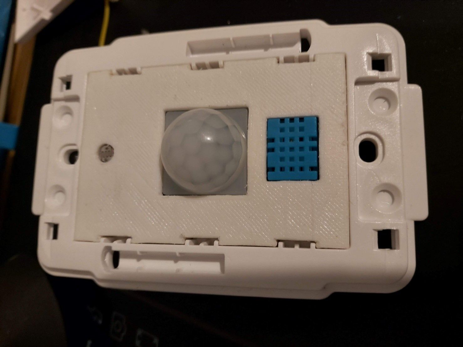
Full assembly.
Module mounted on the ceiling drywall.
-
@jamozu Congratulations!!! Incredible
-
@jamozu Wow! - You have put a lot of thought into not only your project but in documentation as well. Thanks for kindly sharing your project, I am sure many people will find this useful!

-
The Sketch is located here:
https://github.com/jamozu/multisensor
-
Thank you very much for sharing, this is really helpful to me
-
This is really amazing and exactly what im searching for.
where do you get the PCB from?
-
@davedeluxe I ordered the PCB from JLCPCB. The design is available here:
https://oshwlab.com/jamozu/multi_project_copy_copy_copy_copy_copy_copyAnd the sketch is available here:
https://github.com/jamozu/multisensor
Suggested Topics
-
Welcome
Announcements • • hek