nano & E01-ML01SP4 gateway
-
Hi,
I am design my first gateway, serial, (waiting for the parts to be delivered) with an arduino nano and a E01-ML01SP4 module.
Before i order the pcb i wanted to ask the community if my drawings were right.
My questioning are :-
1: about logical level conversion, i choose to go with a simple resistive bridge divider as with spi lines are one way. Do you think its ok or should i go with a more sofisticated solution, like bss138 level shifter, or 74AHCT125N, or TXS0108E ?
-
2: about my wiring on the pcb, does my design is correct regarding interference and SPI data transfert, which i understand is a critical point
-
3: is it ok to power the E01-ML01SP4 module with the 3.3V out of the arduino nano (i added a 47µF Cap to ground just before the module)
here are my schematics and pcb design
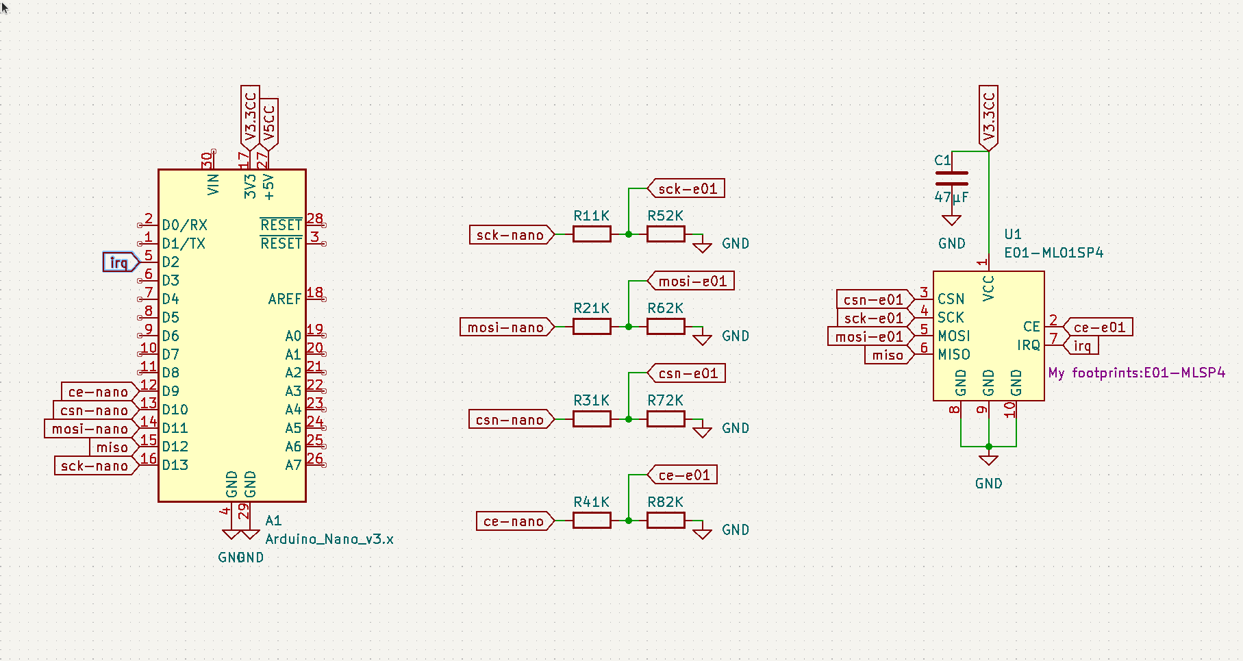
TOP (with nano, E01-ML01SP4, and full ground zone, i am imaging that's good for interferences)

BOTTOM (with the resistors)

thanks for your advises

-
-
hello,
i updated my project as i stupidly inverted the pins on the e01-ml01sp4 footprint ...
i refactored the pcb and also added status led and inclusion button.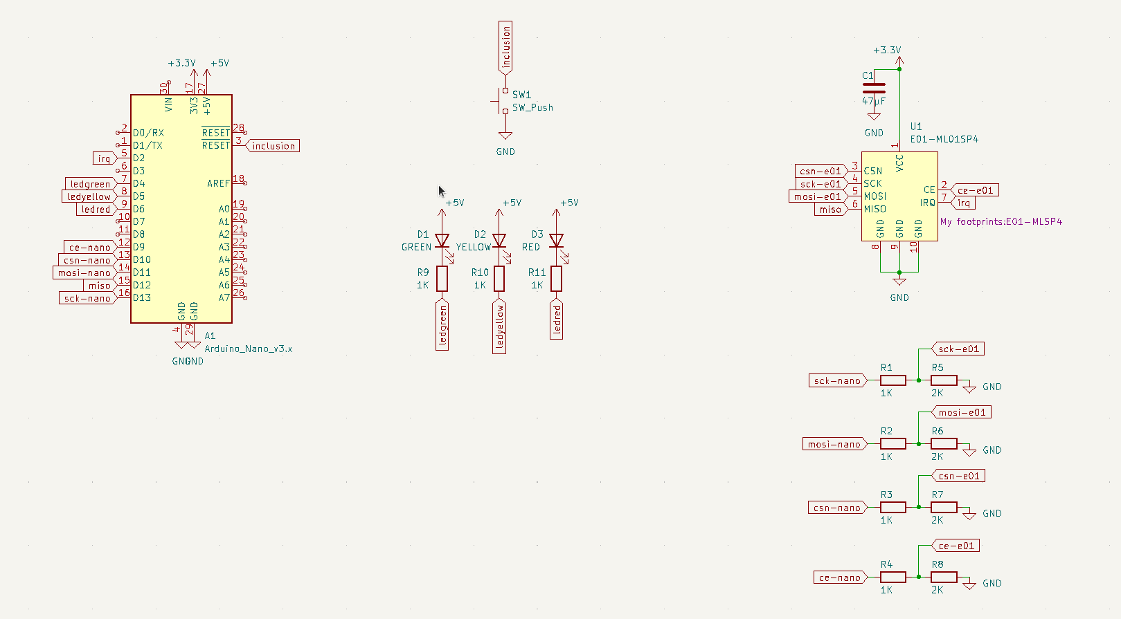


-
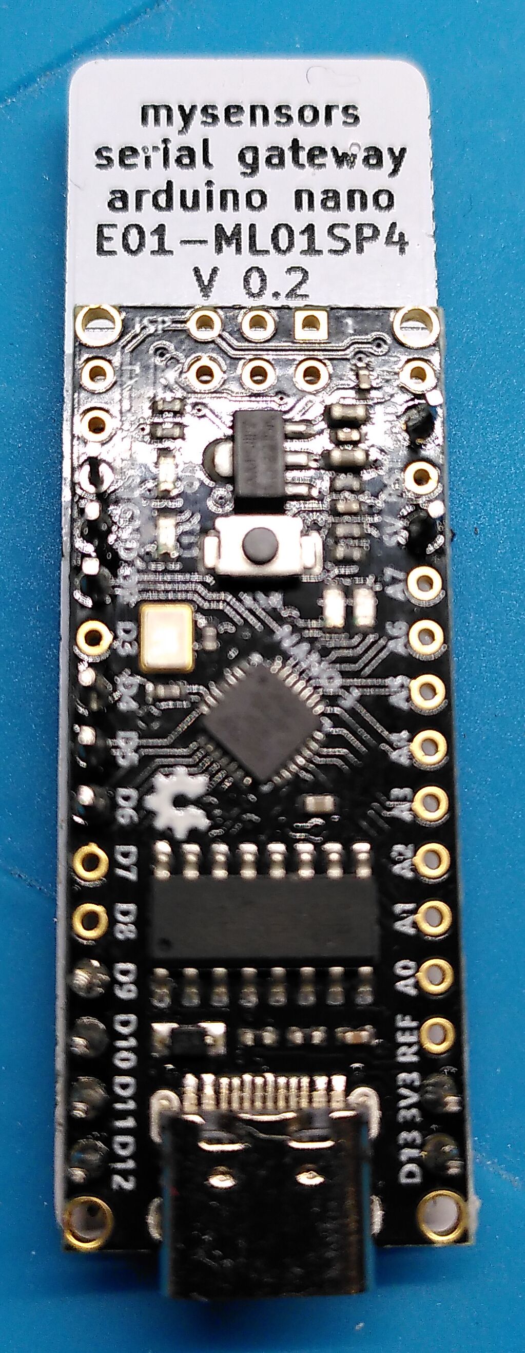
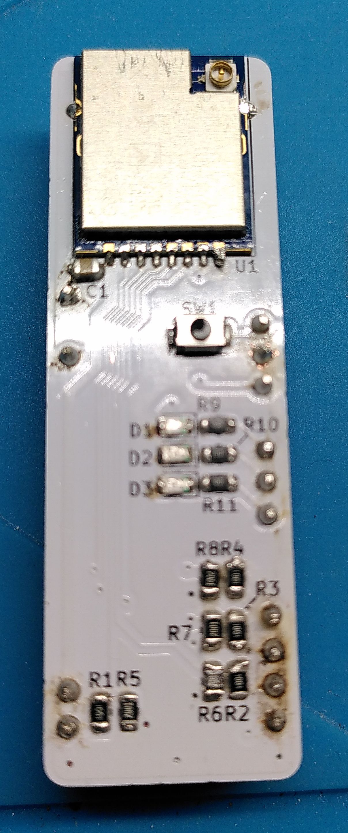
and some pictures
-
i refactored entirely again my gateway as 3.3V pin from nano is not powerful enough (50mA) for the e01-ml01sp4 (120mA)
nano is rebooting when attempting connexion or serial readinghere is the new schematic and pcb
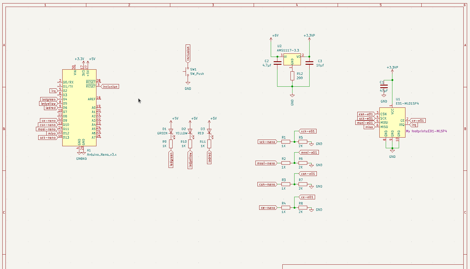
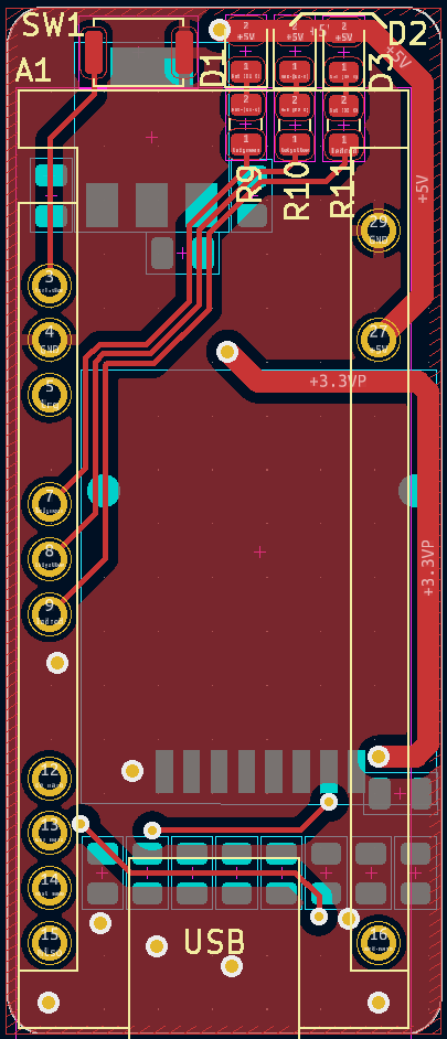
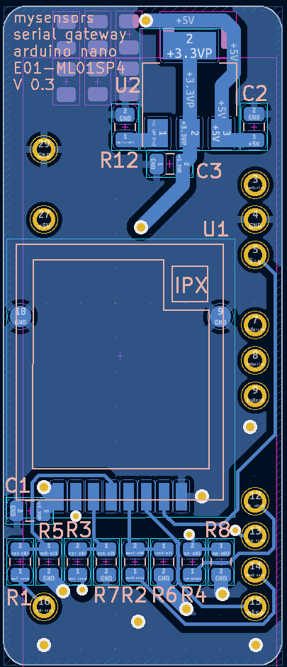
-
You don't need resistors to drop voltage on data pins for NRF24, they are 5V tolerant. Also you don't need SO much capacitance
 4,7uF is enough for stable work, as per my experience. Better add second cap 0.1uF in parallel to the big ones. Also, why is AMS1117 connected to ground via resistor?
IRQ pin does nothing in current (and probably the last) version of MySensors, so you can skip routing it if it will help you in any way.
-
hello @monte
thanks for your feedbacksmonte about 4 hours ago
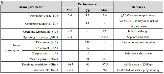
You don't need resistors to drop voltage on data pins for NRF24, they are 5V tolerantfor generic nrf24+ module yes i know
but that's not what the e01-ml01sp4 datasheet is saying, so i prefer to be prudent, it can't do any arm ("ça mange pas de pain" in french)
Also you don't need SO much capacitance
 4,7uF is enough for stable work, as per my experience. Better add second cap 0.1uF in parallel to the big ones.
do you mean 4.7uF for C1 instead of 47uF?
and where would you put the 0.1uF ? on the output of ams1117 or in the input of nrf24 ?Also, why is AMS1117 connected to ground via resistor?
i can't explain it as i don't fully understand it, i followed this tutorial https://maker.pro/arduino/projects/how-to-use-ams1117
IRQ pin does nothing in current (and probably the last) version of MySensors, so you can skip routing it if it will help you in any way.
ok, good to know, my pcb is already ordered but i'll remember that for my coming nodes.
in current (and probably the last) version of MySensors
may i ask why, what do you mean ?
i'm new here, and as a free software enthusiaste developper discovering home automation since 2 years now (expensive closed zwave, closed zigbee then closed ptvo), i was super glad to finally find a project like mysensors, and on my way to explore it, i progressively understand that it's not as active as it was
-
I believe that what @monte is saying that there will probably be little future support for the nRF24 at MySensors. Having tried a different solution using the nano and the RF24 I am very impressed at the MySensors implementation.
I am uncertain if MySensors utilizes the IRQ capability of the nano/RF24. I assume not and I have found no need for it. That said, you do not want to connect the IRQ because doing so draws an extra 10-20mA! Doesn't sound like much, but in battery operations, people go to great effort to get rid of unnecessary circuitry (remove power LED, and 5V regulator, etc.)
@monte is saying to use both capacitors 4.7μF electrolytic and 0.1μF ceramic. I use only a 10μF and am having good success, though if I were doing a circuit board, and going for robustness, I'd used both. Put them as close as you can to the radio. I would also seriously consider a ground plane layer.
I would recommend a socket for the radio. There is some variability in the RF24, mostly depending on manufacturer (particularly if you're getting them from AliExpress!) If your application is extreme, you'll want to sort through to find the one that works the best. (look for the one with the fewest NAKs),
I have tried put the nano in a socket and have had zero real success at having the radio work with it. I put shielding around it and had some pathetic improvement. I suspect that if you did put a socket for the nano on your board, you would need a ground plane.
You might want to bring out RX & TX which is handy in looking at the output when you're running off of a battery. I use this and connect the grounds and then nano RX to adapter TX.
Good luck with your project
OSD
-
@bach e01-ml01sp4 is just a wireless module produced by EBYTE based on NRF24 plus PA/LNA chip to improve the signal. If you take off the metal lid you will see Nordic's chips there. Operating voltage means power supply, VCC pin. Digital IO of NRF24 is 5V tolerate. But you do you.
@bach said in nano & E01-ML01SP4 gateway:
i can't explain it as i don't fully understand it, i followed this tutorial https://maker.pro/arduino/projects/how-to-use-ams1117
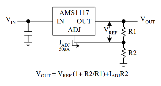
Well, someone have misunderstood something, I guess. Any explanation for a resistor between GND pin and ground is if it is adjustable version of this regulator. And even then it would be used with resistor divider, not just one resistor.
@bach said in nano & E01-ML01SP4 gateway:
and where would you put the 0.1uF ? on the output of ams1117 or in the input of nrf24 ?
Next to the cap you are using for NRF24. All caps work together, but for ensuring the best performance you need to place capacitor as close to actual VCC pin of the chip as possible. In your case it's not possible, because you are using prefabricated module, but you get the idea.
@OldSurferDude said in nano & E01-ML01SP4 gateway:
I believe that what @monte is saying that there will probably be little future support for the nRF24 at MySensors.
No. I am saying that current development of MySensors is basically stalled. And I am not sure if anyone is seriously interested in keeping this project updated.
@OldSurferDude said in nano & E01-ML01SP4 gateway:
@monte is saying to use both capacitors 4.7μF electrolytic and 0.1μF ceramic.
No. The practice of using smaller capacitor in parallel with the bigger one is not limited to only electrolytic ones. Please read this answer: https://electronics.stackexchange.com/questions/298798/capacitor-placement
In this particular case it won't make much difference if any. But it's a good rule to remember if you are planning on making more complex circuits in the future.I may be wrong about IRQ pin after all. It seems to be used with MY_RX_MESSAGE_BUFFER_FEATURE feature. But I see that some people report problems using it and it only works with AVR.
-
Hello guys,
thank you for your intels ! i recieved the pcb and built it, it works
i changed C1 for a 0.1µF, and removed R12
i kept the resistor bridge for isp comm.
i tried to activate buffer with irq but it's going rogue, gave up with that
i doubt that the inclusion button has any utility, it seems to be just an other reset buttonIt gives me a little serial gateway wich size is about the same as a "sonoff zigbee dongle plus"
i'll have to make an enclosure for it now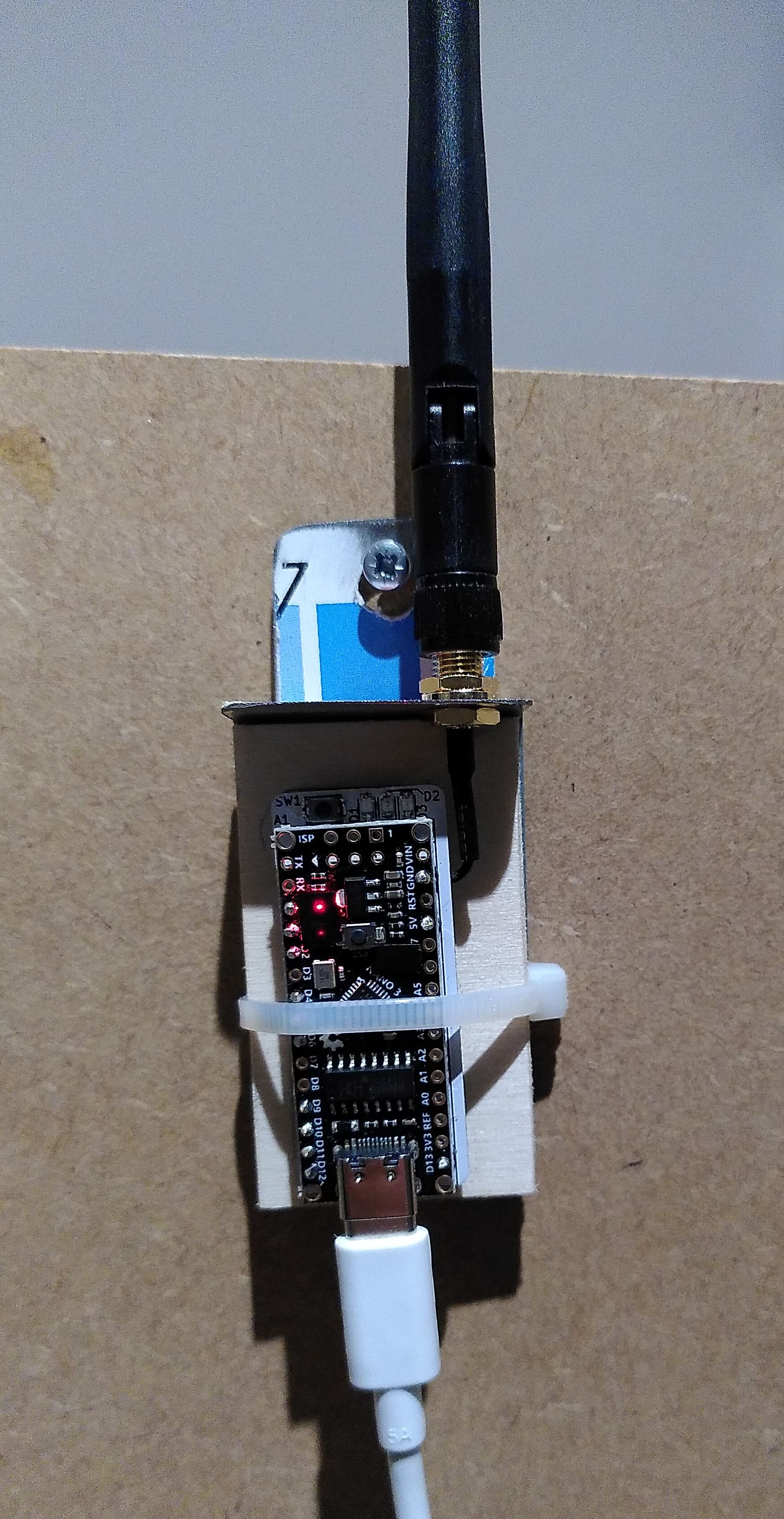
-
@bach It does look really great! As far of resistor divers I'm not much fan of that. There are several other options, like a logic level converter circuit with FETs. If I have all 3.3V devices connected to an mcu I prefer to use a 3.3v mcu. Like an esp2866, but I'm still waiting until the irq support on the esp2866 gets available.
For me the nrf24's are still working great and I have a stacked up a lot lol. I'm however experimenting with the rfm's. As I need a bit more range to reach the end of my backyard.