Safe In-Wall AC to DC Transformers??
-
Would this varistor work with 240v?
http://www.ebay.com/itm/10-x-Zinc-Oxide-Varistor-250VAC-60J-2500A-10mm-/260848704608?hash=item3cbbcb5c60 -
@MartinP Based on my limited knowledge, yes, that should work. Maybe someone else can chime in to confirm?
@petewill said:
@MartinP Based on my limited knowledge, yes, that should work. Maybe someone else can chime in to confirm?
I would personally go with a higher voltage rating. Something like 15-20% higher than your normal voltage otherwise you may get regular nuisance trips. So for a 240 VAC system, I would use something close to 290V.
Cheers
Al -
 :stuck_out_tongue:
 -
Hi all,
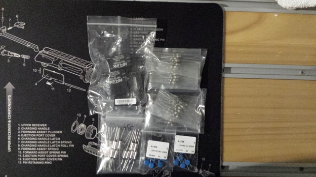
I was wondering, I want to be able to adress my blinds using mysensors. Using the relay, radio etc works fine, yet I am still wondering on this power supply. So using the above component I basically prevent fire by using the thermal fuse and an overload by using a regular fuse, the varistor and the HLK.
Now, I am using a Nano (I have still 15 of those) which appear to be using 230mA, the radio itself and a relay. The relay (from the spec sheet) uses 180mA. This should be ok to be used with the HLK shown above. Now, my main concern is, how do you make a all sit together nicely? Is there a PCB type of board you are using? Any pointers welcome :)
Kind regards
Steve
-
Hi Steve
this may be useful http://forum.mysensors.org/topic/1540/110v-230v-ac-to-mysensors-pcb-board
Regrads
Filip -
-
I'm planning on using the HLK-PM01 with the extra precautions discussed here; gluing a thermal fuse on top of the HLK-PM01 and adding a fuse and varistor.
My only problem right now is that I'm unable to find a good source for 0.3A slow blow fuses with axial leads on eBay. The only variants I can find are without leads and it feels a bit unnecessary to add a fuse holder to the circuit since the fuse is meant to be non-replaceable. The ones that petewill posted a link to are out-of-stock. Does anyone have any good suggestion where to find good fuses to use?
-
-
If I want to use a relay for in-wall use. Could I use the same Slow Blow fuse, thermal fuse and varistor to get it to be more safe?
-
This has been an excellent thread! I am left with one practical question though. How does one safely mount the thermal fuse on the HLK-PM01? Even if the thermal fuse thru hole on the PCB was exactly next to the middle of the HLK-PM01, the lead will still need to run 2+cm to the top of the HLP-PM01, then another 2+cm back down to the PCB. Only the thermal glue holds it in place. It seems it could easily come loose with minimal pressure - and remember it is 110 or 220V! Of course the leads would be protected by electrical tape or shrink tube, but it is still not firmly secured. Plus it is more likely that the leads on both sides would be closer to 3cm, plus the 1 cm for the fuse for a total of ~7cm of high voltage 'leads' not securely tied down to the PCB. I am only a hobbyist, so I am curious to hear others thoughts on this. Also, note that this board (http://forum.mysensors.org/topic/1540/110v-230v-ac-to-mysensors-pcb-board) has great protection, even fuse & varistor on the low voltage side. How would one mount a thermal fuse on the HLK-PM01 without having a 'loose' lead running to the top of the HLK? Or am I over concerned.
-
I would suggest that the PCB have a cutout UNDER the HLK-PM01, so that you could stick the termal fuse under the powermodule against the bottom.
If you look at the images of an opened powermodule, then you will see that the internal PCB is on top. I would expect the heat from any problem to be noticable on the bottom as well.
Could be a safer option (less long wires) ? -
This has been a great thread with a lot of good information. I'm still a little worried about putting something like this in my wall though. What are peoples thoughts on benefits of this approach versus using something like a Samsung cube charger which is about a 28 mm cube (without the prongs), handles 120/240 V, and is probably very safe?
-
My guess is that the HLK-PM01 is of the same quality, but it only gives 700mA @ 5V. On my repeater it never feels warm at all (and this is in a completely closed box).
You could add a temp sensor to monitor and set an alarm in your home control system, maybe a solution to feel more secure. -
What do you think about this ? 1.79$ 5V @ 700mA dim: 3cm x 2cm x 1.8cm :
http://www.ebay.fr/itm/321846469504?_trksid=p2060353.m1438.l2649&ssPageName=STRK%3AMEBIDX%3AIT
