50mm x 50mm board with different powering options
-
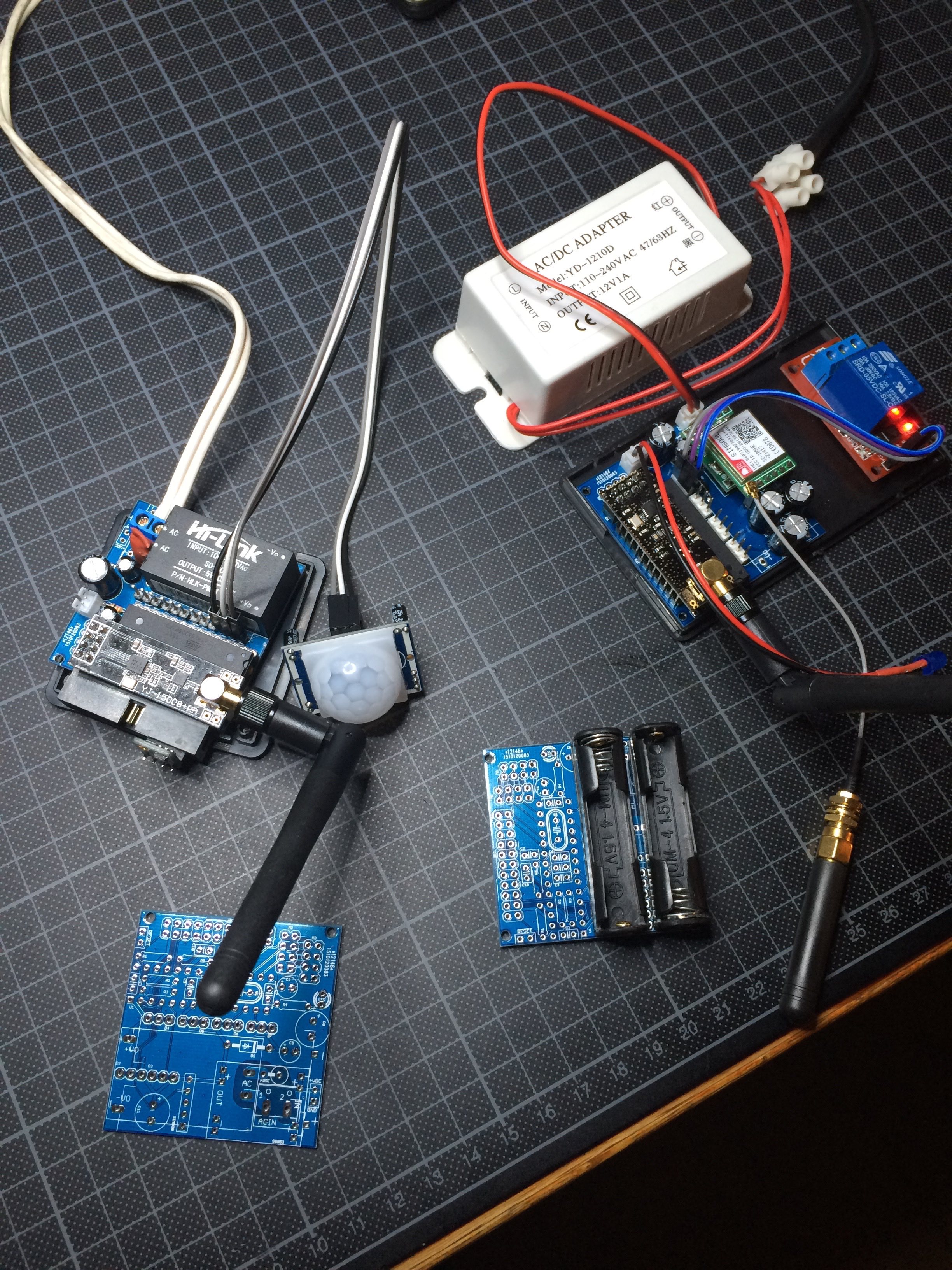
Still testing this PCB, but so far everything is working. I now have a board which I can use in different power configurations.
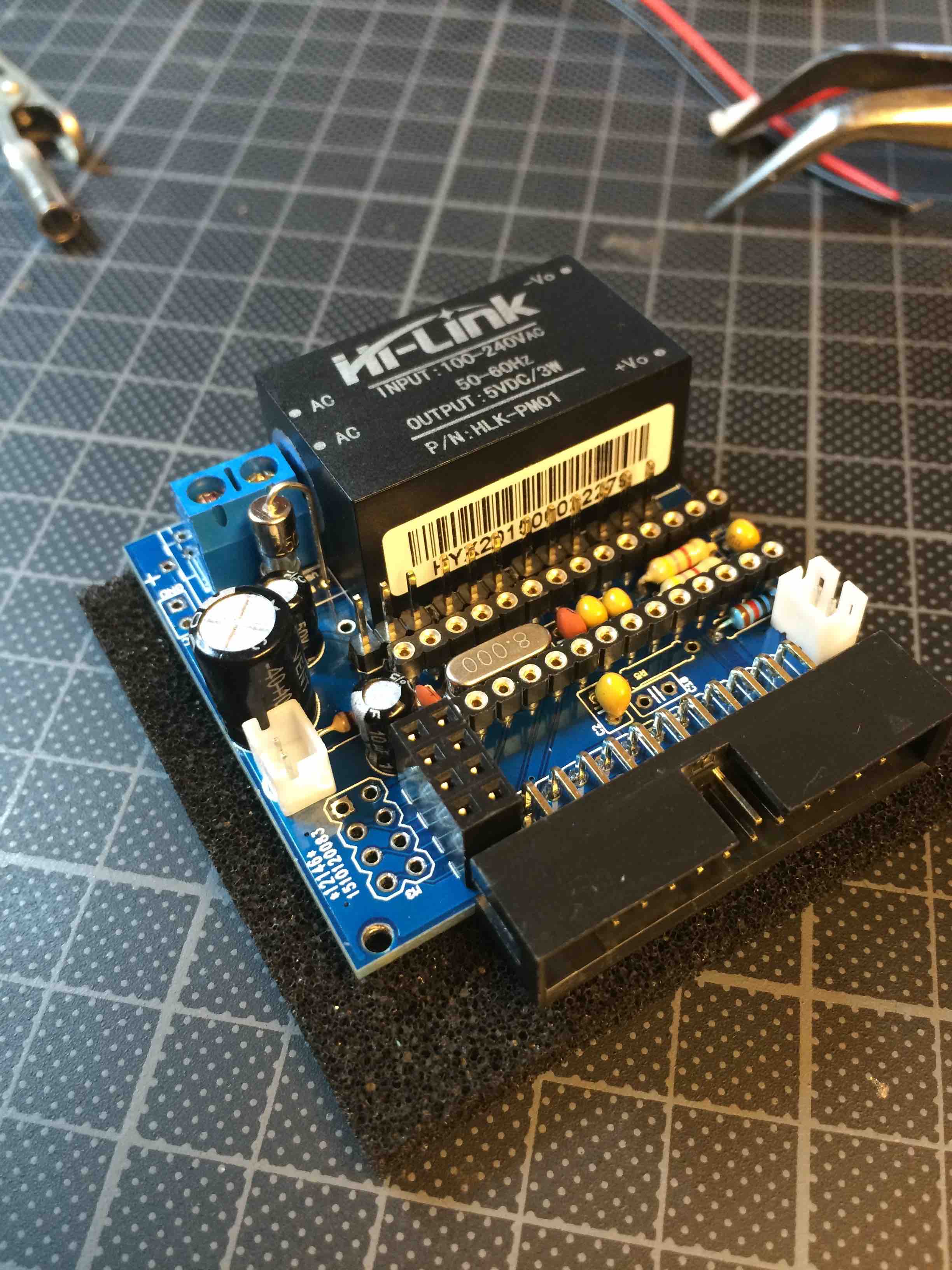
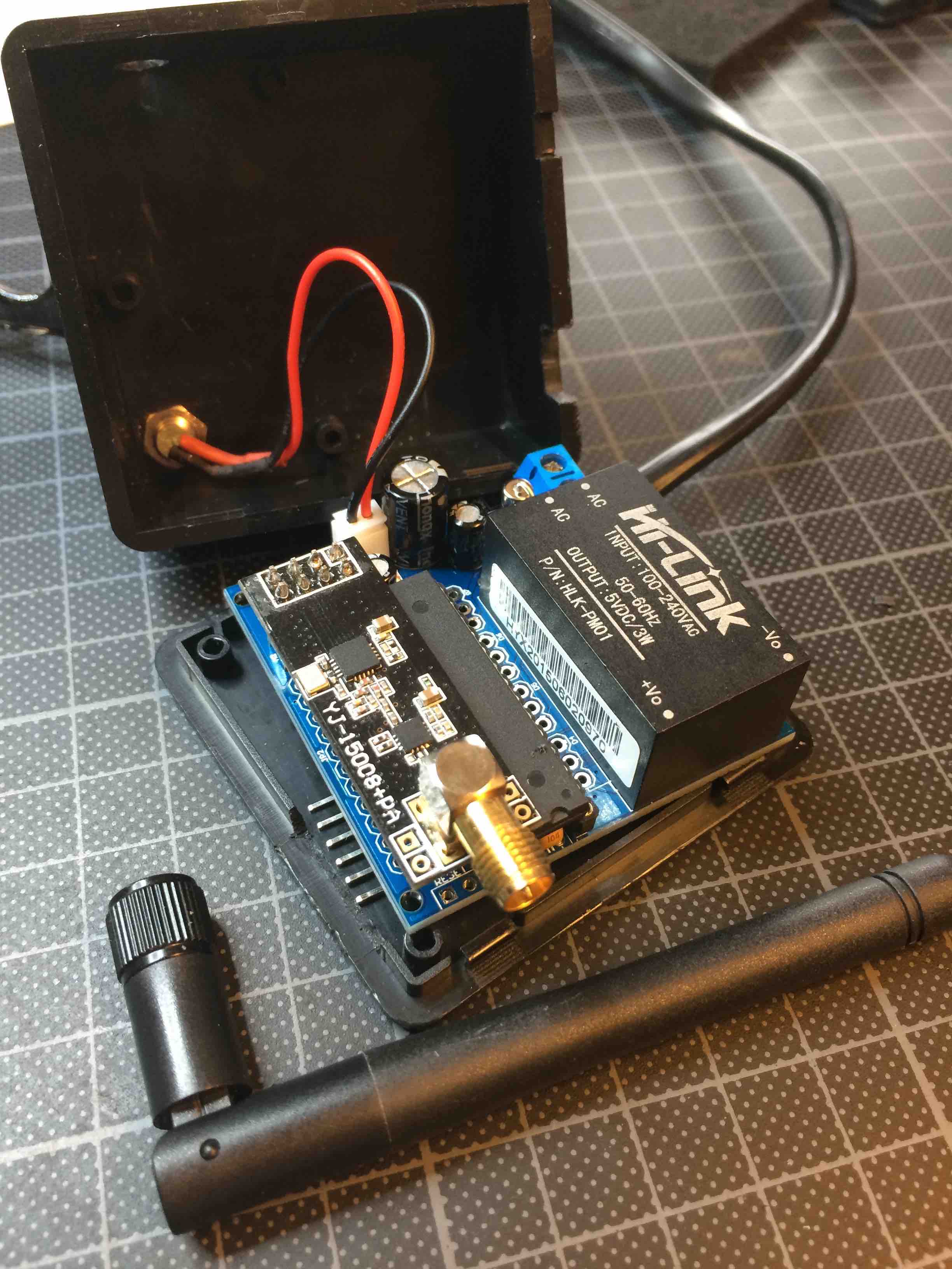
Upper left is powered by 220V AC directly, an HLK-PM01 takes care of bringing that down to 5V. The radio gets power from an AMS1117-3V3 mounted on the bottom side of the board.
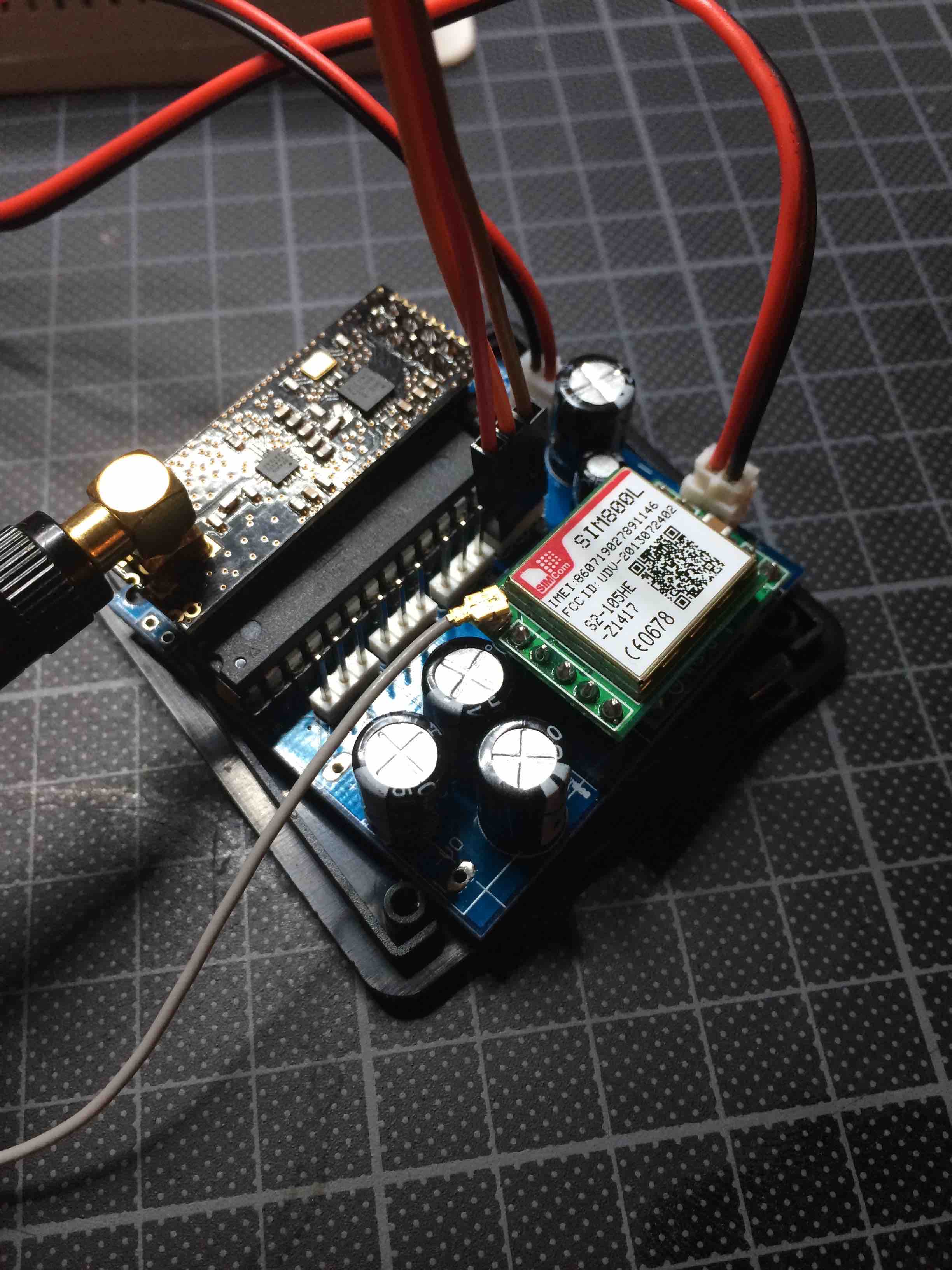
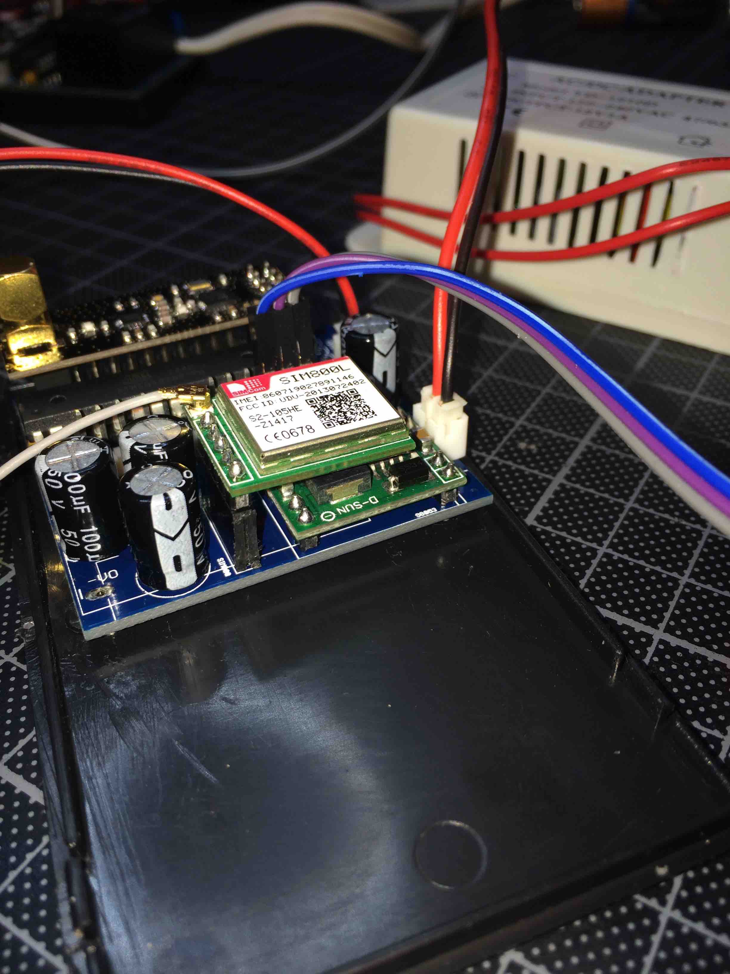
Top right is a board powered by 12VDC, with conversion (a 3A DC-DC step-down module) to 4V for the SIM800L (GSM module) and this is dropped to 3.5V by passing a rectifier diode, for the radio. Both are running repeater code in combination with some sensor code.
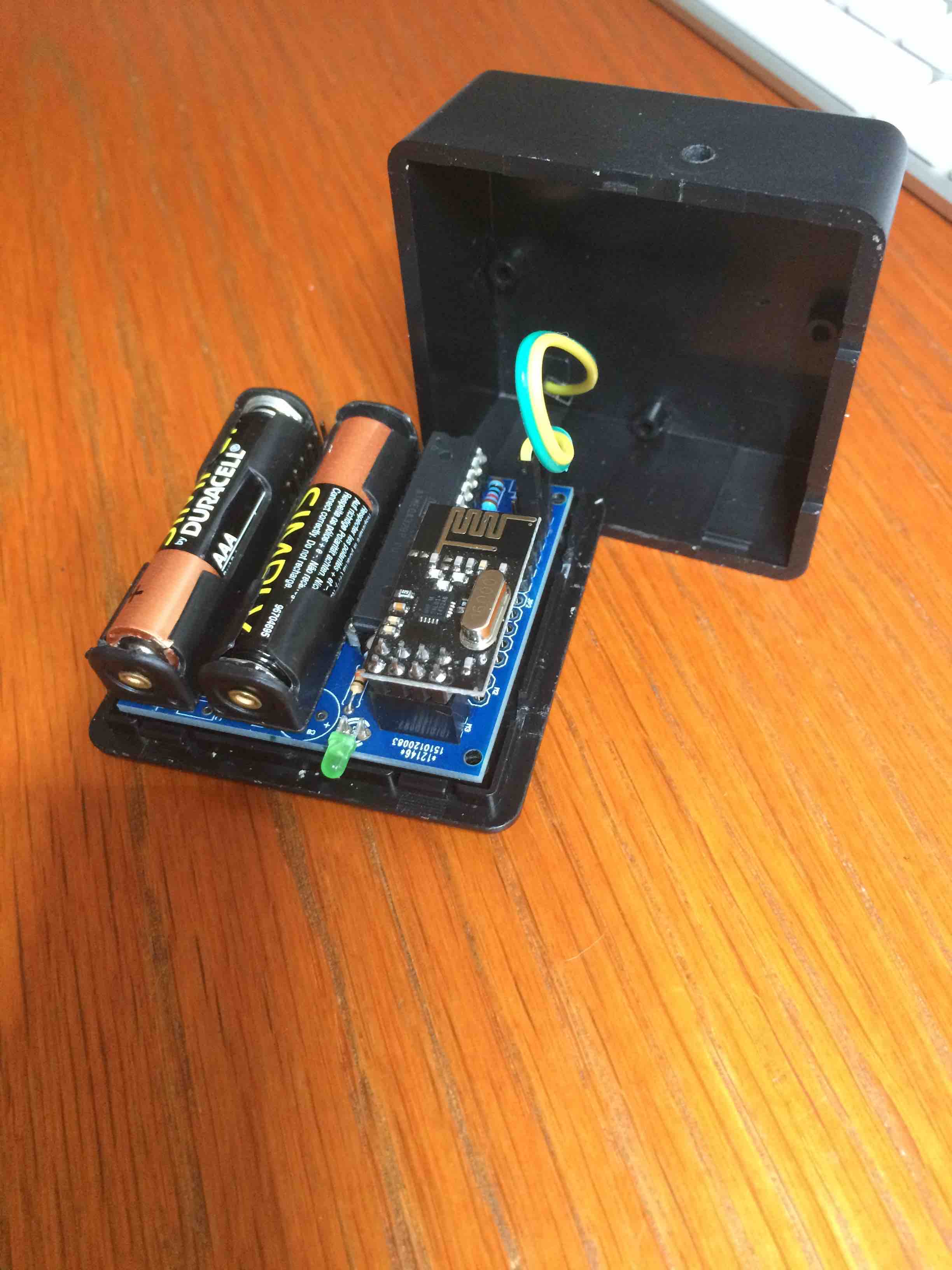
In the middle the version based with two AAA batteries, which I still need to assemble. It will be interesting to see if this also has a sleep current consumption of 1.45 uA like it's little brother (my GSRedboard)I will do a writeup later, as I have a few improvements in mind, and I prefer to test everything first.
Just to show that using the Mysensors library allows me freedom to make stuff I (think) I need :-).
-
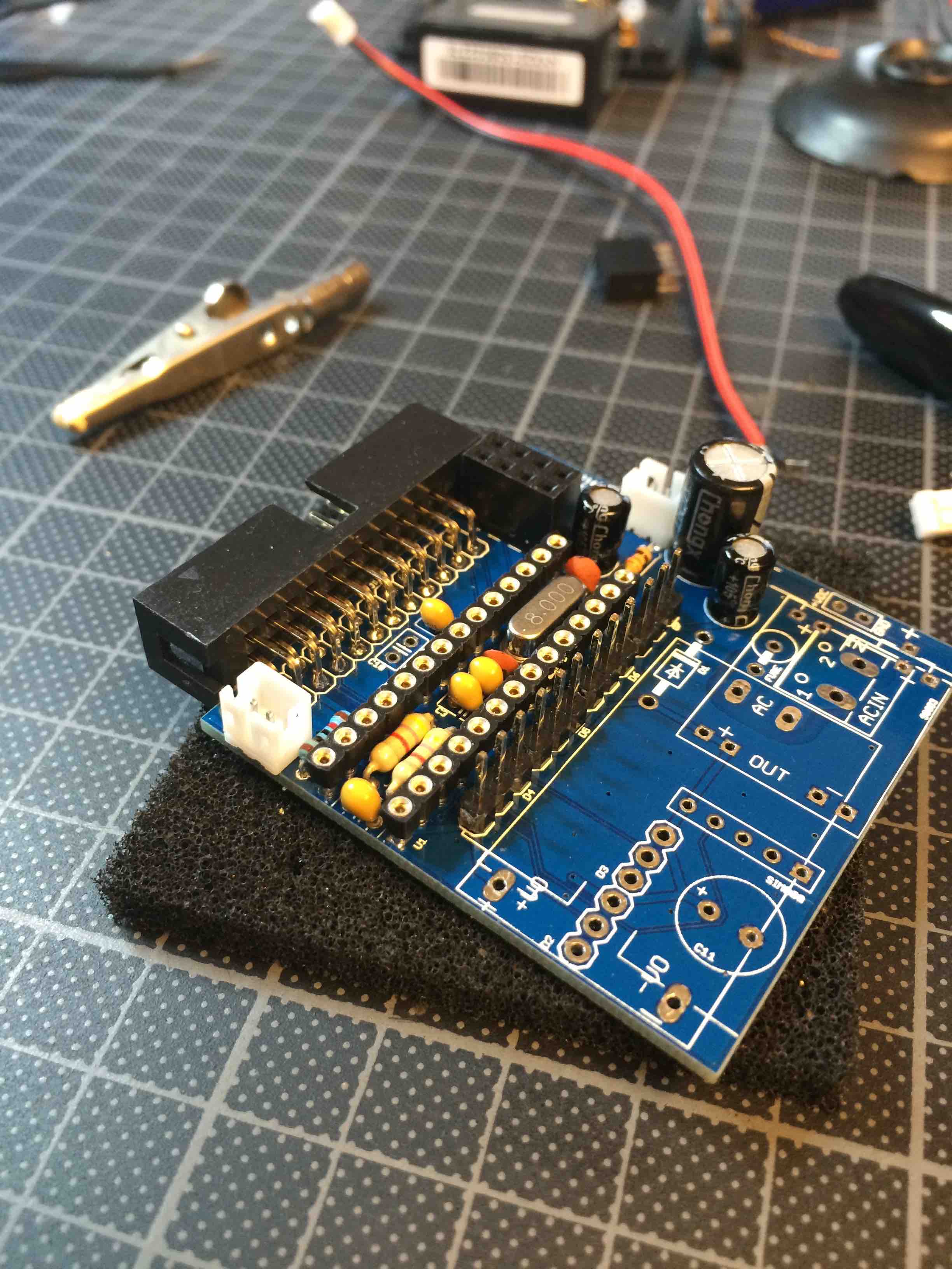
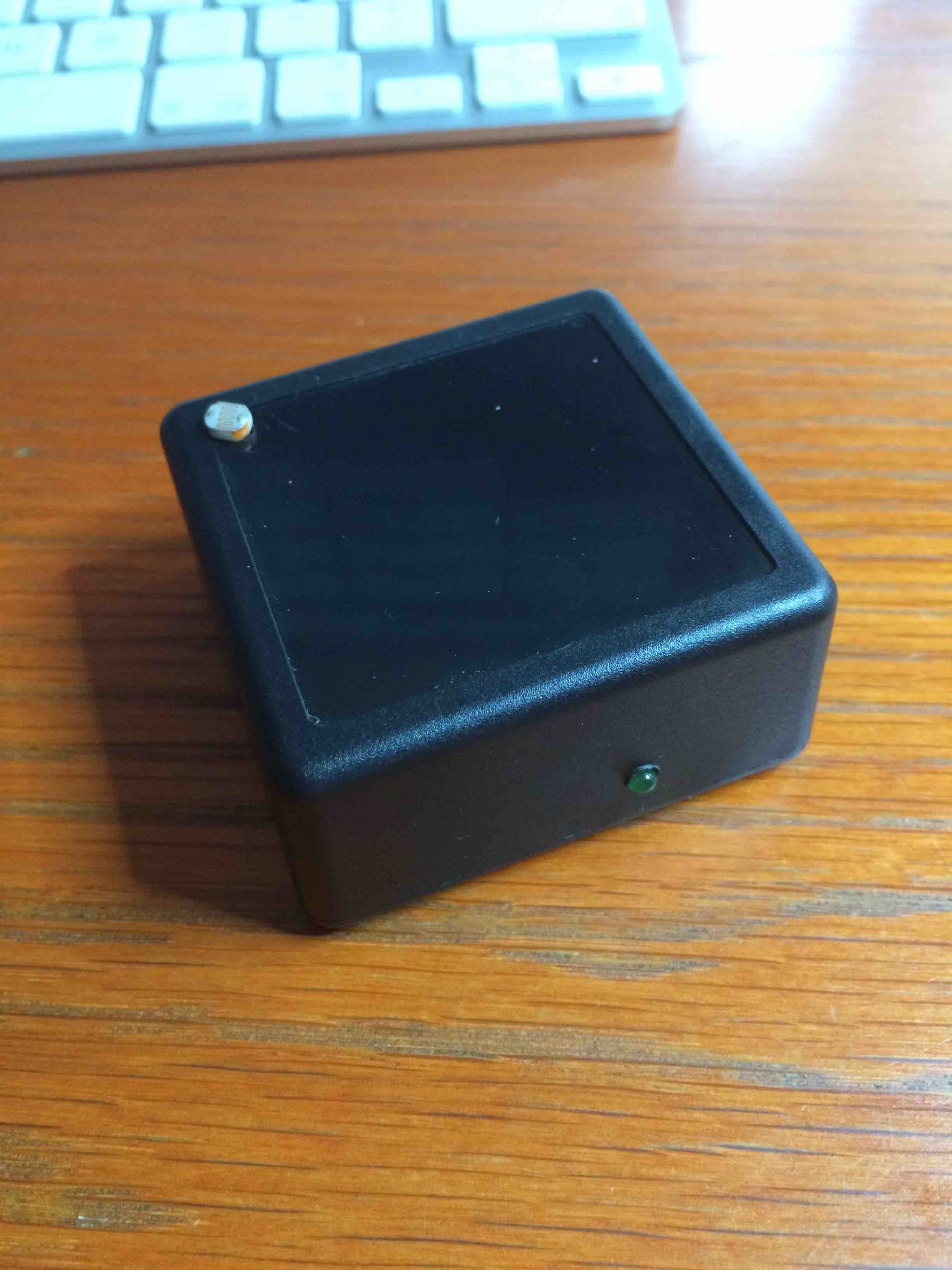
The battery version of the board also works. Below it is in a light sensor version. A repeater was made as well.
The battery version:
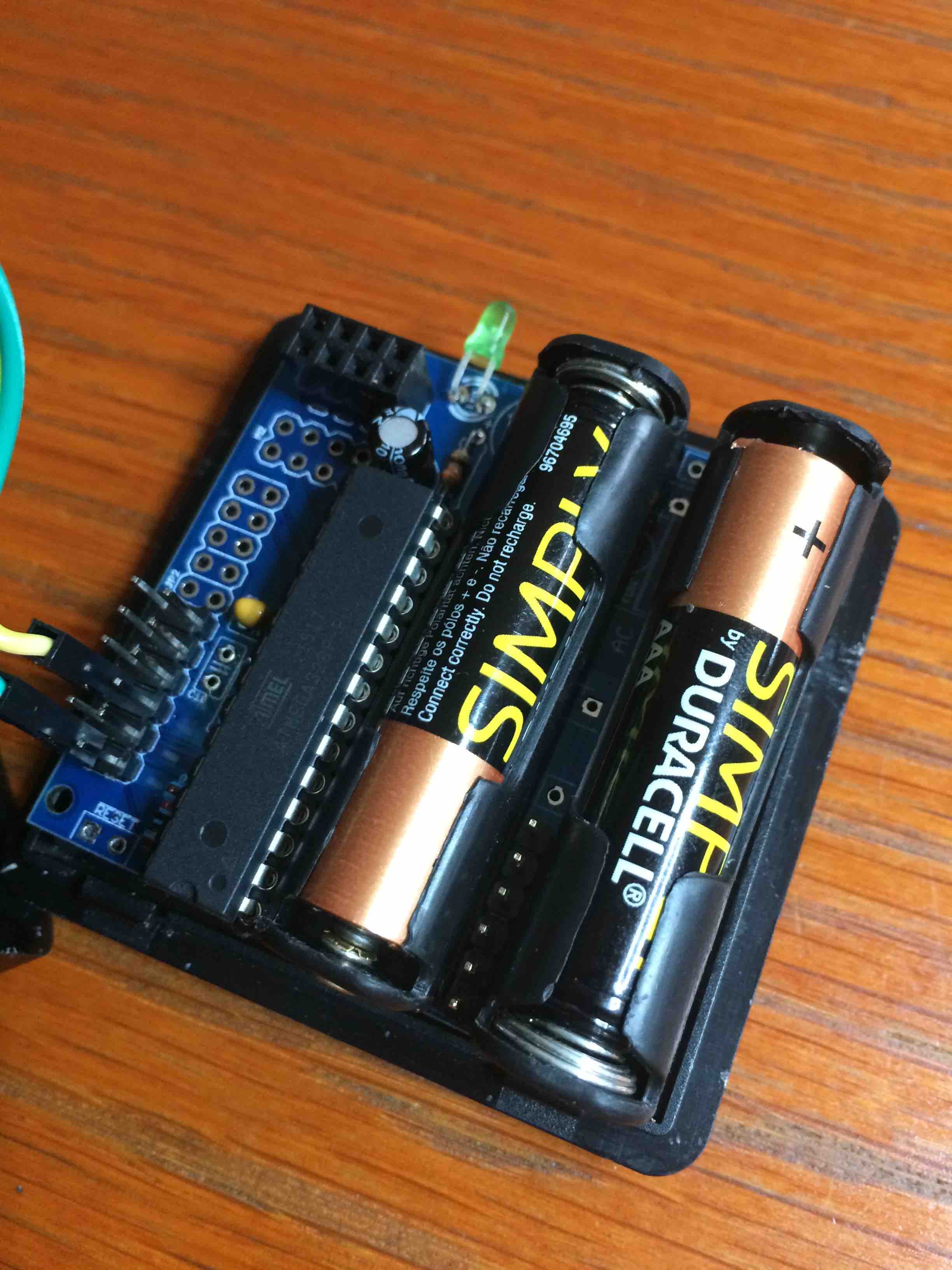
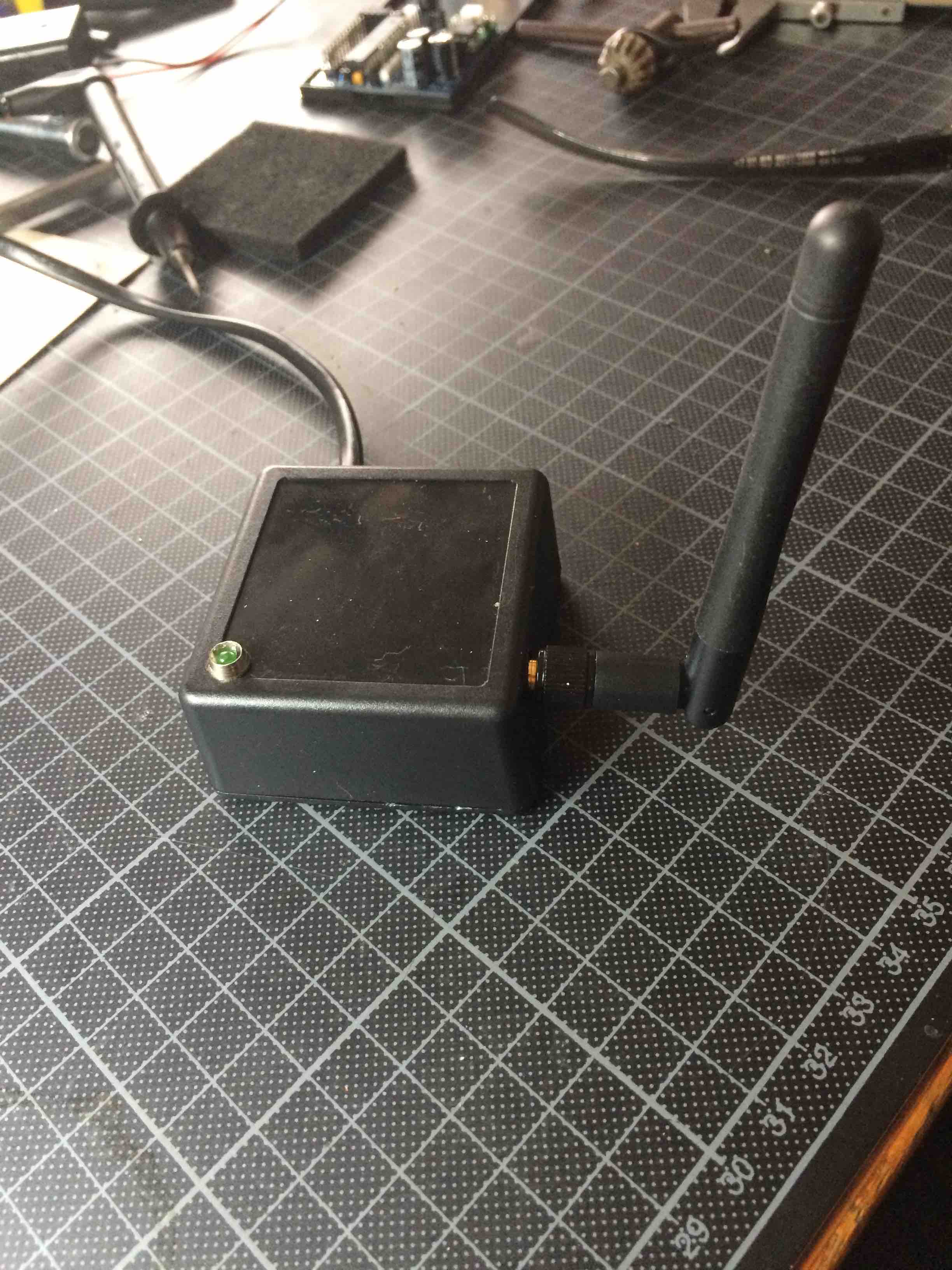
The repeater:

-
I see you have the SIM800L module. Doesn't it just work in china GSM networks?
-
@hek No, it also works on our networks in Belgium. It is a quad band GSM, so it basically works everywhere. I use it to send messages over the BASE network. I also used it on the PROXIMUS network, so I can attest that it works in Belgium. For less the 7 EUR on Ali-express you can get a model with GSM antenna && attenna in PCB form (both in the package). This board only has a reset pin, RX, TX, VCC and GND. Another breakout board also has a power-enable pin (after some hacking), but that one is a bit bigger. The board I use now is really the smallest I could get.
Great fun to enable a pump via SMS and see it on Domoticz.
I applied the FONA library from Adafruit, and it works without a problem. The only issue I had was the size of the message buffer. Making that 160 chars was a bit too much for the 2K RAM limit. But since sensor message payloads are only 25 bytes, I now use a 30 byte buffer, which is plenty to send commands.
-
Was about to create an example for a GSM shield I've had for a while. But when I started playing with it I couldn't get it to connect to any network here in Sweden. Think it was somewhat was broken (suspect antenna/connector). Even upgraded its firmware but no avail.
Well.. Have another shield on the slow boat here.
But I got the impression some of the SIMx00x modules just worked in china. So I ordered a SIM900-variant.
-
Adafruit sells the FONA board to international customers, and it has a SIM800L or SIM800H (last one has GPS functionality as well). So I was pretty sure it would work. To bad your shield is broken.
If a SIMxxx variant uses the Chinese version of CDMA, then that is a local module. But the GSM standard is global. Only base-frequencies can be different. Not a problem for a quad band chip though.
I did find that I needed to provide ample power to the chip, it needs 2A in very short bursts on transmit during initialisation, so sufficient capacitors are needed.
What I used:
http://www.aliexpress.com/item/Quad-Band-Quad-Band-SIM800L-GPRS-Module-Bomb-Slot-Automatic-MicroSIM-Card/32268487416.html
-
Would be great if we have a SIM "mysensors" module, sending and receiving SMS commands and alarm triggers. it could fill the gap from my visonic Power master 10 (i didn't bought the 200€module for gsm)
About the GertSanders boards...just amazing compact AC version...even if you use the mini atmel chip will not save space because you hide all arduino components under the chip ...good job
-
I like @Gertsanders boards too
")
I like all versions of boards which everyone are doing. emulation, crazy thing, so cool to have so much choice")
should not be difficult to make a gsm node..but like Gertsanders said it needs a good power supply. I am making a board with gsm which I will present soon.. but it is not a dedicated gsm node. much more features
will be a surprise lol!
And like GertSanders said it needs a good stepdown. In my case I am using an ap6503sp (3amp)..maybe I will make a basic node if someone needs it. but job seems already done. your boards already handle it Gertsanders, isn't it?
-
Great board, have you got any plans for adding possibility to use RFM69 radios?
-
hi @scalz my board already allows the use of the small SIM800L, in combination with a DC step down module on the board. In the first image you can see it. The DC step down module sits below the SIM800L module. I bring the 12VDC down to 4V, and the NRF24 gets 3.6V because I pass through a rectifier diode ("cheap and simple" step-down).
I use SMS to switch the relay, and at the same time I can see the status in Domoticz. The sketch I made also allows switching the relay from Domoticz too. I now need to extend that sketch so it triggers the relay when two switches are opened (the white 3-pin headers are there for switches). The switches will open when water rises to a certain level, then this triggers the relay which will start a sump pump. At that moment I should get a SMS, and when waterlevel is again below first switch, the relay should be switched off, another SMS sent and my basement equipment safe
That is the theory anyway.My second SMS board uses V_TEXT to receive short text from other nodes and will send that to my GSM. But I'm still waiting on the second SIM800L board to arrive from China.
@Cliff-Karlsson: At the moment I do not have any RFM69 radio's, but my board has a jumper to connect the INTERRUPT pin of the 2x4 header of the NRF24 to pin 2 of the ATMEGA328. In theory you could use an adapter board to connect the RFM69 to a NRF24 header, and with the jumper have all connections needed by the RFM69. Such an adapter board exists on OSHPark.
After some more testing I will put my board on the forum thread where we assemble all the board info:
http://forum.mysensors.org/topic/595/pcb-boards-for-mysensors
-
@GertSanders said:
uses V_TEXT to receive short text from other nodes
Exactly what I planned to do
Crazy minds think alike
-
@Cliff-Karlsson Here is the adapter board:
https://oshpark.com/shared_projects/TKNcHTRl
http://hallard.me/rfm12b-breakout/
-
Thanks for the link. But I can barely solder regular components, it looks like I need to place some smd stuff on that board, I have seen crackheads on cops that have more stable hands than me.
-
To make it a bit easier for some, here are the EAGLE files of this AC capable board.
AC based repeater V3.sch
AC based repeater V3.brd
AC based repeater V3 partlist.txt
AC based repeater V3.pdf
-
Hi,
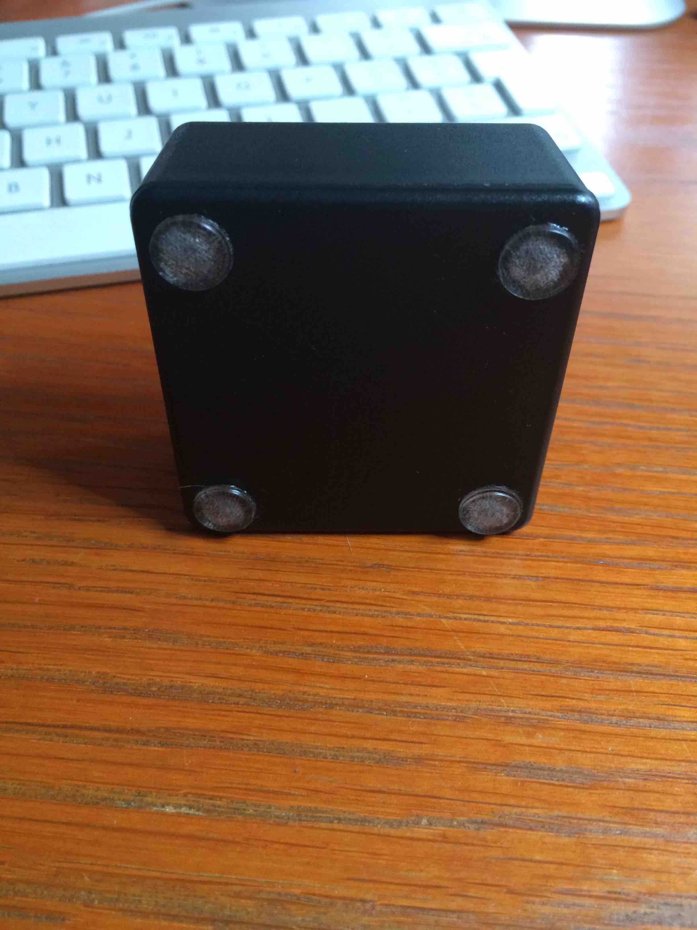
what enclosure did You use for it?
MiKa
-
@gertsanders you have good PCB design skills, great work
 but keep safety in mind, those cheap chines plastic box aren't for 220v and definitely not to houses any power supply.