💬 Easy/Newbie PCB for MySensors
-
@Tommas - this is the voltage regulator that the board is designed for so the markings/pinout will be right for you. If you put 5v on the PCB input and use 3.3v pro mini though, the only choise you have is to put 5v on RAW and let the onboard voltage regulator on the PCB regulate it down to 3.3v. The voltage regulator on the PCB only regulate the voltage to the radio and are meant for a 5v input on a 5v pro mini. Using raw means there is no need for the LE33.
-
@keldandorin - are you using a booster as mentioned above?
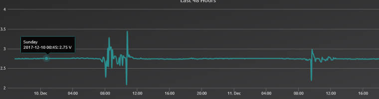
The problem is in that case noice introduces in the radio from the booster (a known issue). I will in the future try to buy me a oscilloscope and diagnose more... but for now, if you add a "bad/cheap" booster it will be this problem. 2.8v sounds really bad though, and most likley a really bad clone.You have two options.
- Try another booster, and/or try to filter with capacitors.
- Load a new bootloader that can handle lower voltages accoring to link above.
Let me know if I can assist you in any way.
@sundberg84 Is there any way to say if booster is a bad one or not before ordering them?
The one I ordered was the one on shoping list from aliexpress. Will try I capacitator and see if I can get a new booster from kjell&Comany tomorrow just to try. Build a setup on bread bord where I powered radio with 2 AA and got the same result. Got a fju places where I like to put some sensors with no power so realy need to get this working :). Could the radiomodules be bad to? -
@sundberg84 Is there any way to say if booster is a bad one or not before ordering them?
The one I ordered was the one on shoping list from aliexpress. Will try I capacitator and see if I can get a new booster from kjell&Comany tomorrow just to try. Build a setup on bread bord where I powered radio with 2 AA and got the same result. Got a fju places where I like to put some sensors with no power so realy need to get this working :). Could the radiomodules be bad to?@keldandorin - could be a weak clone radio yes.
Just to get your hopes up, I got booster driven nodes all around the place with Nrf24l01+ radio and they works great!
I change battery every 1-1.5 years but as I said, the experience is that the radio - booster needs a good teamwork :)Controller: Proxmox VM - Home Assistant
MySensors GW: Arduino Uno - W5100 Ethernet, Gw Shield Nrf24l01+ 2,4Ghz
MySensors GW: Arduino Uno - Gw Shield RFM69, 433mhz
RFLink GW - Arduino Mega + RFLink Shield, 433mhz -
@keldandorin - could be a weak clone radio yes.
Just to get your hopes up, I got booster driven nodes all around the place with Nrf24l01+ radio and they works great!
I change battery every 1-1.5 years but as I said, the experience is that the radio - booster needs a good teamwork :)@sundberg84 Sounds good, Thats what I'm looking for. Have never worked with tinkers like this befor so everything is new. But this place is great thx for taking time.
-
Sorry, I'm a bit slow and maybe a little off-topic: A quicky:
Can I read somewhere how payment is done when ordering from openhardware.io? On the start page for openhardware.io there is no clue. I've also tried to search this section (easy-newbie-pcb-for-mysensors) for "payment".
Yes, I've read that the "order" is more like a forward of orderinformation to the supplier, but do I really need to order first and after that ask what payment solution is present?
:)
A complete rookie! Love this stuff! My path: Domoticz/Zwave and now a big MySensors-fan! :)
-
Sorry, I'm a bit slow and maybe a little off-topic: A quicky:
Can I read somewhere how payment is done when ordering from openhardware.io? On the start page for openhardware.io there is no clue. I've also tried to search this section (easy-newbie-pcb-for-mysensors) for "payment".
Yes, I've read that the "order" is more like a forward of orderinformation to the supplier, but do I really need to order first and after that ask what payment solution is present?
:)
@pellusfromtellus - to get a 100% right answer we ping @hek but I recommend paypal!
-
Is there a drilling and outline file available?
-
Is there a drilling and outline file available?
@Paul-Robertson - hi!
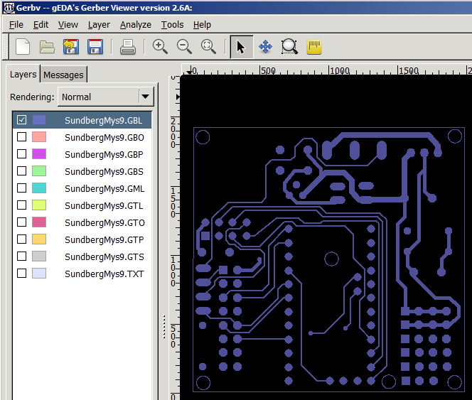
Yes, but this is Eagles output gerber files.Drill: SundbergMys9.TXT
Outline can be found in all other files:https://www.pcbway.com/project/share/How_to_generate_Gerber_from_Eagle.html
-
Damn. Just missing the 0,1uF capacitor ..... to complete the 5v build. This will be my smallest build yet ;-) using PCB v9
-
IS it possible to use TP4056 (https://www.aliexpress.com/item/5-pcs-Micro-USB-5V-1A-18650-TP4056-Lithium-Battery-Charger-Module-Charging-Board-With-Protection/32728720869.html?spm=a2g0s.9042311.0.0.A0lkC7) this instead of using the step up booster?
Thanks!! -
IS it possible to use TP4056 (https://www.aliexpress.com/item/5-pcs-Micro-USB-5V-1A-18650-TP4056-Lithium-Battery-Charger-Module-Charging-Board-With-Protection/32728720869.html?spm=a2g0s.9042311.0.0.A0lkC7) this instead of using the step up booster?
Thanks!!@hiddenuser - well not out of the box as mentioned by gohan. Im not really sure what you want to do. Its not possible to use this instead of step-up booster since it outputs 5v and the step-up needs to output 3.3v. But with a voltage regulator in between maybe? As I said - don really understand so maybe you can explain some more about your project?
Controller: Proxmox VM - Home Assistant
MySensors GW: Arduino Uno - W5100 Ethernet, Gw Shield Nrf24l01+ 2,4Ghz
MySensors GW: Arduino Uno - Gw Shield RFM69, 433mhz
RFLink GW - Arduino Mega + RFLink Shield, 433mhz -
@hiddenuser - well not out of the box as mentioned by gohan. Im not really sure what you want to do. Its not possible to use this instead of step-up booster since it outputs 5v and the step-up needs to output 3.3v. But with a voltage regulator in between maybe? As I said - don really understand so maybe you can explain some more about your project?
-
Thanks @sundberg84 and @gohan
I have used made the board for 3.3v set up as per the instruction. I have usd the output from tp4056 into the Battery connector of the board I have a step board from https://www.aliexpress.com/item/New-Electric-Unit-1-PC-NEW-DC-0-8-3-3V-to-DC-3-3V-StepUP/32724361266.html According to the specification given in the same link it is supposed to stabilize to 3.3v above 3v but the sensor reports something else back to the gateway.
@hiddenuser - well, what would a battery measurer be if it reported a constant 3.3v boosted voltage? ;)
It all depends on how everything is connected (pictures?) but if you have connected it as battery instryctions the radio and voltage divider that measured the incoming battery are not a part of the booster circuit. This to prevent noice to the radio and to be able to actually measure the battery voltage and not step-up voltage which is the idea behind the board. -
Thanks @sundberg84 and @gohan
I have used made the board for 3.3v set up as per the instruction. I have usd the output from tp4056 into the Battery connector of the board I have a step board from https://www.aliexpress.com/item/New-Electric-Unit-1-PC-NEW-DC-0-8-3-3V-to-DC-3-3V-StepUP/32724361266.html According to the specification given in the same link it is supposed to stabilize to 3.3v above 3v but the sensor reports something else back to the gateway.