NRF24L01+PA+LNA power consumption
-
@parachutesj as Jokgi said, you can't measure correctly the current of the modules with just a multimeter, you are losing peaks in the process.
Did you tried yet how far the shielded versions of the module reach? Would be great to have some sort of comparision. :+1: -
@parachutesj as Jokgi said, you can't measure correctly the current of the modules with just a multimeter, you are losing peaks in the process.
Did you tried yet how far the shielded versions of the module reach? Would be great to have some sort of comparision. :+1:@Oitzu
I do not have the equipment to measure the reach, I just noticed that some spots in the house seem to be covered which haven't been before. However this might be just because of different antenna placement. -
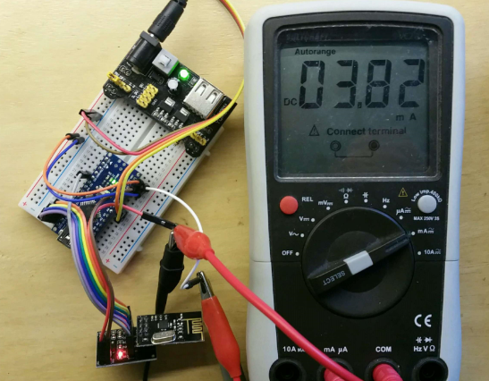
To demonstrate what happens I made some measurements on the NRF24L01+PA+LNA power consumption. The nano in the setup runs a simple sketch which sends one value every 100ms and sleeps in between (RF24_PA_MAX).
First is the setup with a standard nRF24L01+ (working clone ;-) ) The current meter measures the current in the power line of the radio (before the regulator to avoid side effects) and has an internal resistance of 3.4 Ohm. The measured current is a kind of random average sample and shows around 4 mA.
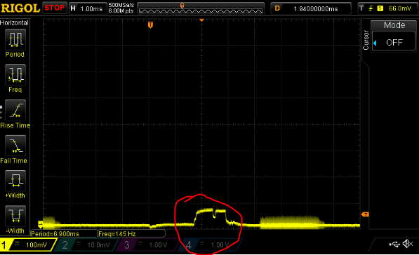
Now look at the waveform of the same current on the scope. I circled the radio send current. The level of pulse is around 70mV which translates to ~20mA (0.07 V/ 3.4 Ohm)
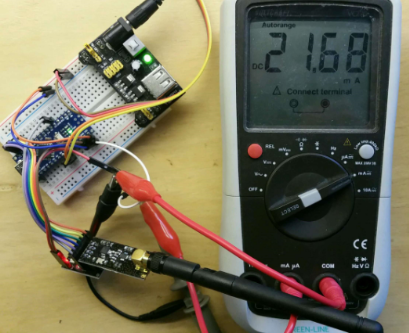
Second is the setup with a the nRF24L01+PA+LNA(working clone ;-) )
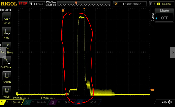
and the waveform on the scope.. around 700mV translates to ~200mA (0.7V/ 3.4.Ohm) 10 times as much and no comparison to the (random average sample) reading on the current meter of ~22mA (a Fluke meter does not change this ;-))
-
@Oitzu said:
https://www.squirrel-labs.net/wp/wp-content/uploads/2015/02/nRFa.jpg
Guys,
I also use the base module to connect my NRF24 radios, I recently received 2 of the shielded PA+LNB modules but don't see much difference using them. The issue I have is that I need to hold the module for it to be reliable :( Once I let go, the transmission slows and becomes unreliable (I experienced the same with the unshielded modules).
Is the base module okay to use wit the PA+LNB modules, I was concerned that someone said the module cannot use 5v control lines?
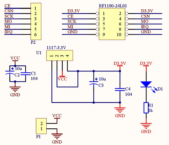
@Mark-Swift The "base plate" gives you a solid 3.3v for the radio and sufficient decouple/ bypass capacitors. i recognized there is a lot of variety in all kinds of radiio's even if these look similar. That's the reason I built this meter.
For shielding make sure you connect the shield to ground. A lot has been published on performance of these modules. -
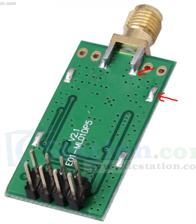
I'm using these modules, I presume the base unit is compatible? I was confused when I read above that the PA modules may need a 3v control line.
http://www.icstation.com/22dbm-100mw-nrf24l01ppalna-wireless-transmission-module-p-4677.html
I'm really frustrated that none of my modules work unless I physically hold them, even the shielded ones above!
-
I'm using these modules, I presume the base unit is compatible? I was confused when I read above that the PA modules may need a 3v control line.
http://www.icstation.com/22dbm-100mw-nrf24l01ppalna-wireless-transmission-module-p-4677.html
I'm really frustrated that none of my modules work unless I physically hold them, even the shielded ones above!
@Mark-Swift High frequency transmission is a kind of dark science... ;-) I had the same experience you had with the 'expensive' shileded modules. The best performance upto now I have with my own shielding on the PA modules (plastic and aluminum tape/foil) powered by the adapter board and connected to a stable 5v supply.
-
@Mark-Swift and @AWI i never worked with the adapter board, but doesn't shift the adapter board also the signal levels down?
@Mark-Swift need to hold the module is often a sign for non solid shielding or the shield is not grounded.
Out of courosity what power supply are you using in front of the adapter board? -
@Mark-Swift well.. maybe you should give the module a little bit more current. :)
I don't know which regulator the Uno uses but i would assume that it don't deliver enough current.About the grounding.. better be sure, take your multimeter and check if the shielding has continuity to GND.
@AWI ah okay... well.. i'm still unsure if and which modules need the lower 3.3V level on CE.
It just happens that i only use 3.3V arduinos.. and the raspberry pi, which also has 3.3V logic. -
I'm using these modules, I presume the base unit is compatible? I was confused when I read above that the PA modules may need a 3v control line.
http://www.icstation.com/22dbm-100mw-nrf24l01ppalna-wireless-transmission-module-p-4677.html
I'm really frustrated that none of my modules work unless I physically hold them, even the shielded ones above!
@Mark-Swift
I received two of them a few days ago and both work very well. I soldered a cap onto it as suggested and pointing the antenna straight up (aligned with Z axis)
One is just powered by an original Uno and the other via liniar power regulator. Not saying that this is enough, just in my case it is stable since Friday (3-4 days) -
@Mark-Swift
I received two of them a few days ago and both work very well. I soldered a cap onto it as suggested and pointing the antenna straight up (aligned with Z axis)
One is just powered by an original Uno and the other via liniar power regulator. Not saying that this is enough, just in my case it is stable since Friday (3-4 days)Strange, how are you driving them, what volt control line, 5v?
-
@Oitzu I presume the shielded modules from IC station would be spot on with regards shielding?
Right now I have my base module connected the 5v line of my Uno...?
@Mark-Swift The ones you refer are shielded.. as far as I can see.
So next level in debugging... how is you ground connected,. You can try to power the adapter plate from the supply of your UNO. The on board LM1117 should be able to accept upto 20V.
-
Strange, how are you driving them, what volt control line, 5v?
@Mark-Swift
no 3.3V.
However as said, it is an original Uno. I have clones which deliver no clean or reliable signal. I measured it before but don't remember exactly but was quite off. -
@Mark-Swift
no 3.3V.
However as said, it is an original Uno. I have clones which deliver no clean or reliable signal. I measured it before but don't remember exactly but was quite off.@parachutesj said:
@Mark-Swift
no 3.3V.
However as said, it is an original Uno. I have clones which deliver no clean or reliable signal. I measured it before but don't remember exactly but was quite off.The Uno has 5v control lines doesn't it?
-
@parachutesj said:
@Mark-Swift
no 3.3V.
However as said, it is an original Uno. I have clones which deliver no clean or reliable signal. I measured it before but don't remember exactly but was quite off.The Uno has 5v control lines doesn't it?
@Mark-Swift
the digital ports? AFAIK yes.
the radio VCC is connected to 3.3 (all to the pins as in the tutorial GND, VCC 3.3, D9-D13)
The other setup is via external power (ipad USB-Adapter) to a breadboard, VIN directly from 5V to the Arduino and another line via 3.3V regulator to the NRF24 radio. all other lines again directly connected to the arduino. -
@Mark-Swift The ones you refer are shielded.. as far as I can see.
So next level in debugging... how is you ground connected,. You can try to power the adapter plate from the supply of your UNO. The on board LM1117 should be able to accept upto 20V.
@AWI Ground is connected from the baseboard back to the Uno, along with the VCC. That's how I'm currently powering it, 5V from uno into the adaptor plate. All other control lines directly into the Uno.
-
hackaday caught wind on the tinfoil method.
http://hackaday.com/2016/05/31/fixing-the-terrible-range-of-your-cheap-nrf24l01-palna-module/
Maybe there also some points hidden in the comments that would help? -
I saw this on Hackaday, could we make this change in MySensors?
"Don’t use polling over SPI to check if there is a received packet like most of the libs out there do. This increases the noise. Use the IRQ pin"