NRF24L01+PA+LNA power consumption


  • Hi,
    I have ordered two of the PA radios from the linked store on ebay. My intention was to get the range a bit extended. I saw that there is probably not so much gain indoors, anyway I am playing around and try to get the best settings.

    So I connected to a Nano with power regulator LD1117 which should be capable of providing 800mA and with a regulated power supply which is rated for 2A.
    Connected the radio and measured the consumption which is never higher than around 23mA - I am wondering how the code needs to look like. This is my code:

    
    // NRFRF24L01 radio driver (set low transmit power by default)
    MyTransportNRF24 radio(RF24_CE_PIN, RF24_CS_PIN, RF24_PA_MAX);
    //MyTransportRFM69 radio;
    // Message signing driver (none default)
    //MySigningNone signer;
    // Select AtMega328 hardware profile
    MyHwATMega328 hw;
    // Construct MySensors library
    MySensor gw(radio, hw);


    No differences changing it from RF24_PA_LOW _HIGH or _MAX

    And here is my setup:
    alt text

    Will I only see differences in power consumption if it is under load?

    Thanks,
    SJ


  • Hi @parachutesj,

    you should test it with a loop sending data. It has the highest consumption while sending data.
    Seeing your PA/LNA you should also shield it, to extend range.


  • @Oitzu
    ok, will try pushing as much data as possible through the wire.
    I also tried the shielding with no differences to be honest.


  • @Oitzu
    I tried it with sending a lot of packets but still, no more current than before. Are there any specific settings I need to do for the PA radio?


  • @parachutesj: expect the RF24_PA_MAX no. I need to say that i still use the 1.5 library and set the PA_MAX setting in the MyConfig.h.


  • @Oitzu thank you. tried this as well with no difference. I suspect my radios are really bad. I got much better results with the non amplified ones during testing. I think I will try if they perform better with a LC filter if not, good bye


  • @parachutesj you probably don't benefit from a LC-Filter that much, because you are already using a linear regulator (LD1117 ).
    Make sure that you used the shielding right and grounded it.


  • What is the PA used on the board? Are there schematics available? (Or a part number for the board) Are they using the VDD_PA line from the nRF24L01P to enable the PA? If so, scope out the VDD_PA line and see if it is toggling when transmitting. It will go high 50us before the nRF24L01p transmits a packet and will stay high the full time it is transmitting. If that line is not toggling when sending packets then you are not transmitting.


  • @Jokgi: https://www.squirrel-labs.net/wp/wp-content/uploads/2015/02/nRFa.jpg
    I think that is what most of the boards are doing. But i also seen schematics in wich the 1kOhm resistor isn't there.
    So there could maybe be problems if you try to control the nrf24l01+ PA/LNA with a 5V Arduino because the PA can't handle the 5V signal.


  • @Oitzu
    Is that the released schematic for that Module?
    I can see why they have the resistor removed.
    The CE line is a active high input to the nRF24L01P. The RXEN is a input to the RFX2401C used to switch in the different modes. (See the mode select table below)
    The CE line could / should be controlled by the host MCU. You can see this on the state machine in the nRF24L01P datasheet section 6.1.1, Figure 4. The diagram shows recommended operating modes vs. possible operating modes.

    For the RFX2401C,,,,
    If the RXEN is pulled high with a resistor and when the nRF24L01P is not transmitting, the unit will switch the LNA in. In this setup the RFX never goes to shut down mode and the RFX is either in TX or RX mode. There are no internal pull ups or pull downs on the nRF24L01P CE or or the RFX devices RXEN. Therefore there is no guaranty that the lines will be high or low and could be subject to noise. I would not leave them floating.

    Control Logic Truth Table X= Don't Care
    TXEN RXEN 0perating Conditions
    1 X TX Active
    0 1 RX Active
    0 0 Chip is Shut-down

    To address the Current Draw. According to the RFX2401C datasheet, when the PA is transmitting at 20dBm the current consumption of the amp is 120mA. Plus whatever else you have running. (MCU, nRF24L01P, etc)


  • @Jokgi hard to say to which module excatly it belongs.. would need to track the traces on the pcb to be 100% sure.
    Isn't CE pulled down by the MCU while not transmitting or receiving? I do not have really any problems with the module going power down.

    @parachutesj Well i got most problems with this sort of module, if you have the one pictured.
    They tended to not run at all without adding a grounded shield, add the LC-Filer and maked sure to run the signals with 3.3V.


  • @Oitzu The pictures I have seen of various PA modules available on EBAY and such show a pretty solid ground pour on the top and bottom of the module. I am surprised that wrapping them with Au foil helped much. (But stranger things have been known to work. ๐Ÿ˜‰ ) Does anyone have some quantitative numbers with and without the foil mods?


  • @Jokgi @ all. Sorry I was not specific. I should have added Range measurements with and without the foil.


  • @Jokgi it may be true that the ground filling seems to be quite good, but it seems like it needs also be shielded.
    Without the shielding the module is influenced by its own signals and external signals.
    There are also modules out there that have actually a shield added: http://www.aliexpress.com/item/Shielding-Case-10pcs-lot-nRF24L01-PA-LNA-wireless-communication-modules-with-antenna-2-4GHz-2Mbps-1000m/851058052.html
    But i have not tested them yet.

    By quantitative numbers you mean range?
    On max transmitting power i don't got even 5meters because the PA TX seems to overload the RX and ack will never be received.
    With the shielding i got arround 1000 meters free line of sight.


  • @Oitzu
    I got the new ones in the mail today. those are the shielded ones from IC station (http://www.icstation.com/22dbm-100mw-nrf24l01ppalna-wireless-transmission-module-p-4677.html)
    but even here when measuring current it never goes higher than 31mA
    I am going nuts. I mean I should be happy about the low power consumption but I think I haven't set them up correctly and not getting the full power.

    Again, I set in MyConfig.h

    #define RF24_PA_LEVEL 	   RF24_PA_MAX
    #define RF24_PA_LEVEL_GW   RF24_PA_MAX
    

    and my constructor:

    MyTransportNRF24 radio(RF24_CE_PIN, RF24_CS_PIN, RF24_PA_LEVEL);
    

    I am measuring with a Fluke 87V and just making sure also took another one reading similar values.
    I ran the VCC through my multimeter - any ideas?


  • @parachutesj i'm reading pretty much the same values on my multimeter, so nothing to worry about. ๐Ÿ˜‰


  • @Oitzu I just thougt that others reported 115mA and more.
    However the module with the shielding says 100mW that would make at 3.3v exactly 30.3 mA... So actually yes, all correct


  • @Oitzu Thanks for the follow up. Yes, the CE line is a input to the nRF24L01P. In the schematic sent yesterday it showed the CE line connected to the RXEN of the RFX2401c. Both are inputs.


  • @parachutesj Unless you have the transmitter in constant carrier mode you cannot successfully measure the current with a standard multi-meter. If you want to know if the radio is transmitting and you have a good scope then look at the VDD_PA line.


  • @parachutesj as Jokgi said, you can't measure correctly the current of the modules with just a multimeter, you are losing peaks in the process.
    Did you tried yet how far the shielded versions of the module reach? Would be great to have some sort of comparision. ๐Ÿ‘


  • @Oitzu
    I do not have the equipment to measure the reach, I just noticed that some spots in the house seem to be covered which haven't been before. However this might be just because of different antenna placement.


  • Hero Member

    To demonstrate what happens I made some measurements on the NRF24L01+PA+LNA power consumption. The nano in the setup runs a simple sketch which sends one value every 100ms and sleeps in between (RF24_PA_MAX).

    First is the setup with a standard nRF24L01+ (working clone ๐Ÿ˜‰ ) The current meter measures the current in the power line of the radio (before the regulator to avoid side effects) and has an internal resistance of 3.4 Ohm. The measured current is a kind of random average sample and shows around 4 mA.

    0_1464463953266_upload-0a19ffdd-3807-4724-9fd1-c809b69bff96

    Now look at the waveform of the same current on the scope. I circled the radio send current. The level of pulse is around 70mV which translates to ~20mA (0.07 V/ 3.4 Ohm)
    0_1464464509368_upload-399190d7-d122-4ebe-b88b-a2b4352eb726

    Second is the setup with a the nRF24L01+PA+LNA(working clone ๐Ÿ˜‰ )
    0_1464464861402_upload-ea2156f5-3315-47a3-9568-62d1aa6b7687

    and the waveform on the scope.. around 700mV translates to ~200mA (0.7V/ 3.4.Ohm) 10 times as much and no comparison to the (random average sample) reading on the current meter of ~22mA (a Fluke meter does not change this ;-))

    0_1464465244455_upload-12912f74-4dfb-467a-9ae9-c0990c26eb50


  • @Oitzu said:

    https://www.squirrel-labs.net/wp/wp-content/uploads/2015/02/nRFa.jpg

    Guys,

    I also use the base module to connect my NRF24 radios, I recently received 2 of the shielded PA+LNB modules but don't see much difference using them. The issue I have is that I need to hold the module for it to be reliable ๐Ÿ˜ž Once I let go, the transmission slows and becomes unreliable (I experienced the same with the unshielded modules).

    Is the base module okay to use wit the PA+LNB modules, I was concerned that someone said the module cannot use 5v control lines?


  • Hero Member

    @Mark-Swift The "base plate" gives you a solid 3.3v for the radio and sufficient decouple/ bypass capacitors. i recognized there is a lot of variety in all kinds of radiio's even if these look similar. That's the reason I built this meter.
    For shielding make sure you connect the shield to ground. A lot has been published on performance of these modules.


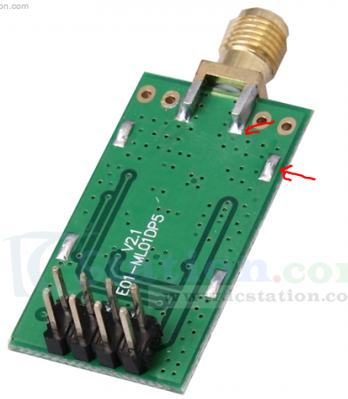
  • I'm using these modules, I presume the base unit is compatible? I was confused when I read above that the PA modules may need a 3v control line.

    http://www.icstation.com/22dbm-100mw-nrf24l01ppalna-wireless-transmission-module-p-4677.html

    I'm really frustrated that none of my modules work unless I physically hold them, even the shielded ones above!


  • Hero Member

    @Mark-Swift High frequency transmission is a kind of dark science... ๐Ÿ˜‰ I had the same experience you had with the 'expensive' shileded modules. The best performance upto now I have with my own shielding on the PA modules (plastic and aluminum tape/foil) powered by the adapter board and connected to a stable 5v supply.


  • @Mark-Swift and @AWI i never worked with the adapter board, but doesn't shift the adapter board also the signal levels down?

    @Mark-Swift need to hold the module is often a sign for non solid shielding or the shield is not grounded.
    Out of courosity what power supply are you using in front of the adapter board?


  • @Oitzu I presume the shielded modules from IC station would be spot on with regards shielding?

    Right now I have my base module connected the 5v line of my Uno...?


  • Hero Member

    @Oitzu nothing fancy on the adapter board other than a LDO and decoupling (and a LED).

    0_1464695559079_upload-015c7695-c390-4466-aee0-6d242f64defe

    be aware that the schematic is for the 10p version of the nRf24


  • @Mark-Swift well.. maybe you should give the module a little bit more current. ๐Ÿ™‚
    I don't know which regulator the Uno uses but i would assume that it don't deliver enough current.

    About the grounding.. better be sure, take your multimeter and check if the shielding has continuity to GND.

    @AWI ah okay... well.. i'm still unsure if and which modules need the lower 3.3V level on CE.
    It just happens that i only use 3.3V arduinos.. and the raspberry pi, which also has 3.3V logic.


  • @Mark-Swift
    I received two of them a few days ago and both work very well. I soldered a cap onto it as suggested and pointing the antenna straight up (aligned with Z axis)
    One is just powered by an original Uno and the other via liniar power regulator. Not saying that this is enough, just in my case it is stable since Friday (3-4 days)


  • @parachutesj

    Strange, how are you driving them, what volt control line, 5v?


  • Hero Member

    @Mark-Swift The ones you refer are shielded.. as far as I can see.
    0_1464696145069_upload-6475afd2-f07a-496f-be95-a8f71187f6cd

    So next level in debugging... how is you ground connected,. You can try to power the adapter plate from the supply of your UNO. The on board LM1117 should be able to accept upto 20V.


  • @Mark-Swift
    no 3.3V.
    However as said, it is an original Uno. I have clones which deliver no clean or reliable signal. I measured it before but don't remember exactly but was quite off.


  • @parachutesj said:

    @Mark-Swift
    no 3.3V.
    However as said, it is an original Uno. I have clones which deliver no clean or reliable signal. I measured it before but don't remember exactly but was quite off.

    The Uno has 5v control lines doesn't it?


  • @Mark-Swift
    the digital ports? AFAIK yes.
    the radio VCC is connected to 3.3 (all to the pins as in the tutorial GND, VCC 3.3, D9-D13)
    The other setup is via external power (ipad USB-Adapter) to a breadboard, VIN directly from 5V to the Arduino and another line via 3.3V regulator to the NRF24 radio. all other lines again directly connected to the arduino.


  • @AWI Ground is connected from the baseboard back to the Uno, along with the VCC. That's how I'm currently powering it, 5V from uno into the adaptor plate. All other control lines directly into the Uno.


  • hackaday caught wind on the tinfoil method.
    http://hackaday.com/2016/05/31/fixing-the-terrible-range-of-your-cheap-nrf24l01-palna-module/
    Maybe there also some points hidden in the comments that would help?


  • I saw this on Hackaday, could we make this change in MySensors?

    "Donโ€™t use polling over SPI to check if there is a received packet like most of the libs out there do. This increases the noise. Use the IRQ pin"

    @hek


  • Admin

    In the development branch we do use irq nowadays, if you define

    #define MY_RF24_IRQ_PIN xx

    It also de-queues messages from the NRF24 quickly, which reduces missed messages.


  • @hek amazing, I never knew that.

    So all I would do is define this line in my sketch and connect up the IRQ line?

    I presume I can use this on both my gateway (ESP8266) and my nodes (Nano / Uno)?


  • Admin

    The ESP still doesn't support this feature due to lack of SPI transaction support (if I remember correctly? @Yveaux ).


  • Mod

    @hek @Mark-Swift More precisely, it misses the interrupt protection for SPI transfers. Ref https://github.com/esp8266/Arduino/issues/1943.

    But the queueing is not yet in development, as far as I know -- it is in my personan testing branch https://github.com/Yveaux/Arduino/tree/development_rxqueue


  • @Mark-Swift there are basicly effects that could occur while you holding the module:
    1.) You are forming a very small capacitor between you and the module.
    Much unlikely to be the reason.
    2.) You are functioning as an antenna for the module.
    Also much unlikely, you would probably bring more noise then signal in the system.
    3.) You function as a shield to the module.
    More likely. I got the same behavior with insufficient shielding.
    The shielding works ungrounded in low noise environment but needs to be grounded in a high noise environment.
    This happens, as example, if a insufficient shielded switching power supply is nearby.

    Please make absolutely sure that your shield is properly grounded!


  • @Oitzu The shielded modules appear to have the shield well grounded?


  • @Mark-Swift does "appear" mean you actually measured it all the way to ground or that you believe that it should be well grounded?


  • Hardware Contributor

    @hek
    So it would make sense to connect the IRQ pin of the radio to the processor ? Any pin ? Or is it meant for INT0/INT1 pins only ?


  • @GertSanders Did you find an answer to this? With 2.0.0 would it be better to use IRQ now? Just connecting the pin and adding the IRQ line?


  • Mod

    @karl261 It isn't used by default in 2.0.0, but can be used in the 2.0.1 development brach. I would advise you to connect the nRF irq pin to into (pin 2), to be prepared for later usage.


  • @Yveaux So, basically this means that in the future we can have the arduino sleeping and when a message comes in it wakes up from the interrupt? Sounds like repeaters could run on battery then. If there is not too much traffic.


  • Admin

    No, running repeaters on battery is probably not possible. Keeping radio in listening-mode takes too much juice.


  • @hek Ah yes, that's right. The radio needs to be on. I forgot about that. We need an over the air interrupt... ๐Ÿ˜‰


Log in to reply
 

Suggested Topics

  • 3
  • 24
  • 2
  • 1
  • 2
  • 2

24
Online

11.2k
Users

11.1k
Topics

112.5k
Posts