ESP + RFM69 Gateway Reset issue
-
Hi all,
Firstly I'm so impressed with the community and the development on MySensors, it's great how the whole DIY IoT thing has boomed over the past couple of years.
I'm trying to get the ESP Gateway example working with a RFM69 radio and having some issues it connects to my Wifi network fine, then fails shortly afterwards, at the same point every time. I've included a dump of the Serial from one full iteration and also a quick photo (though it's not that clear with all the wires) of my setup. Suffice to say it's basically just a normal ESP12 setup connected to the RFM69 as the documentation says.
I'm using the latest versions of everything also.
If anyone has any ideas they would be really appreciated.Starting gateway (RRNGE-, 2.0.0) 0;255;3;0;9;TSM:INIT scandone state: 0 -> 2 (b0) 0;255;3;0;9;!TSM:RADIO:FAIL 0;255;3;0;9;!TSM:FAILURE 0;255;3;0;9;TSM:PDT state: 2 -> 0 (2) reconnect f 0, scandone state: 0 -> 2 (b0) state: 2 -> 3 (0) state: 3 -> 5 (10) add 0 aid 3 cnt connected with xxxxxxxxxxxxxxx, channel 1 dhcp client start... ip:192.168.0.18,mask:255.255.255.0,gw:192.168.0.1 0;255;3;0;9;TSM:INIT Soft WDT reset ctx: cont sp: 3fff00f0 end: 3fff03e0 offset: 01b0 >>>stack>>> 3fff02a0: 00000004 00000000 3fff0480 4020221c 3fff02b0: 00000027 3fff06f4 3fff0480 40202861 3fff02c0: 3fff0498 00000001 3fff0480 402029a5 3fff02d0: 00000000 00000016 3fff0480 40202be0 3fff02e0: 0000002f 3fff06f4 3fff0480 000000ff 3fff02f0: 00000000 00000016 3fff0480 40203d39 3fff0300: 00020401 40040203 33060305 0008d907 3fff0310: 42190009 07264025 dc291028 2d2f882e 3fff0320: 90376430 8f3c4238 306f123d 3fff00ff 3fff0330: 00000064 00000004 3fff0480 40202994``` -
Hey,
Yea it's the ESP8266 Gateway sketch, unmodified except for the various defines I'd need afaik./** * The MySensors Arduino library handles the wireless radio link and protocol * between your home built sensors/actuators and HA controller of choice. * The sensors forms a self healing radio network with optional repeaters. Each * repeater and gateway builds a routing tables in EEPROM which keeps track of the * network topology allowing messages to be routed to nodes. * * Created by Henrik Ekblad <henrik.ekblad@mysensors.org> * Copyright (C) 2013-2015 Sensnology AB * Full contributor list: https://github.com/mysensors/Arduino/graphs/contributors * * Documentation: http://www.mysensors.org * Support Forum: http://forum.mysensors.org * * This program is free software; you can redistribute it and/or * modify it under the terms of the GNU General Public License * version 2 as published by the Free Software Foundation. * ******************************* * * REVISION HISTORY * Version 1.0 - Henrik EKblad * Contribution by a-lurker and Anticimex, * Contribution by Norbert Truchsess <norbert.truchsess@t-online.de> * Contribution by Ivo Pullens (ESP8266 support) * * DESCRIPTION * The EthernetGateway sends data received from sensors to the WiFi link. * The gateway also accepts input on ethernet interface, which is then sent out to the radio network. * * VERA CONFIGURATION: * Enter "ip-number:port" in the ip-field of the Arduino GW device. This will temporarily override any serial configuration for the Vera plugin. * E.g. If you want to use the defualt values in this sketch enter: 192.168.178.66:5003 * * LED purposes: * - To use the feature, uncomment any of the MY_DEFAULT_xx_LED_PINs in your sketch, only the LEDs that is defined is used. * - RX (green) - blink fast on radio message recieved. In inclusion mode will blink fast only on presentation recieved * - TX (yellow) - blink fast on radio message transmitted. In inclusion mode will blink slowly * - ERR (red) - fast blink on error during transmission error or recieve crc error * * See http://www.mysensors.org/build/esp8266_gateway for wiring instructions. * nRF24L01+ ESP8266 * VCC VCC * CE GPIO4 * CSN/CS GPIO15 * SCK GPIO14 * MISO GPIO12 * MOSI GPIO13 * GND GND * * Not all ESP8266 modules have all pins available on their external interface. * This code has been tested on an ESP-12 module. * The ESP8266 requires a certain pin configuration to download code, and another one to run code: * - Connect REST (reset) via 10K pullup resistor to VCC, and via switch to GND ('reset switch') * - Connect GPIO15 via 10K pulldown resistor to GND * - Connect CH_PD via 10K resistor to VCC * - Connect GPIO2 via 10K resistor to VCC * - Connect GPIO0 via 10K resistor to VCC, and via switch to GND ('bootload switch') * * Inclusion mode button: * - Connect GPIO5 via switch to GND ('inclusion switch') * * Hardware SHA204 signing is currently not supported! * * Make sure to fill in your ssid and WiFi password below for ssid & pass. */ // Enable debug prints to serial monitor #define MY_DEBUG // Use a bit lower baudrate for serial prints on ESP8266 than default in MyConfig.h #define MY_BAUD_RATE 9600 // Enables and select radio type (if attached) //#define MY_RADIO_NRF24 #define MY_RADIO_RFM69 #define MY_RFM69_FREQUENCY RF69_433MHZ #define MY_IS_RFM69HW #define MY_GATEWAY_ESP8266 #define MY_ESP8266_SSID "xxxxx" #define MY_ESP8266_PASSWORD "xxxxx" // Enable UDP communication //#define MY_USE_UDP // Set the hostname for the WiFi Client. This is the hostname // it will pass to the DHCP server if not static. #define MY_ESP8266_HOSTNAME "sensor-gateway" // Enable MY_IP_ADDRESS here if you want a static ip address (no DHCP) //#define MY_IP_ADDRESS 192,168,178,87 // If using static ip you need to define Gateway and Subnet address as well //#define MY_IP_GATEWAY_ADDRESS 192,168,178,1 //#define MY_IP_SUBNET_ADDRESS 255,255,255,0 // The port to keep open on node server mode #define MY_PORT 5003 // How many clients should be able to connect to this gateway (default 1) #define MY_GATEWAY_MAX_CLIENTS 2 // Controller ip address. Enables client mode (default is "server" mode). // Also enable this if MY_USE_UDP is used and you want sensor data sent somewhere. //#define MY_CONTROLLER_IP_ADDRESS 192, 168, 178, 68 // Enable inclusion mode //#define MY_INCLUSION_MODE_FEATURE // Enable Inclusion mode button on gateway // #define MY_INCLUSION_BUTTON_FEATURE // Set inclusion mode duration (in seconds) //#define MY_INCLUSION_MODE_DURATION 60 // Digital pin used for inclusion mode button //#define MY_INCLUSION_MODE_BUTTON_PIN 3 // Set blinking period // #define MY_DEFAULT_LED_BLINK_PERIOD 300 // Flash leds on rx/tx/err // Led pins used if blinking feature is enabled above #define MY_DEFAULT_ERR_LED_PIN 16 // Error led pin #define MY_DEFAULT_RX_LED_PIN 16 // Receive led pin #define MY_DEFAULT_TX_LED_PIN 16 // the PCB, on board LED #if defined(MY_USE_UDP) #include <WiFiUdp.h> #endif #include <ESP8266WiFi.h> #include <MySensors.h> void setup() { } void presentation() { // Present locally attached sensors here } void loop() { // Send locally attached sensors data here } -
Hey,
Yea it's the ESP8266 Gateway sketch, unmodified except for the various defines I'd need afaik./** * The MySensors Arduino library handles the wireless radio link and protocol * between your home built sensors/actuators and HA controller of choice. * The sensors forms a self healing radio network with optional repeaters. Each * repeater and gateway builds a routing tables in EEPROM which keeps track of the * network topology allowing messages to be routed to nodes. * * Created by Henrik Ekblad <henrik.ekblad@mysensors.org> * Copyright (C) 2013-2015 Sensnology AB * Full contributor list: https://github.com/mysensors/Arduino/graphs/contributors * * Documentation: http://www.mysensors.org * Support Forum: http://forum.mysensors.org * * This program is free software; you can redistribute it and/or * modify it under the terms of the GNU General Public License * version 2 as published by the Free Software Foundation. * ******************************* * * REVISION HISTORY * Version 1.0 - Henrik EKblad * Contribution by a-lurker and Anticimex, * Contribution by Norbert Truchsess <norbert.truchsess@t-online.de> * Contribution by Ivo Pullens (ESP8266 support) * * DESCRIPTION * The EthernetGateway sends data received from sensors to the WiFi link. * The gateway also accepts input on ethernet interface, which is then sent out to the radio network. * * VERA CONFIGURATION: * Enter "ip-number:port" in the ip-field of the Arduino GW device. This will temporarily override any serial configuration for the Vera plugin. * E.g. If you want to use the defualt values in this sketch enter: 192.168.178.66:5003 * * LED purposes: * - To use the feature, uncomment any of the MY_DEFAULT_xx_LED_PINs in your sketch, only the LEDs that is defined is used. * - RX (green) - blink fast on radio message recieved. In inclusion mode will blink fast only on presentation recieved * - TX (yellow) - blink fast on radio message transmitted. In inclusion mode will blink slowly * - ERR (red) - fast blink on error during transmission error or recieve crc error * * See http://www.mysensors.org/build/esp8266_gateway for wiring instructions. * nRF24L01+ ESP8266 * VCC VCC * CE GPIO4 * CSN/CS GPIO15 * SCK GPIO14 * MISO GPIO12 * MOSI GPIO13 * GND GND * * Not all ESP8266 modules have all pins available on their external interface. * This code has been tested on an ESP-12 module. * The ESP8266 requires a certain pin configuration to download code, and another one to run code: * - Connect REST (reset) via 10K pullup resistor to VCC, and via switch to GND ('reset switch') * - Connect GPIO15 via 10K pulldown resistor to GND * - Connect CH_PD via 10K resistor to VCC * - Connect GPIO2 via 10K resistor to VCC * - Connect GPIO0 via 10K resistor to VCC, and via switch to GND ('bootload switch') * * Inclusion mode button: * - Connect GPIO5 via switch to GND ('inclusion switch') * * Hardware SHA204 signing is currently not supported! * * Make sure to fill in your ssid and WiFi password below for ssid & pass. */ // Enable debug prints to serial monitor #define MY_DEBUG // Use a bit lower baudrate for serial prints on ESP8266 than default in MyConfig.h #define MY_BAUD_RATE 9600 // Enables and select radio type (if attached) //#define MY_RADIO_NRF24 #define MY_RADIO_RFM69 #define MY_RFM69_FREQUENCY RF69_433MHZ #define MY_IS_RFM69HW #define MY_GATEWAY_ESP8266 #define MY_ESP8266_SSID "xxxxx" #define MY_ESP8266_PASSWORD "xxxxx" // Enable UDP communication //#define MY_USE_UDP // Set the hostname for the WiFi Client. This is the hostname // it will pass to the DHCP server if not static. #define MY_ESP8266_HOSTNAME "sensor-gateway" // Enable MY_IP_ADDRESS here if you want a static ip address (no DHCP) //#define MY_IP_ADDRESS 192,168,178,87 // If using static ip you need to define Gateway and Subnet address as well //#define MY_IP_GATEWAY_ADDRESS 192,168,178,1 //#define MY_IP_SUBNET_ADDRESS 255,255,255,0 // The port to keep open on node server mode #define MY_PORT 5003 // How many clients should be able to connect to this gateway (default 1) #define MY_GATEWAY_MAX_CLIENTS 2 // Controller ip address. Enables client mode (default is "server" mode). // Also enable this if MY_USE_UDP is used and you want sensor data sent somewhere. //#define MY_CONTROLLER_IP_ADDRESS 192, 168, 178, 68 // Enable inclusion mode //#define MY_INCLUSION_MODE_FEATURE // Enable Inclusion mode button on gateway // #define MY_INCLUSION_BUTTON_FEATURE // Set inclusion mode duration (in seconds) //#define MY_INCLUSION_MODE_DURATION 60 // Digital pin used for inclusion mode button //#define MY_INCLUSION_MODE_BUTTON_PIN 3 // Set blinking period // #define MY_DEFAULT_LED_BLINK_PERIOD 300 // Flash leds on rx/tx/err // Led pins used if blinking feature is enabled above #define MY_DEFAULT_ERR_LED_PIN 16 // Error led pin #define MY_DEFAULT_RX_LED_PIN 16 // Receive led pin #define MY_DEFAULT_TX_LED_PIN 16 // the PCB, on board LED #if defined(MY_USE_UDP) #include <WiFiUdp.h> #endif #include <ESP8266WiFi.h> #include <MySensors.h> void setup() { } void presentation() { // Present locally attached sensors here } void loop() { // Send locally attached sensors data here }@OpticFroggy sorry for the late reply. I haven't used rfm radios before, but tonight I finally got it working, with a lot of help from @scalz and the rest of the MySensors team.
This is my wiring:
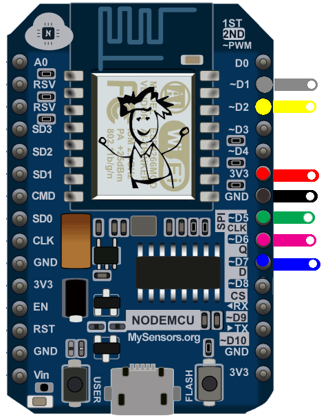
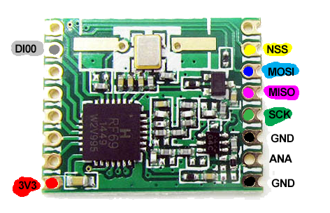
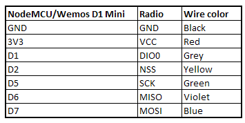
These are my settings in the sketch:
#define MY_RADIO_RFM69
#define MY_RFM69_FREQUENCY RF69_433MHZ
#define MY_IS_RFM69HW
#define MY_RF69_IRQ_PIN D1
#define MY_RF69_IRQ_NUM MY_RF69_IRQ_PIN
#define MY_RF69_SPI_CS D2 // NSS
D8 cannot be used because it interferes with uploading sketches.
With this, I got an nodemcu rfm69H-433 ethernet gateway working, and a wemos d1 mini rfm69H-433 sensor node. I used MySensors 2.1.1.

Hello! It looks like you're interested in this conversation, but you don't have an account yet.
Getting fed up of having to scroll through the same posts each visit? When you register for an account, you'll always come back to exactly where you were before, and choose to be notified of new replies (either via email, or push notification). You'll also be able to save bookmarks and upvote posts to show your appreciation to other community members.
With your input, this post could be even better 💗
Register Login