[SOLVED] Problems with Ethernet Gateway (Arduino Ethernet Shield)
-
@korttoma said:
... I had some similar problems when trying to use the PA+LNA radio module so I switched to a regular one and that one works fine. I wanted to use the PA+LNA version because the device is quite far from GW and I did not think the regular one could handle the distance but it did.
Coming back to this...
I recently changed over to the ethernet gateway (I could not get a stable serial connection Arduino-to-Vera) and am experiencing a little trouble.
I am using the Arduino Ethernet Shield with the WizNet chipset. with the NRF24L01+PA+LNA SMA Antenna Wireless Transceiver. MySensors version 1.4.
My problem is that I can initially get connection, great communication to the nodes...
Side note: I removed (unplugged) my PhoneyTV because I believe the base code that I am using, which creates a Relay Node, is affecting (disrupting) the communications from some of my nodes.
So, after about 15mins, the gateway stops communicating. I can ping it and it returns, so I know that ethernet communication is not likely the issue... Radio communication stops.
Could my problem be related to power required to drive the radio? Should I just use the regular radio module NRF24L01+ 2.4GHz Wireless RF Transceiver Module?
any advice appreciated...
-
Maybe you could test with a normal radio to see if the problem persists.
-
Will do... I am thinking that the power requirement for the antenna version may be more than my poor Uno can deliver...
-
Yes, most probably.
-
Might want to check:http://forum.mysensors.org/topic/466/ethernet-gateway-problem.
I had the same problem but after addressing SPIO and radio problems it's been rock steady over a week now. Had to use separate power supply for the antenna version.
-
Oh, and make sure you use 1.4.1 library.
-
Thanks, I didn't see any announcement re: 1.4.1, but it seems a few of the library files were indeed updated.
I'm gong to mess about with the lower power radio, but can you tell me how you powered your radio?
Also, what sketch did you end up with for the gateway with software SPI?
THANKS!!
-
I used a standard (cell phone type) 5V power supply and with the AMS1117 (listed in hardware) to knock it down to the 3.3V required by the radio. If your gateway (or sensor) works for a while and then stops and then will start again when plugged back in/rebooted you can almost bet it's a radio power problem (if you are already using soft SPI for your gateway).
Use the latest sketch from the 1.4.1 library for the gateway. The soft SPI stuff is included in the latest library. I just needs to be turned on by some include statement changes in the gateway and RF24_config.h. It requires changes in the radio wiring to the arduino also. I used the instructions provided by Anticimex that are contained in the link I posted above. It's a long thread but the instructions are in there. Probably needs to be broken out as a separate how to posting.
-
@Dan-S. said:
I used a standard (cell phone type) 5V power supply and with the AMS1117 (listed in hardware) to knock it down to the 3.3V required by the radio. If your gateway (or sensor) works for a while and then stops and then will start again when plugged back in/rebooted you can almost bet it's a radio power problem (if you are already using soft SPI for your gateway).
Use the latest sketch from the 1.4.1 library for the gateway. The soft SPI stuff is included in the latest library. I just needs to be turned on by some include statement changes in the gateway and RF24_config.h. It requires changes in the radio wiring to the arduino also. I used the instructions provided by Anticimex that are contained in the link I posted above. It's a long thread but the instructions are in there. Probably needs to be broken out as a separate how to posting.
Yeah,
The thread is so long, and after reading through it a few times, it is not possible for me to understand what I need to do to get this working.
I am using the latest library with the Ethernet Gateway sketch on github... but still not working

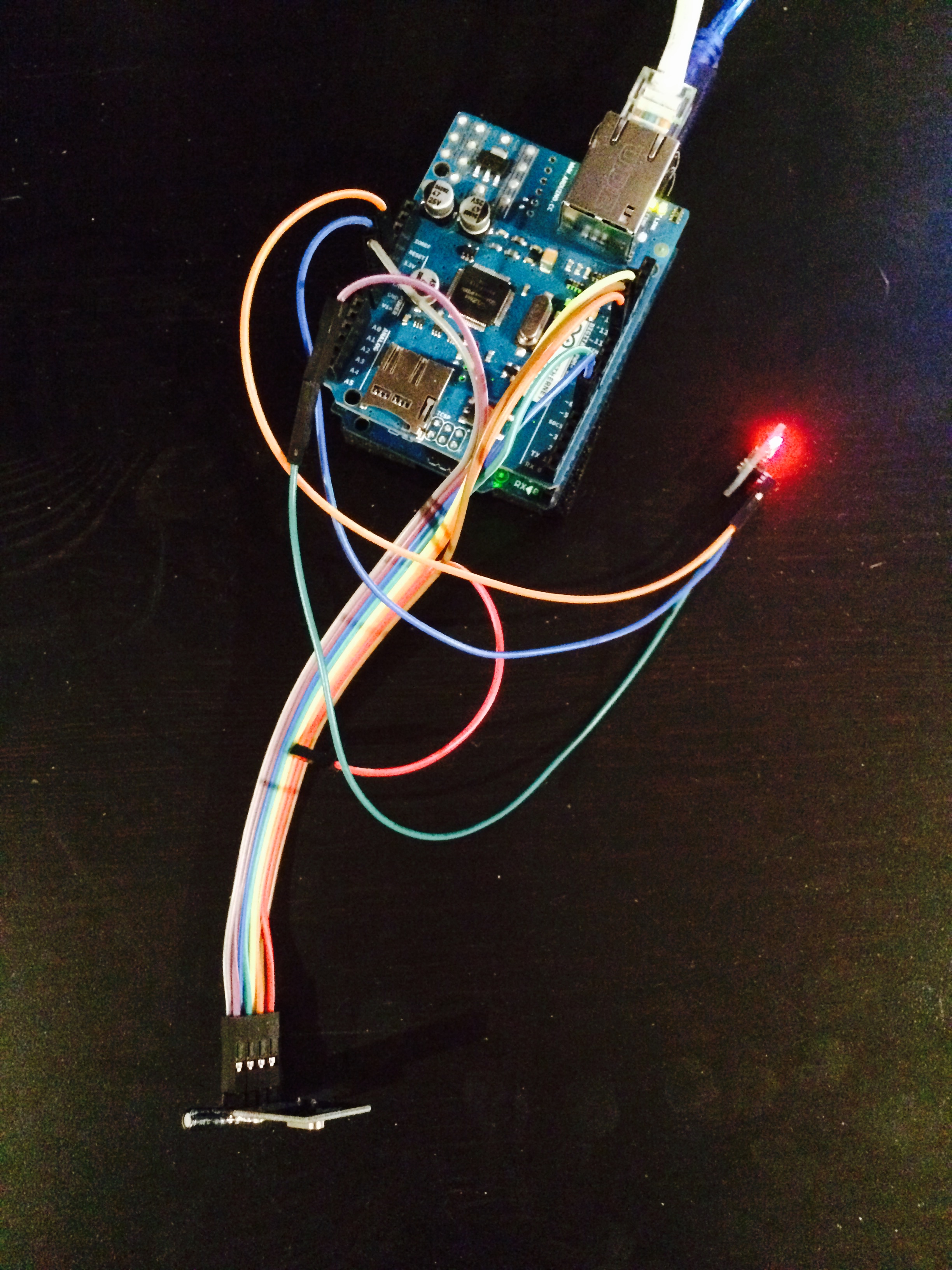
Here is a photo of my rig, separating the power supply for the radio.

-
I agree with @BulldogLowell . The description that @Anticimex did in the other thread is not easy to understand, at least I could not either. A write-up from someone that has actually done it would be greatly appreciated.
-
@korttoma what is unclear?
-
exit Arduino ide, download latest Master library 1.4.1
Patch file RF24_config.h (xxxx\MySensors\utility) to enable softspi,
uncomment (remove //) #define SOFTSPI
and change pin numbers as below:
const uint8_t SOFT_SPI_MISO_PIN = 15;
const uint8_t SOFT_SPI_MOSI_PIN = 14;
const uint8_t SOFT_SPI_SCK_PIN = 16;Connecto radio and gateway as per instructions for ethernet gateway except MISO, MOSI and SCK.
These connect as below
radio MOSI to arduino A0,
radio MISO to arduino A1,
radio SCK to arduino A2.start arudino ide 1.5.8, open Ethernet Gateway sketch and amend/add below lines
add this line: #include <DigitalIO.h>
comment UIPEthernet.h (//#include <UIPEthernet.h>)
uncomment Ethernet.h (#include <Ethernet.h>)
and choose IP address
-
@niccodemi Very good description of what needs to be done. Only addition I would make is that you have to undo the changes you made other than to the gateway sketch when you go back to creating sensors. May be just as easy to reload the library to do that.
-
@BulldogLowell You are not using the antenna version but since I am, I used an entirely separate 5 volt wall wart supply to power the radio through the AMS117--did not go through the UNO power as it looks like you did in the pix. Just need to make sure that all the grounds are common if you do like I did, i.e. connect the ground from the separate supply to the UNO/shield ground in addition to the AMS117 and radio ground.
-
@niccodemi said:
const uint8_t SOFT_SPI_MISO_PIN = 15;
const uint8_t SOFT_SPI_MOSI_PIN = 14;
const uint8_t SOFT_SPI_SCK_PIN = 16;and these are the correct pinouts for my Arduino Ethernet Shield, correct?
This is moving the SPI communication between the Uno and the shield off to another set of pins, and we are leaving the radio pins on hardware SPI?
Thanks!!!!
-
Apart from my question above, my only concern is how much power. It occurs to me that the radios attached to my sensor nodes NEVER have this problem, so it make me think that he Ethernet Shield consumes too much power... we got that. Is it the consensus that the power that Uno can provide is not enough to power the Radio and the Ethernet shield?
Thanks for the assistance, it is appreciated. Hope to get there soon!
-
@BulldogLowell Once you sent the pin definitions in RF24_config.h as you indicated you connect the MOSI, MISO and SCK pins of the radio to A0,A1 and A2 on the Ethernet shield/UNO as niccodemi indicated. The other radio pins remain connected as they were originally.
-
right, completely understood now. i updated my IDE, made all the edits, changed the pins and loaded up my rig.
fingers crossed.
Thanks for everyone's help!
-
-
@BulldogLowell said:
OK... Working fine

THANKS to everyone who assisted!!!
UPDATE: 12 hours and working perfectly!
-
Thanks @niccodemi for the detailed how to. Now to only thing unclear to me is if this can be applied on the Ethernet board I have or should I order a new one? I have built a Ethernet GW with a Pro mini and that Ethernet board but I just have not found time to take it in to use and then there was all this about the SPI issue that made me push the task ahead of me.
-
@korttoma , I don't see why it shouldn't work with your board. It doesn't cost you anything to try and report back here how it went.
-
@BulldogLowell , are you using relay actuators with your ethernet gw?
-
I'm not sure I know what you mean... Do you mean are some attached node used as relays?
Gateway still working perfectly...
-
@BulldogLowell yes, node with relay.
-
I had... but converted it back to regular non-repeating node.
I had too much trouble with it, but that was before I had this stable Ethernet gateway.
-
Would Just like to say thank you to every one, this fixed my GW problems as well.
-
I was finally gona tackle my own Ethernet GW but I got stuck at the "0;0;3;0;9;check wires" issue.
I'we checked the wires a couple of times. Tried 4 different power supplies, rewired so that only the radio gets the 3.3v from the LM2937ET-3.3 regulator (arduino Pro mini 3.3 feed with 5v on the raw pin and Ethernet module also gets 5v since it has a AMS1117 onboard). I do have a 47uF cap close to the radio. Tried regular radio module and the PA-LNA module that I was planing on using.
The "check wires" is related to the radio module only right?
Guess I will have to go back to the breadboard to see if I can get it working.
-
Do we need to remove this Soft SPI mod to build sensors now?
-
For normal sensors you should probably run with the hardware SPI. So yes. disable it when gateway has been compiled and flashed.
-
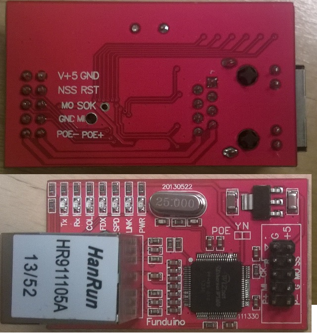
I have now tried on a breadboard with the same result "0;0;3;0;9;check wires". Swapped out the Pro Mini to a Nano same result. My conclusion would be that the Ethernet board I have can just not be used.

How I connected:
Ethernet board arduino pin
NSS/SS D10
MO/MO A0
MI/MI A1
SOK/CK A2
V+5 tried with 3.3v 5v and 9v
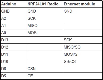
GND GNDThe radio was connected according to this
I'm still gona try the none SOFTSPI setup if I get the same result. edit -> same result here
-
@korttoma That W5100 module has no SPI_EN signal out on the pins, so you have to use soft SPI for it, or it will block the radio module. Or you can HW-patch the module to drive the inverse of the CS pin on the SPI_EN pin on the W5100 ASIC. If you instead does pull out SPI_EN to the Arduino you can use the config in the gateway sketch to handle the SPI_EN for you. I do this for my GW which has a W5100 module with SPI_EN available and it works a treat.
-
I tried to use the SOFT_SPI but I always get check wires. So it seems like there is also something else. Only time I managed to get the sketch running was with the none soft_spi setup and I had power disconnected from the Ethernet module during startup and connected it later.
-
@korttoma Sorry to be asking these probably stupid questions but have you checked that
- all wires are properly connected, and in-line with the config in the software
- the RF module is ok (tested multiple ones)
- supply voltage is relatively free of noise (I have seen noice up to 1V in relative amplitude without proper decoupling on my breadboard)
I am pretty sure you will never get the GW running on that module without either SOFT_SPI or a HW patch to it.
To me it sounds like a good start would be to get to the point where you can get it running on SOFT_SPI without the W5100 "present". Just to establish that you can communicate with the RF module.
If you can do it on HW SPI, then it should not be a problem with the RF module itself, more a config error for SOFT_SPI.
-
I we tried allot of different sources of power, this was the firs thing I did. I have a stupid question to. The radio connection are the same even if I use soft_spi right? Or should also the radio be connected to the 3 analog pins?
-
@korttoma No, the whole point of using SOFT_SPI is that you use different pins. The reason is that the W5100 "hogs" the SPI interface, so if you cannot access SPI_EN on W5100 then you cannot share SPI pins with W5100.
-
@hek Cool. maybe we can add a #define gateway and #define sensor to switch it between automagically.
W5100 gateway working 2+ days so far on 1.4.1 with this mod. THANKS
-
Found the problem. It was actualy this coment that made do the setup completely wrong:
@BulldogLowell said:
@niccodemi said:const uint8_t SOFT_SPI_MISO_PIN = 15; const uint8_t SOFT_SPI_MOSI_PIN = 14; const uint8_t SOFT_SPI_SCK_PIN = 16;and these are the correct pinouts for my Arduino Ethernet Shield, correct?
This is moving the SPI communication between the Uno and the shield off to another set of pins, and we are leaving the radio pins on hardware SPI?
So from this I had moved the Ethernet SPI pins to the allocated SOFT_SPI pins and not the radio pins like I was supposed to. @Dan-S did correct Jim but somehow I missed that part.
-
@korttoma said:
and these are the correct pinouts for my Arduino Ethernet Shield, correct?
No, this is the new pinout for the radio. Radio uses SoftSPI and the ethernet uses the good old hw SPI..
-
@hec that was what I was trying to explain with my post also. It was an earlier post by Jim that got me to do the setup incorrectly.
-
@Anticimex said:
@korttoma No, the whole point of using SOFT_SPI is that you use different pins. The reason is that the W5100 "hogs" the SPI interface, so if you cannot access SPI_EN on W5100 then you cannot share SPI pins with W5100.
Sorry for being confusing. The SOFT_SPI feature affects the RF module, not the W5100 module. Sorry for being unclear on that point.
But the reason for having SOFT_SPI is because of the W5100 modules violation of SPI praxis.
So; when using SOFT_SPI, RF module needs to be wired differently.
-
Just to make things a bit more clear for the next guy with a W5100 module that wants to use the SOFT_SPI :
download Master library 1.4.1
Patch file RF24_config.h (xxxx\MySensors\utility) to enable softspi,
uncomment (remove //) #define SOFTSPI
and change pin numbers as below:
const uint8_t SOFT_SPI_MISO_PIN = 15; const uint8_t SOFT_SPI_MOSI_PIN = 14; const uint8_t SOFT_SPI_SCK_PIN = 16;Connecto radio and Ethernet module according to this:

start arudino ide 1.5.8, open Ethernet Gateway sketch and amend/add below lines
add this line: #include <DigitalIO.h>
comment UIPEthernet.h (//#include <UIPEthernet.h>)
uncomment Ethernet.h (#include <Ethernet.h>)
and choose IP address
-
@korttoma Good overview. Actually, it is also possible to skip the IP address and use DHCP. Works just fine (though obviously you need a router that assignes a known IP to your chosen MAC, since the controller needs to know the IP of the GW.
-
I'm happy to see you have it working and nice job with the table, I think it caps off the whole thread.
It would be nice to see this setup as one of the detailed instructions on the main MySensors webpages.
@Anticimex, great to see the contribution!
-
Is it possible to use soft SPI for ethernet module and keep the original wiring for radio module?
-
@Mrlynx No. Ethernet library uses HW SPI.
-
@Anticimex said:
it is also possible to skip the IP address and use DHCP
So what do I need to change in the sketch to use DHCP?
-
@korttoma You set up the ethernet lib with only MAC, no IP as argument.
-
@Anticimex Is there any advantage to using DHCP?
-
Wether you use DHCP reservation on your router, or set the IP in the sketch, you need a static IP. You are configuring that static IP in the MySensors configuration on your Vera (assuming you are using Vera).
-
There is an advantage in using DHCP.
- You do not have to recompile and reflash your GW if you for some reason need to change it.
- If you have an environment using DHCP, introducing a device that enforces a certain IP is very bad practice, and you should then make sure your DHCP server make sure to not assign any device the same IP. Consequently, since the controller needs to know the IP of the GW, when DHCP is used, the DHCP server needs to statically tie the IP in question to the MAC the GW uses. But I think that is a much more sane solution in a network.
-
OK. So if I use DHCP and tell my router to reserve a particular address for my Gateway, operationally I won't notice any difference from directly assigning it as it is currently set up. But if I use DHCP I will be able to see it listed under "attached devices" on my router which is an advantage. With the current assignment, the router doesn't "see" my gateway. So I think I will try the DHCP route as an experiment because I like the idea of the router centrally managing and recognizing all of the network clients.
-
I have now updated the ethernet sketch and instructions on www.mysensors.org to give a bit clearer instructions on how to use W5100 module and SoftSPI.
-
Converted my Ethernet gateway to a DHCP connection. Went without a hitch and is now listed in my Netgear's list of attached devices and operating normally. So far, so good.
-
@hek said:
I have now updated the ethernet sketch and instructions on www.mysensors.org to give a bit clearer instructions on how to use W5100 module and SoftSPI.
greate! But you forgot one thing

RF24_config.h
const uint8_t SOFT_SPI_MISO_PIN = 15; const uint8_t SOFT_SPI_MOSI_PIN = 14; const uint8_t SOFT_SPI_SCK_PIN = 16;
-
Not sure why you had to change the defines in the config file? Pleas explain.
If look at my table you'll see that A0-A2 differs a bit from yours.
-
@hek said:
Not sure why you had to change
I changed because @niccodemi instructed us to. Maybe this only needs to be done with some other hardware then the one I'm using. Maybe he can explain. (I hope I will remeber that my setup differs from the official instructions when the time comes to update to the next version down the road.)
@hek said:
look at my table
I checked it again and your right it seems to be correct according to the config file, my bad.
-
my bad
 No problem. If @niccodemi had some good reason I'll update config and docs.
-
@hek please check below post; where should pins be changed if not in config file?
http://forum.mysensors.org/topic/466/ethernet-gateway-problem/24
-
Ahh.. then we should be fine with the defaults. @Anticimex did his own modification in config to fit his gateway.
-
@hek Yes, basically, when using SOFT_SPI, you need to decide what pins to use and set the config accordingly. I believe things has been standardized a bit since I meddled with that, because I abandoned the SOFT_SPI approach as soon as I managed to manipulate SPI_EN. Saves me both wires, program space and energy

-
I have problems with this setup. No matter what I try i get this printout from the Humidity sensor node:
req node id
send: 255-255-0-0 s=255,c=3,t=3,pt=0,l=0,st=ok:
sensor started, id 255
req node id
send: 255-255-0-0 s=255,c=3,t=3,pt=0,l=0,st=ok:
T: 20.70
req node id
send: 255-255-0-0 s=255,c=3,t=3,pt=0,l=0,st=ok:
H: 31.70Appreciate any tips and help!
-
I just switched to the ethernet gateway to try out native Domoticz support and quickly experienced the SPI issue that everyone has been talking about. Can someone explain how the MQTT gateway was able to run for several months with no issues, but the moment I flash the ETHERNET gateway on the same hardware everything goes belly up after a few hours?
-
@korttoma Can you post the link to the updated code and the instruction of using NRF with ethernet module.
-
@mainali said:
Can you post the link to the updated code and the instruction of using NRF with ethernet module.
I think everything you need to know is described here -> http://www.mysensors.org/build/ethernet_gateway
-
This post is deleted!
-
This post is deleted!