💬 NModule
-
NModule works with 3.3V power from header/programmer, and with a coin cell on the "power" board attached to it (tested with CR2025 and 220µF electrolytic capacitor).
I'll continue the tests tomorrow.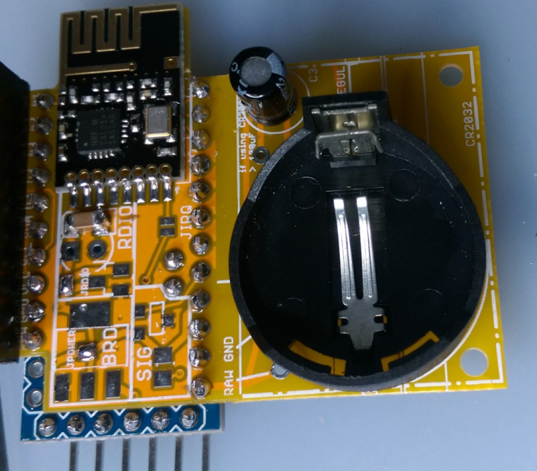
-
Not a big deal, but the silkscreen printing is jumbled together, making it hard to read:
Not sure if you're seeing it on your boards that way or not, but that's how OSH PARK did it.
-
Also, there are a number of "Pro Mini" type boards on the marketplace, and not all of them are 100% pin compatible. Which did you choose as your model? Is it the Sparkfun Pro Mini (which, if I'm not mistaken, was the first and the root of it all)? You may want to show a photo of the pro mini you're assuming along with a caption reading "your pro mini should look like this" just to avoid confusion.
-
I think you're the first to ever have a board made by myself in your hands. Congratulations :D
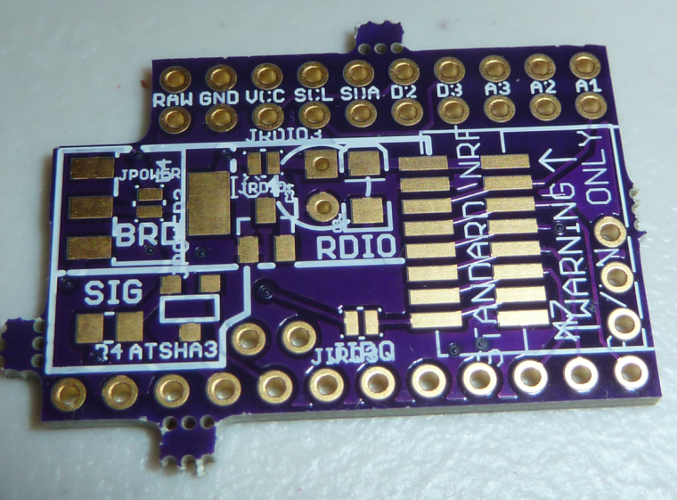
For the PCB it's probably due to a mistake from me when modifying the board to make the "core" Gerber version or when exporting files. I will have a look and fix asap.
For the ProMini I mainly use "The Simple" version from AliExpress, but my local seller has some "Sparkfun" branded clones and they are fine too.
You should only solder the connectors on the long sides and A4+A5. If it's not clear enough when reading assembly process please tell me.
Both types of ProMinis have the same layout for side pins and A4/A5, only the programming header and A6/A7 pins are different so it has no importance for NModule. -
I have used Seeed PCB service a few times in the past. They are not quite the cheapest but still excellent value, and for that little bit extra they do a better job than most.
-
Wow. $4.90 sounds great. What's their total turnaround time, including delivery? Actual delivery time, not just advertised delivery time, I mean.
-
Wow. $4.90 sounds great. What's their total turnaround time, including delivery? Actual delivery time, not just advertised delivery time, I mean.
-
for best battery life it is advisable to burn bootloader mentioned in the text.
How much would a battery lifetime be, for example one single temp sensor reading every 5min?
When using custom bootloader, then over the air updates cannot be used? Or could the MYSBootloader be configured to take most of the cr2025 battery? -
for best battery life it is advisable to burn bootloader mentioned in the text.
How much would a battery lifetime be, for example one single temp sensor reading every 5min?
When using custom bootloader, then over the air updates cannot be used? Or could the MYSBootloader be configured to take most of the cr2025 battery?Hello @dakipro,
what is necessary is to remove the default BOD limit, it is set at 2.7V and that is too high :
- even if CRxxxx cells were running like alkaline cells, this would waste a big share of the capacity, around 30% I think
- CRxxxx are not like alkaline cells, they have a high internal resistance and can supply only a limited amount of current, else the voltage drops. Meaning that in fact you will reach this 2.7V much faster if you have several RX/TX in a row
That is the main limit. I also advise to change the frequency to 1MHz and use internal oscillator if you have no calculation to do: door sensor, all basic I2C sensors etc etc because at 1MHz the power consumption is significantly lower. With NRF24 and I2C sensors it will not slow the "on" time much, data sent to/from radio and sensors takes very little time to transfer and main time is for waiting for radio reply or data from sensor: not affected by frequency so better have consumption as little as possible.
For battery lifetime if you remove leds and regulators with si7021 it will be way over 1 year. I have not tested those sensors for long enough, but I've had some round "puck" sensors with si7021 running for a few months on chinese CR2032 and I have not seen any voltage drop. Interval time is set to 1mn, it's not sending 5x more than 5mn interval (because often in one minute temp/hum don't change) but probably 2-3 times more, and with that I have no doubt the batteries will last way over a year.
My entrance door sensors is my oldest sensor, also running on pro mini (and still have it's TX led) and chinese CR2032, it uses the normally opened + normally closed reed swich and after 14-15 months of use is still at 85% of battery.
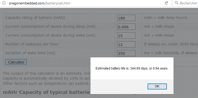
You can check that on battery life calculators anyway :
- with WDT disabled (= when you are not waking up periodically) consumption of board is below 2uA
- with WDT enabled and si7021 I measured it below 6uA
- when on with radio enabled for transmit/receive, at 1MHz power consumption is around 15mA when battery is new, a bit lower
This is a worse case scenario with battery capacity lowered to account for chinese battery (brand name is 220), and long wake up time with radio considered always on, sending data every 5 mns.
In reality radio is switched on only when data must be sent so time for reading voltage and sensor value is done consuming around 1mA at 1MHz.
-
thanks for detailed explanation, I was always a bit skeptical towards those small batteries, but your module (and documentation) clears all doubts :)
Do you have any experience with OTA updates? I understand that it also needs custom boot-loader (sorry still not having enough understanding about all the things that are involved in making one node, a lot of new terms for me :) ) -
thanks for detailed explanation, I was always a bit skeptical towards those small batteries, but your module (and documentation) clears all doubts :)
Do you have any experience with OTA updates? I understand that it also needs custom boot-loader (sorry still not having enough understanding about all the things that are involved in making one node, a lot of new terms for me :) )@dakipro no sorry I'm not (yet) using OTA.
But yes you need a specific bootloader that will download the new code from the controller and update flash memory of the atmega. There are 2 solutions for this (sorry forgot the names of bootloaders but check the documentation):- a bootloader that needs an external flash chip to store the downloaded code. It's a constraint, but it allows the sensor to continue running during download and it will be "offline" only for a short time during memory copy & reboot
- a bootloader that will copy directly the new code to the flash memory. It means as soon as the sketch started to download your node is offline until all the sketch is downloaded. And if update fails, your old sketch is still gone
OTA also need some specific code to check for the updates.
-
Thanks :)
Then I guess all that is left is to motivate you to start OTA and improve it (finetune) it to nmodule :)
I used it for regular modules and it is really practical, but I never had much luck with optimizing modules for battery performance. I would get a half year/year with 2 AA batteries, which is not that good comparing with your tweaks for CR battery.Keep us updated on other modules, people are waiting for your tests to start ordering :)
@dakipro for OTA I don't think there's much to do with batteries & OTA' Either the batteries allow continuous load (CR123, AAA, li-ion etc) or you just can't do it.
For battery life it's pretty simple but people keep choosing the wrong options and end up with poor battery life/instability etc etc. That's the reason I created the NModule: cheap and sure way to get a good battery life. Then I got a bit wild with the "shields" but that's another story :D
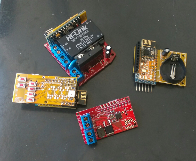
For other shields I'm making (slow) progress but I hope to take NModule, TH, Light/SSR, dual touch button, MiLight bridge and PWM boards out of the "work in progress" status during the next 2 weeks.
-
Hey @Nca78 I received the boards and components (yay!)
But... I connected three modules, and none of them works :(
They all have transport (radio?) fail like32 TSM:INIT
49 TSF:WUR:MS=0
81 !TSM:INIT:TSP FAIL
98 TSM:FAIL:CNT=1
114 TSM:FAIL:PDTI tried connecting radios from two different batches, I tried connecting only the radio and arduino, I tried powering it from separate powersupply and only debug via serial. I tried provided sketch and also tried dummy sketch from the examples. I tried using the CR battery, node works fine except that the radio doesn't start communicating.
I do measure 3V on the radio pins. I tried with and without radio cap.I am using chinese silicon mat to solder components on, I read somewhere that you use something similar *(not that I am spying on you :) ) but could it be that I am frying all the radios with static electricity?
I have used the mat before and it works fine with regular radios, nothing fried so far, but there is something preventing nodes from working :(Do you have any suggestions on how I can debug them and see what seems to be the problem?
Hello, @dakipro, can you show a picture of one of the board ?
Did you short the jumpers (JPOWER and JRDIO) if you're not using any regulators ?Yes I use a cheap silicon mat because it's so convenient, and I never had any problems with it all my radio worked.
-
Hey @Nca78 I received the boards and components (yay!)
But... I connected three modules, and none of them works :(
They all have transport (radio?) fail like32 TSM:INIT
49 TSF:WUR:MS=0
81 !TSM:INIT:TSP FAIL
98 TSM:FAIL:CNT=1
114 TSM:FAIL:PDTI tried connecting radios from two different batches, I tried connecting only the radio and arduino, I tried powering it from separate powersupply and only debug via serial. I tried provided sketch and also tried dummy sketch from the examples. I tried using the CR battery, node works fine except that the radio doesn't start communicating.
I do measure 3V on the radio pins. I tried with and without radio cap.I am using chinese silicon mat to solder components on, I read somewhere that you use something similar *(not that I am spying on you :) ) but could it be that I am frying all the radios with static electricity?
I have used the mat before and it works fine with regular radios, nothing fried so far, but there is something preventing nodes from working :(Do you have any suggestions on how I can debug them and see what seems to be the problem?
-
-
Looks as though the PA/LNA part of the silkscreen warning got largely obliterated by the solder pads.
Hello! It looks like you're interested in this conversation, but you don't have an account yet.
Getting fed up of having to scroll through the same posts each visit? When you register for an account, you'll always come back to exactly where you were before, and choose to be notified of new replies (either via email, or push notification). You'll also be able to save bookmarks and upvote posts to show your appreciation to other community members.
With your input, this post could be even better 💗
Register Login