nRF5 action!
-
@toyman I guess I made an error then. Thanks for pointing that out. In general, I haven't gotten much feedback on the PCB's that I've posted, so any feedback is always appreciated. :)
-
@omemanti said in nRF5 Bluetooth action!:
@neverdie Question is, did the DC/DC still work without the cap?
I believe it did. If you look at: https://www.openhardware.io/view/471/Ebyte-nRF52832-Small-Breakout-Board
which has the inductors soldered on, I believe that is the one that I tested. Enough time has passed though that I can't be 100% sure now. I made a number of different variations, and I didn't post all of them. -
@omemanti said in nRF5 Bluetooth action!:
@neverdie Question is, did the DC/DC still work without the cap?
I believe it did. If you look at: https://www.openhardware.io/view/471/Ebyte-nRF52832-Small-Breakout-Board
which has the inductors soldered on, I believe that is the one that I tested. Enough time has passed though that I can't be 100% sure now. I made a number of different variations, and I didn't post all of them.@neverdie said in nRF5 Bluetooth action!:
nough time has passed though that I can't be 100% sure now. I made a number of different variations, and I didn't post all of them
I used your schematic for a PCB I ordered yesterday :), did saw the post about the cap until it was too late :(
part of the game!Edit: according to your post https://forum.mysensors.org/topic/6961/nrf5-bluetooth-action/797 it did work
-
@korttoma have you tried the code @NeverDie put together using the LPCOMP ? With a QFAAH0 (which I believe is the same version than QFABC0, but with 256K flash) he went down to something like 4µA.
From the document you link, anomaly 70, it will be necessary to add an extra wait of 36us after that line, it's strange that @NeverDie never had any problem with it. Or maybe I misunderstand the document :)void activateLpComp() { ... while (!(NRF_LPCOMP->EVENTS_READY)) {} //wait until ready ... }Test code from @NeverDie using LPCOMP is here:
https://forum.mysensors.org/topic/6961/nrf5-bluetooth-action/1307I will try it on my board (using a module with QFAAH0) tomorrow, if power consumption is as low as expected I'll try on the beacon board.
[Edit] Just checked quickly my "beacon" board and it's using a QFAAH1 chip (made in 2017), so the test might not be relevant...
@nca78 said in nRF5 Bluetooth action!:
I will try it on my board (using a module with QFAAH0) tomorrow, if power consumption is as low as expected I'll try on the beacon board.
@NeverDie I have tried the sketch nearly unchanged (only changed to lines because I use pin P0.01 so AIN2) and my current consumption is a bit over 30uA, do you have any idea of what I should check ? (I tried with both versions 0.1 and 0.3 of MySensors NRF5 boards).
At the moment my board only has a led and a DRV5032FB (<<1uA) in addition to the nrf51 module. -
Just to close the loop on DC-DC:
Figure 2
-
@nca78 said in nRF5 Bluetooth action!:
I will try it on my board (using a module with QFAAH0) tomorrow, if power consumption is as low as expected I'll try on the beacon board.
@NeverDie I have tried the sketch nearly unchanged (only changed to lines because I use pin P0.01 so AIN2) and my current consumption is a bit over 30uA, do you have any idea of what I should check ? (I tried with both versions 0.1 and 0.3 of MySensors NRF5 boards).
At the moment my board only has a led and a DRV5032FB (<<1uA) in addition to the nrf51 module.@nca78 said in nRF5 Bluetooth action!:
do you have any idea of what I should check ?
Have you tried disabling serial?
-
@nca78 said in nRF5 Bluetooth action!:
do you have any idea of what I should check ?
Have you tried disabling serial?
-
Unsure then.
-
@nca78 said in nRF5 Bluetooth action!:
I will try it on my board (using a module with QFAAH0) tomorrow, if power consumption is as low as expected I'll try on the beacon board.
@NeverDie I have tried the sketch nearly unchanged (only changed to lines because I use pin P0.01 so AIN2) and my current consumption is a bit over 30uA, do you have any idea of what I should check ? (I tried with both versions 0.1 and 0.3 of MySensors NRF5 boards).
At the moment my board only has a led and a DRV5032FB (<<1uA) in addition to the nrf51 module.@nca78 said in nRF5 Bluetooth action!:
@NeverDie I have tried the sketch nearly unchanged (only changed to lines because I use pin P0.01 so AIN2) and my current consumption is a bit over 30uA, do you have any idea of what I should check ? (I tried with both versions 0.1 and 0.3 of MySensors NRF5 boards).
At the moment my board only has a led and a DRV5032FB (<<1uA) in addition to the nrf51 module.Ok, case closed, it was just because the SWD pins were still connected to my NRF52 DK. When I just connect VCC and GND it's down to something a bit below 5uA. I'm using a multimeter and DK is at 2.8V so real consumption will be a bit higher. But it should give me a battery life around 1year for my bedroom doors, so I'll just use my nrf51 modules for that and move to the more interesting nrf52.
-
@nca78 said in nRF5 Bluetooth action!:
@NeverDie I have tried the sketch nearly unchanged (only changed to lines because I use pin P0.01 so AIN2) and my current consumption is a bit over 30uA, do you have any idea of what I should check ? (I tried with both versions 0.1 and 0.3 of MySensors NRF5 boards).
At the moment my board only has a led and a DRV5032FB (<<1uA) in addition to the nrf51 module.Ok, case closed, it was just because the SWD pins were still connected to my NRF52 DK. When I just connect VCC and GND it's down to something a bit below 5uA. I'm using a multimeter and DK is at 2.8V so real consumption will be a bit higher. But it should give me a battery life around 1year for my bedroom doors, so I'll just use my nrf51 modules for that and move to the more interesting nrf52.
@nca78 would you mind sharing your sketch files for your door sensors?
As I'm not a programmer and not so good at programing I usually rely on example code to get anything done. More examples gives me more understanding how things should be done.- Tomas
-
@nca78 would you mind sharing your sketch files for your door sensors?
As I'm not a programmer and not so good at programing I usually rely on example code to get anything done. More examples gives me more understanding how things should be done. -
@toyman I guess I made an error then. Thanks for pointing that out. In general, I haven't gotten much feedback on the PCB's that I've posted, so any feedback is always appreciated. :)
@neverdie said in nRF5 Bluetooth action!:
@toyman I guess I made an error then. Thanks for pointing that out.
I actually think you were correct in your design, @NeverDie ;-)
A while ago part of the e73-2g4m04s schematic was posted on this forum:
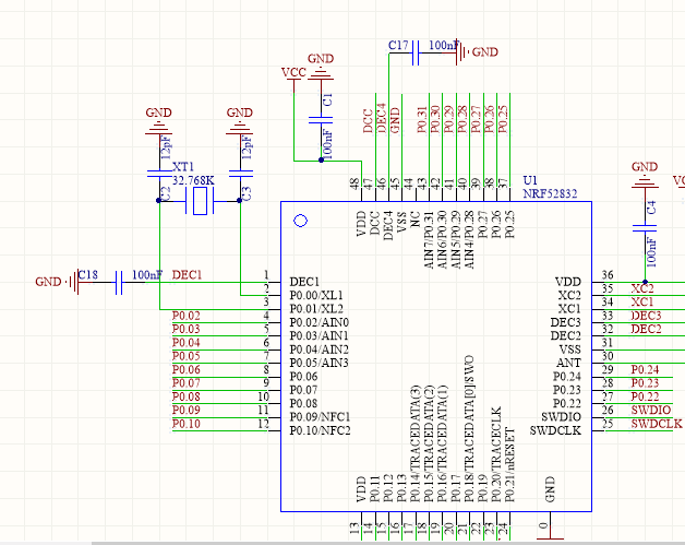
Clearly the inductors to use the DC/DC converter are not connected to DCC. There is however a capacitor C17 from DEC4 to GND.
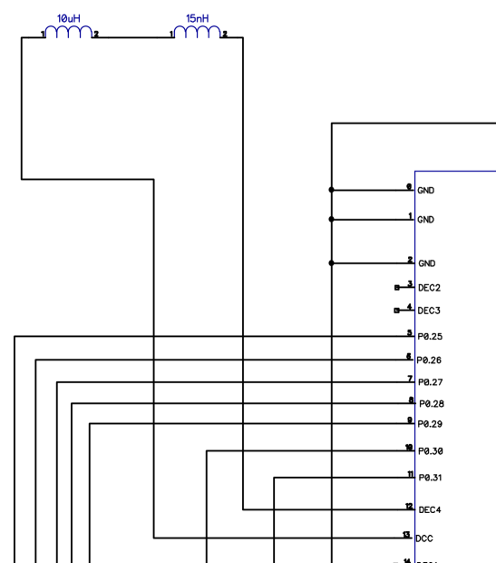
The Nordic reference schematic shows the missing L2 and L3, but capacitor C10 is actually present in the e73-2g4m04s (the mentioned C17, albeit only 100nF instead of 1.0uF in the reference):
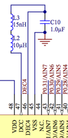
Therefore I think your breakout is correct, as only the inductors between DCC and DEC4 need to be added to match the reference schematic :+1:
http://yveaux.blogspot.nl
-
@neverdie said in nRF5 Bluetooth action!:
@toyman I guess I made an error then. Thanks for pointing that out.
I actually think you were correct in your design, @NeverDie ;-)
A while ago part of the e73-2g4m04s schematic was posted on this forum:
Clearly the inductors to use the DC/DC converter are not connected to DCC. There is however a capacitor C17 from DEC4 to GND.
The Nordic reference schematic shows the missing L2 and L3, but capacitor C10 is actually present in the e73-2g4m04s (the mentioned C17, albeit only 100nF instead of 1.0uF in the reference):
Therefore I think your breakout is correct, as only the inductors between DCC and DEC4 need to be added to match the reference schematic :+1:
-
@Mika what is your experience regarding battery consumption on these?
I put together a sketch witch seems to work fine but one CR2032 just lasts a couple of days.
Sketch:
/**
 * The MySensors Arduino library handles the wireless radio link and protocol
 * between your home built sensors/actuators and HA controller of choice.
 * The sensors forms a self healing radio network with optional repeaters. Each
 * repeater and gateway builds a routing tables in EEPROM which keeps track of the
 * network topology allowing messages to be routed to nodes.
 *
 * Created by Henrik Ekblad <henrik.ekblad@mysensors.org>
 * Copyright (C) 2013-2015 Sensnology AB
 * Full contributor list: https://github.com/mysensors/Arduino/graphs/contributors
 *
 * Documentation: http://www.mysensors.org
 * Support Forum: http://forum.mysensors.org
 *
 * This program is free software; you can redistribute it and/or
 * modify it under the terms of the GNU General Public License
 * version 2 as published by the Free Software Foundation.
 *
 *******************************
 */

// Enable debug prints to serial monitor
//#define MY_DEBUG

// Define a static node address, remove if you want auto address assignment
//#define MY_NODE_ID 26                                                          // Kök
#define MY_NODE_ID 27                                                          // Test device


// Enable and select radio type attached

#define MY_RADIO_NRF5_ESB

#include <MySensors.h>

#define SN "NRF5 Scene"
#define SV "1.0"

#define CHILD_ID_SCENE 1

// PIN for the buttons
byte buttonOne = 28;

//Bounce debouncer[NUMBUTTONS];
int buttonOneoldValue;


// Pin definitions
#define DIGITAL_INPUT_INT 28   // The digital input you attached your interrupt  (Only 2 and 3 generates interrupt!)


// Sensor messages
MyMessage msgOn(CHILD_ID_SCENE, V_SCENE_ON);

// Global settings
uint16_t SceneOne = 0;
uint16_t SceneTwo = 1;


void blinkityBlink(uint8_t repetitions) {
  for (int x=0;x<repetitions;x++) {
    digitalWrite(LED_BUILTIN,HIGH);
    wait(20);
    digitalWrite(LED_BUILTIN,LOW);
    wait(100);
    digitalWrite(LED_BUILTIN,HIGH);
    wait(20);
    digitalWrite(LED_BUILTIN,LOW);
    if (x<(repetitions-1)) {  //skip waiting at the end of the final repetition
      wait(500);
    }
  }
}


/****************************************************
 *
 * Setup code
 *
 ****************************************************/

void setup() {

  hwPinMode(LED_BUILTIN,OUTPUT_D0H1);
  blinkityBlink(2);  //signify power-up and start of operations

  NRF_CLOCK->INTENSET=B11;  //enable interrupts for EVENTS_HFCLKSTARTED and  EVENTS_LFCLKSTARTED
  NRF_CLOCK->TASKS_HFCLKSTART=1;  //start the high frequency crystal oscillator clock
  while (!(NRF_CLOCK->EVENTS_HFCLKSTARTED)) {} //wait until high frequency crystal oscillator clock is up to speed and working

  hwPinMode(DIGITAL_INPUT_INT, INPUT_PULLUP);

    /// Make input & enable pull-up resistors on switch pins
  hwPinMode(buttonOne, INPUT_PULLUP);
  buttonOneoldValue = -1;


  sendBattLevel();


}

void presentation()  {
  sendSketchInfo(SN, SV);
  //present the scene controller to gateway
  wait(10);
  present(CHILD_ID_SCENE, S_SCENE_CONTROLLER);

  wait(10);
}


/***********************************************
 *
 *  Main loop function
 *
 ***********************************************/
void loop() {

  // Check for button activity

  int value = digitalRead(buttonOne);

  if (value != buttonOneoldValue)
    {
      // Send in the new value
      if (value == LOW)
      {
        send(msgOn.set(SceneOne));

        wait(20);

        send(msgOn.set(SceneTwo));

        sendBattLevel();


      }
      buttonOneoldValue = value;
    }

  sleep(digitalPinToInterrupt(DIGITAL_INPUT_INT), CHANGE, 0);

}


/********************************************
 *
 * Sends battery information (battery percentage)
 *
 * Parameters
 * - force : Forces transmission of a value
 *
 *******************************************/
void sendBattLevel()
{
    long vcc = hwCPUVoltage();

    // Calculate percentage

    vcc = vcc - 1800; // subtract 1.9V from vcc, as this is the lowest voltage we will operate at

    long percent = vcc / 14.0;
    sendBatteryLevel(percent);

}
I noticed that the chip sais:
N51822
QFABC0
1646UUQFAB translates to 16kB RAM, 128kB flash and I can not even select this option in the arduino IDE. Can this be the problem?
@d00616 refer to his document for some high current consumption issue but I'm not sure what to do with the info.
Is there something wrong with my sketch or is there just an old crappy chip on the device??
@korttoma said in nRF5 Bluetooth action!:
@Mika what is your experience regarding battery consumption on these?
I put together a sketch witch seems to work fine but one CR2032 just lasts a couple of days.
I noticed that the chip sais:
N51822
QFABC0
1646UUQFAB translates to 16kB RAM, 128kB flash and I can not even select this option in the arduino IDE. Can this be the problem?
@d00616 refer to his document for some high current consumption issue but I'm not sure what to do with the info.
Is there something wrong with my sketch or is there just an old crappy chip on the device??
So I tried your code with a more recent version of the chip and I have a power consumption around 1mA.
This is not surprising because in fact issue 39 seems to not be completely fixed, if I believe this link:
https://devzone.nordicsemi.com/f/nordic-q-a/577/current-consumption-when-using-rtc-ppi-and-gpiote#post-id-18533"The third revision hardware of the nRF51 has a solution for the GPIOTE OUT tasks, which has very low current consumption (<1uA). The third revision nRF51 hardware will be released in a few days. The third revision hardware still does not have a solution for the GPIOTE IN events, they still consume high current, so for low current applications, use the GPIOTE PORT event instead or the app_button libary."
From what I see it was never fixed.
-
I'm seeing a special offer for this at 2€ with coupon https://www.aliexpress.com/item/nRF52832-2-4GHz-Wireless-rf-Module-CDSENET-E73-2G4M04S-SPI-SMD-rf-Receiver-transmitter-Bluetooth-Module/32819293925.html
Should i go ahead? -
I'm seeing a special offer for this at 2€ with coupon https://www.aliexpress.com/item/nRF52832-2-4GHz-Wireless-rf-Module-CDSENET-E73-2G4M04S-SPI-SMD-rf-Receiver-transmitter-Bluetooth-Module/32819293925.html
Should i go ahead? -
I don't know if it is a good one and I already have a bunch of stuff I bought still in the drawer :sweat_smile:
-
@korttoma said in nRF5 Bluetooth action!:
@Mika what is your experience regarding battery consumption on these?
I put together a sketch witch seems to work fine but one CR2032 just lasts a couple of days.
I noticed that the chip sais:
N51822
QFABC0
1646UUQFAB translates to 16kB RAM, 128kB flash and I can not even select this option in the arduino IDE. Can this be the problem?
@d00616 refer to his document for some high current consumption issue but I'm not sure what to do with the info.
Is there something wrong with my sketch or is there just an old crappy chip on the device??
So I tried your code with a more recent version of the chip and I have a power consumption around 1mA.
This is not surprising because in fact issue 39 seems to not be completely fixed, if I believe this link:
https://devzone.nordicsemi.com/f/nordic-q-a/577/current-consumption-when-using-rtc-ppi-and-gpiote#post-id-18533"The third revision hardware of the nRF51 has a solution for the GPIOTE OUT tasks, which has very low current consumption (<1uA). The third revision nRF51 hardware will be released in a few days. The third revision hardware still does not have a solution for the GPIOTE IN events, they still consume high current, so for low current applications, use the GPIOTE PORT event instead or the app_button libary."
From what I see it was never fixed.
@nca78 said in nRF5 Bluetooth action!:
use the GPIOTE PORT event instead or the app_button libary.
Thanks again for pointing out a possible solution but again I do not know how. I will just have to be patient and wait for someone to post an example of how to use one of the methods you mentioned.
-
I have started to test a NRF51822
and I can upload to it with Arduino IDE but I want to use vim + platformio. And I think i'm quite close :)
When I ran platformio upload --target upload
GNU MCU Eclipse 64-bits Open On-Chip Debugger 0.10.0+dev-00392-gbe9ef0b0 (2018-01-12-14:56)
Licensed under GNU GPL v2
For bug reports, read
http://openocd.org/doc/doxygen/bugs.html
0x4000
Info : The selected transport took over low-level target control. The results might differ compared to plain JTAG/SWD
adapter speed: 1000 kHz
Info : Unable to match requested speed 1000 kHz, using 950 kHz
Info : Unable to match requested speed 1000 kHz, using 950 kHz
Info : clock speed 950 kHz
Info : STLINK v2 JTAG v17 API v2 SWIM v4 VID 0x0483 PID 0x3748
Info : using stlink api v2
Info : Target voltage: 3.225841
Info : nrf51.cpu: hardware has 4 breakpoints, 2 watchpoints
Info : Listening on port 3333 for gdb connections
target halted due to debug-request, current mode: Thread
xPSR: 0xc1000000 pc: 0x000021a4 msp: 0x20004000
** Programming Started **
auto erase enabled
Warn : Unknown device (HWID 0x000000d1)
Warn : using fast async flash loader. This is currently supported
Warn : only with ST-Link and CMSIS-DAP. If you have issues, add
Warn : "set WORKAREASIZE 0" before sourcing nrf51.cfg/nrf52.cfg to disable it
target halted due to breakpoint, current mode: Thread
xPSR: 0x61000000 pc: 0x2000001e msp: 0x20004000
wrote 33792 bytes from file .pioenvs/nrf51_dk/firmware.hex in 1.594509s (20.696 KiB/s)
** Programming Finished **
** Verify Started **
target halted due to breakpoint, current mode: Thread
xPSR: 0x61000000 pc: 0x2000002e msp: 0x20004000
verified 32960 bytes in 0.236646s (136.015 KiB/s)
** Verified OK **
** Resetting Target **
shutdown command invoked
and the output in Arduino IDE looks like:
Open On-Chip Debugger 0.10.0-dev-00254-g696fc0a (2016-04-09-12:07)
Licensed under GNU GPL v2
For bug reports, read
	http://openocd.org/doc/doxygen/bugs.html
debug_level: 0
0x4000
adapter speed: 1000 kHz
nrf51.cpu: target state: halted
target halted due to debug-request, current mode: Thread
xPSR: 0xc1000000 pc: 0x0000251c msp: 0x20004000
** Programming Started **
auto erase enabled
nrf51.cpu: target state: halted
target halted due to breakpoint, current mode: Thread
xPSR: 0x61000000 pc: 0x2000001e msp: 0x20004000
wrote 31744 bytes from file /tmp/arduino_build_390477/Si7021_TemperatureNode_v007_voltage__version_7_board_.ino.hex in 1.500105s (20.665 KiB/s)
** Programming Finished **
** Verify Started **
nrf51.cpu: target state: halted
target halted due to breakpoint, current mode: Thread
xPSR: 0x61000000 pc: 0x2000002e msp: 0x20004000
verified 31580 bytes in 0.234860s (131.312 KiB/s)
** Verified OK **
** Resetting Target **
shutdown command invoked
and my platfromio.ini looks like:
[env:nrf51_dk]
platform = nordicnrf51
framework = arduino
board = nrf51_dk
upload_protocol = stlink
Should I modify the nrf51_dk.cfg or can anyone see whats the problem is?