Skip to content
  • OpenHardware.io
  • Categories
  • Recent
  • Tags
  • Popular
Skins
  • Light
  • Brite
  • Cerulean
  • Cosmo
  • Flatly
  • Journal
  • Litera
  • Lumen
  • Lux
  • Materia
  • Minty
  • Morph
  • Pulse
  • Sandstone
  • Simplex
  • Sketchy
  • Spacelab
  • United
  • Yeti
  • Zephyr
  • Dark
  • Cyborg
  • Darkly
  • Quartz
  • Slate
  • Solar
  • Superhero
  • Vapor

  • Default (No Skin)
  • No Skin
Collapse
Brand Logo
  1. Home
  2. My Project
  3. nRF5 action!
  • Getting Started
  • Controller
  • Build
  • Hardware
  • Download/API
  • Forum
  • Store

nRF5 action!

Scheduled Pinned Locked Moved My Project
1.9k Posts 49 Posters 630.8k Views 44 Watching
  • Oldest to Newest
  • Newest to Oldest
  • Most Votes
Reply
  • Reply as topic
Log in to reply
This topic has been deleted. Only users with topic management privileges can see it.
  • gohanG gohan

    Is this one ok? https://www.ebay.it/itm/ST-Link-V2-Programming-Unit-mini-STM8-STM32-Emulator-Downloader-M89/122178354704?hash=item1c7265be10:g:xx4AAOSwm7pZ2Kb-

    NRF52832-DK is kind of way over budget :D

    O Offline
    O Offline
    Omemanti
    wrote on last edited by
    #1501

    @gohan sure, I bought some of those. Works great. One crashed so now I bought a couple, just to be sure.. :)

    YveauxY 1 Reply Last reply
    1
    • Nca78N Nca78

      @korttoma said in nRF5 Bluetooth action!:

      @Mika what is your experience regarding battery consumption on these?

      LINK

      I put together a sketch witch seems to work fine but one CR2032 just lasts a couple of days.
      I noticed that the chip sais:
      N51822
      QFABC0
      1646UU

      QFAB translates to 16kB RAM, 128kB flash and I can not even select this option in the arduino IDE. Can this be the problem?

      @d00616 refer to his document for some high current consumption issue but I'm not sure what to do with the info.

      Is there something wrong with my sketch or is there just an old crappy chip on the device??

      So I tried your code with a more recent version of the chip and I have a power consumption around 1mA.
      This is not surprising because in fact issue 39 seems to not be completely fixed, if I believe this link:
      https://devzone.nordicsemi.com/f/nordic-q-a/577/current-consumption-when-using-rtc-ppi-and-gpiote#post-id-18533

      "The third revision hardware of the nRF51 has a solution for the GPIOTE OUT tasks, which has very low current consumption (<1uA). The third revision nRF51 hardware will be released in a few days. The third revision hardware still does not have a solution for the GPIOTE IN events, they still consume high current, so for low current applications, use the GPIOTE PORT event instead or the app_button libary."

      From what I see it was never fixed.

      Nca78N Offline
      Nca78N Offline
      Nca78
      Hardware Contributor
      wrote on last edited by
      #1502

      @nca78 said in nRF5 Bluetooth action!:

      So I tried your code with a more recent version of the chip and I have a power consumption around 1mA.
      This is not surprising because in fact issue 39 seems to not be completely fixed, if I believe this link:
      https://devzone.nordicsemi.com/f/nordic-q-a/577/current-consumption-when-using-rtc-ppi-and-gpiote#post-id-18533

      "The third revision hardware of the nRF51 has a solution for the GPIOTE OUT tasks, which has very low current consumption (<1uA). The third revision nRF51 hardware will be released in a few days. The third revision hardware still does not have a solution for the GPIOTE IN events, they still consume high current, so for low current applications, use the GPIOTE PORT event instead or the app_button libary."

      From what I see it was never fixed.

      Took time but after failure trying to make a version by myself I decided to include app_gpiote library from SDK in my script and it works, it's using around 1uA more than LPCOMP (I measure 5.5 uA with my multimeter) but it can use any pin and in theory any number of pins without increasing power consumption.
      The behavior is similar to pin change interrupt on ATMega328, you have one interrupt for all the pins you are watching, so you have to check which pin generated the interrupt but app_gpiote is preparing the work for you.
      I have this consumption with a similar script than @Neverdie for LPCOMP: using MySensors with MY_CORE_ONLY, preparing the interrupt then calling the sleep(ms) function from MySensors library, and it works as expected changing status of led immediately when I change status of pin, and waking up at the end of the interval if I don't.
      I'll do more tests tomorrow including a full MySensors script, and post the info here. It needs a bunch of files from SDK and adding a (weak) attribute to GPIOTE_IRQHandler() in sandeepmistry's code so it can be overridden in the script.

      1 Reply Last reply
      2
      • O Omemanti

        @gohan sure, I bought some of those. Works great. One crashed so now I bought a couple, just to be sure.. :)

        YveauxY Offline
        YveauxY Offline
        Yveaux
        Mod
        wrote on last edited by
        #1503

        @omemanti said in nRF5 Bluetooth action!:

        I bought some of those. Works great

        Do you use them with windows?
        I tried to get them to program an nrf52832, but openocd in Arduino ide under windows doesn't detect them...
        Both stlinks work in Linux.

        http://yveaux.blogspot.nl

        mfalkviddM O 2 Replies Last reply
        0
        • YveauxY Yveaux

          @omemanti said in nRF5 Bluetooth action!:

          I bought some of those. Works great

          Do you use them with windows?
          I tried to get them to program an nrf52832, but openocd in Arduino ide under windows doesn't detect them...
          Both stlinks work in Linux.

          mfalkviddM Offline
          mfalkviddM Offline
          mfalkvidd
          Mod
          wrote on last edited by
          #1504

          @yveaux I have used a ST-Link v2 (clone) on Windows 7, didn't run into any problems.

          YveauxY 1 Reply Last reply
          0
          • mfalkviddM mfalkvidd

            @yveaux I have used a ST-Link v2 (clone) on Windows 7, didn't run into any problems.

            YveauxY Offline
            YveauxY Offline
            Yveaux
            Mod
            wrote on last edited by
            #1505

            @mfalkvidd from the arduino ide? Did you follow any guide or remember specific settings?

            http://yveaux.blogspot.nl

            mfalkviddM 1 Reply Last reply
            0
            • YveauxY Yveaux

              @mfalkvidd from the arduino ide? Did you follow any guide or remember specific settings?

              mfalkviddM Offline
              mfalkviddM Offline
              mfalkvidd
              Mod
              wrote on last edited by
              #1506

              @yveaux yes from the Arduino IDE. I just followed this guide.

              1 Reply Last reply
              0
              • mfalkviddM Offline
                mfalkviddM Offline
                mfalkvidd
                Mod
                wrote on last edited by
                #1507

                I did follow https://github.com/sandeepmistry/arduino-BLEPeripheral as well (for a non-MySensors use case). Not sure which one I did first.

                YveauxY 1 Reply Last reply
                0
                • mfalkviddM mfalkvidd

                  I did follow https://github.com/sandeepmistry/arduino-BLEPeripheral as well (for a non-MySensors use case). Not sure which one I did first.

                  YveauxY Offline
                  YveauxY Offline
                  Yveaux
                  Mod
                  wrote on last edited by Yveaux
                  #1508

                  @mfalkvidd hmmm... No specific mention of any st-link stuff to configure. Must be me then :scream:
                  I just wanted to try some ST-links I ordered.
                  Ah well, I'll give it another try and otherwise go back to my j-link, which works flawlessly.

                  Thanks anyway!

                  http://yveaux.blogspot.nl

                  1 Reply Last reply
                  0
                  • YveauxY Yveaux

                    @omemanti said in nRF5 Bluetooth action!:

                    I bought some of those. Works great

                    Do you use them with windows?
                    I tried to get them to program an nrf52832, but openocd in Arduino ide under windows doesn't detect them...
                    Both stlinks work in Linux.

                    O Offline
                    O Offline
                    Omemanti
                    wrote on last edited by Omemanti
                    #1509

                    @yveaux jup, both work on Windows . I had to install the right drivers using zadig.

                    I only use the Arduino IDE for uploading, just select the st-link and it works.

                    YveauxY 2 Replies Last reply
                    0
                    • O Omemanti

                      @yveaux jup, both work on Windows . I had to install the right drivers using zadig.

                      I only use the Arduino IDE for uploading, just select the st-link and it works.

                      YveauxY Offline
                      YveauxY Offline
                      Yveaux
                      Mod
                      wrote on last edited by
                      #1510

                      @omemanti ok, thanks for the feedback. I'll give that a try then :+1:

                      http://yveaux.blogspot.nl

                      1 Reply Last reply
                      0
                      • O Omemanti

                        @yveaux jup, both work on Windows . I had to install the right drivers using zadig.

                        I only use the Arduino IDE for uploading, just select the st-link and it works.

                        YveauxY Offline
                        YveauxY Offline
                        Yveaux
                        Mod
                        wrote on last edited by
                        #1511

                        @omemanti yup, installed WinUSB driver with Zadig and worked instantly! Thanks again!

                        http://yveaux.blogspot.nl

                        mfalkviddM 1 Reply Last reply
                        2
                        • YveauxY Yveaux

                          @omemanti yup, installed WinUSB driver with Zadig and worked instantly! Thanks again!

                          mfalkviddM Offline
                          mfalkviddM Offline
                          mfalkvidd
                          Mod
                          wrote on last edited by
                          #1512

                          @yveaux I have messed with some SDR dongles and might have installed WinUSB with Zadig earlier to get the SDR to work.

                          YveauxY 1 Reply Last reply
                          0
                          • mfalkviddM mfalkvidd

                            @yveaux I have messed with some SDR dongles and might have installed WinUSB with Zadig earlier to get the SDR to work.

                            YveauxY Offline
                            YveauxY Offline
                            Yveaux
                            Mod
                            wrote on last edited by
                            #1513

                            @mfalkvidd yeah, now you tell me :kissing_heart:

                            http://yveaux.blogspot.nl

                            1 Reply Last reply
                            0
                            • Nca78N Offline
                              Nca78N Offline
                              Nca78
                              Hardware Contributor
                              wrote on last edited by
                              #1514

                              So I made a version of script with MySensors library, it's not a final version and needs some cleaning and improvements but it seems to work well (I didn't test so much yet :)) and shows basic usage. Comments should be enough to understand what to change to adapt to your board. Current script is for my board:

                              • BUTTON_1 on pin 1, it's a hall sensor for door so no pullup and sensing on up=>down and down=>up changes
                              • BUTTON_2 on pin 3, push button with pullup and debouncing, sensing only on up=>down when button is pressed. At the moment it just makes some light blinking to show it's detected.
                              • led on pin 2.

                              I join the main script file and the MyBoardNRF5 files, for using with MyBoardNRF5 nrf51822. Files to include are described in the main script file, but don't forget to add a weak attribute in the WInterrupt.c file before the GPIOTE_IRQHandler so it can be overridden.

                              __attribute__ ((weak))
                              void GPIOTE_IRQHandler()
                              

                              On my Windows PC this file is in C:\Users[your user name]\AppData\Local\Arduino15\packages\sandeepmistry\hardware\nRF5\0.5.1\cores\nRF5

                              Main script file:

                              // Include app_gpiote and related files from NRF5 SDK 12
                              extern "C" {
                              #include "app_gpiote.h"
                              #include "nrf_gpio.h"
                              #include "app_error.h"
                              }
                              
                              // Files to include from SDK:
                              // app_error_weak.h + .c
                              // app_gpiote.h + .c
                              // app_util.h
                              // nordic_common.h
                              // nrf_error.h
                              // nrf_gpio.h
                              // sdk_errors.h
                              // app_error.h + .c
                              //   for this last one (c file) I decided to stop the endless list of includes so I commented the following includes:
                              //   #include "sdk_errors.h", #include "nrf_log.h", #include "nrf_log_ctrl.h"  lines
                              
                              #include <nrf.h>
                              
                              #define IS_NRF51  //true if the target is an nRF51.  If an nRF52, then comment this line out!
                              #define APP_GPIOTE_MAX_USERS 1  // max users for app_gpiote, we only use one
                              #define MY_RADIO_NRF5_ESB
                              #define MY_NODE_ID 60   // To avoid getting a new ID at each flashing of the sensors...
                              
                              #include <MySensors.h>
                              
                              
                              // variables for app_gpiote calls
                              uint32_t err_code;
                              static app_gpiote_user_id_t m_gpiote_user_id;
                              uint32_t PIN_BUTTON1_MASK; // Mask for PIN_BUTTON1 input
                              uint32_t PIN_BUTTON2_MASK; // Mask for PIN_BUTTON2 input
                              
                              // defines variables for MySensors
                              #define SN "22Board Door Basic"
                              #define SV "0.2"
                              // Sensor messages
                              #define CHILD_ID_DOOR 1
                              MyMessage doorMsg(CHILD_ID_DOOR, V_TRIPPED);
                              bool last_sent_value;
                              bool door_status;
                              long last_button2_event = 0;
                              
                              // Cause of interrupt
                              volatile byte interrupt_cause = 0;
                              
                              
                              // Settings to avoid killing coin cell in case of connection problem
                              #define MY_TRANSPORT_WAIT_READY_MS  10000
                              #define MY_SLEEP_TRANSPORT_RECONNECT_TIMEOUT_MS 5000
                              
                              // Battery settings
                              #define BATTERY_ALERT_LEVEL 30  // (%) Will triple blink after sending data if battery is equal or below this level
                              // Parameters for VCC measurement
                              #define BATTERY_VCC_MIN  2400  // Minimum expected Vcc level, in milliVolts. 
                              #define BATTERY_VCC_MAX  2900  // Maximum expected Vcc level, in milliVolts.
                              // This a a coefficient to fix the imprecision of measurement of the battery voltage
                              #define BATTERY_COEF 1000.0f  // (reported voltage / voltage) * 1000
                              uint16_t currentBatteryPercent;
                              uint16_t lastBatteryPercent = -1;
                              // Enables/disables sleeps between sendings to optimize for CR2032 or similar coin cell
                              #define USE_COIN_CELL
                              
                              
                              // Called before initialization of the library
                              void before() {
                                hwPinMode(LED_BUILTIN, OUTPUT_D0H1);
                                blinkityBlink(2, 3);
                              }
                              
                              // Setup node
                              void setup(void) {
                              
                                //Configure button pins as inputs
                                nrf_gpio_cfg_input(PIN_BUTTON1, NRF_GPIO_PIN_NOPULL);
                                nrf_gpio_cfg_input(PIN_BUTTON2, NRF_GPIO_PIN_PULLUP);
                                APP_GPIOTE_INIT(APP_GPIOTE_MAX_USERS);               //Only initialize once. Increase value of APP_GPIOTE_MAX_USERS if needed
                              
                                // Initialize value of pin (for DRV5032 hall sensor HIGH = no magnet nearby = door opened);
                                door_status = digitalRead(PIN_BUTTON1);
                                last_sent_value = !door_status; // so we always send value in first loop
                              
                                // Registers user and pins we are "watching"
                                //   gpiote_event_handler is handler called by interrupt, see method below
                                PIN_BUTTON1_MASK = 1 << PIN_BUTTON1; // Set mask, will be used for registration and interrupt handler
                                PIN_BUTTON2_MASK = 1 << PIN_BUTTON2; // Set mask, will be used for registration and interrupt handler
                                //  app_gpiote_user_register(p_user_id, pins_low_to_high_mask, pins_high_to_low_mask, event_handler)
                                //  to have no trigger for high=>low or low=>high change on your button, pass 0 instead
                                //  here I check PIN_BUTTON1 on both low=>high and high=>low changes and PIN_BUTTON2 only on high=>low change when someone presses the button
                                err_code = app_gpiote_user_register(&m_gpiote_user_id, PIN_BUTTON1_MASK, PIN_BUTTON1_MASK | PIN_BUTTON2_MASK, gpiote_event_handler);
                                APP_ERROR_CHECK(err_code);  // will reset if user registration fails
                              
                                // Enable SENSE and interrupt
                                err_code = app_gpiote_user_enable(m_gpiote_user_id);
                                APP_ERROR_CHECK(err_code);  // will reset if SENSE enabling fails
                              
                                // initialize last event for button2 debounce
                                last_button2_event = millis();
                              }
                              
                              void presentation()  {
                                sendSketchInfo(SN, SV);
                                present(CHILD_ID_DOOR, S_DOOR);
                              }
                              
                              // Sleep between sendings to preserve coin cell
                              //  if not using button cell just make sure the #define USE_COIN_CELL is commented at the beginning of the sketch and it will do nothing
                              void sleepForCoinCell() {
                              #ifdef USE_COIN_CELL
                                sleep(400);
                              #endif
                              }
                              
                              // main loop
                              void loop(void)
                              {
                                // for sending battery level at first run
                                if (lastBatteryPercent < 0) {
                                  sendBatteryStatus();
                                  sleepForCoinCell();
                                }
                              
                                if (interrupt_cause == PIN_BUTTON1) {
                                  // if door status changed, we send door message
                                  if (door_status != last_sent_value) {
                                    sendDoorStatus();
                                  }
                                }
                                else if (interrupt_cause == PIN_BUTTON2) {
                                  if (millis() < last_button2_event || (millis() - last_button2_event > 100)) {
                                    last_button2_event = millis();
                                    blinkityBlink(2, 3); // not so useful, just for testing :)
                                  }
                                }
                                else {  // end of sleeping period, we send battery level
                                  sendBatteryStatus();
                                }
                              
                                // Low battery warning or confirm status of door
                                if (lastBatteryPercent < BATTERY_ALERT_LEVEL) {
                                  blinkityBlink(3, 1);
                                }
                                else {
                                  blinkityBlink((last_sent_value == true ? 2 : 1), 1);
                                }
                              
                                // Go to sleep
                                mySleepPrepare();
                                interrupt_cause = 0; // reset interrupt cause
                                sleep(300000);
                              }
                              
                              void sendDoorStatus() {
                                send(doorMsg.set(door_status));
                                last_sent_value = door_status;
                              }
                              
                              #define CHILD_ID_VOLT 254
                              MyMessage voltMsg(CHILD_ID_VOLT, V_VOLTAGE);
                              void sendBatteryStatus() {
                                uint16_t batteryVoltage = hwCPUVoltage();
                              
                                if (batteryVoltage > BATTERY_VCC_MAX) {
                                  currentBatteryPercent = 100;
                                }
                                else if (batteryVoltage < BATTERY_VCC_MIN) {
                                  currentBatteryPercent = 0;
                                }
                                else {
                                  currentBatteryPercent = (100 * (batteryVoltage - BATTERY_VCC_MIN)) / (BATTERY_VCC_MAX - BATTERY_VCC_MIN);
                                }
                                if (currentBatteryPercent != lastBatteryPercent) {
                                  sendBatteryLevel(currentBatteryPercent);
                                  lastBatteryPercent = currentBatteryPercent;
                                }
                              }
                              
                              // "Interrupt handler"
                              //  not real handler, but call inside handler to
                              void gpiote_event_handler(uint32_t event_pins_low_to_high, uint32_t event_pins_high_to_low)
                              {
                                MY_HW_RTC->CC[0] = (MY_HW_RTC->COUNTER + 2); // Taken from d0016 example code, ends the sleep delay
                                if ((PIN_BUTTON1_MASK & event_pins_low_to_high) || (PIN_BUTTON1_MASK & event_pins_high_to_low)) {
                                  interrupt_cause = PIN_BUTTON1;
                                  door_status = !door_status;
                                }
                                else if ((PIN_BUTTON2_MASK & event_pins_low_to_high) || (PIN_BUTTON2_MASK & event_pins_high_to_low)) {
                                  interrupt_cause = PIN_BUTTON2;
                                }
                              }


                              /**
                                 Utility functions for NRF51/52, from nerverdie's code here
                                 https://forum.mysensors.org/topic/6961/nrf5-bluetooth-action/1307
                              */
                              
                              
                              void disableNfc() {  //only applied to nRF52
                              
                              #ifndef IS_NRF51
                                //Make pins 9 and 10 usable as GPIO pins.
                                NRF_NFCT->TASKS_DISABLE = 1; //disable NFC
                                NRF_NVMC->CONFIG = 1; // Write enable the UICR
                                NRF_UICR->NFCPINS = 0; //Make pins 9 and 10 usable as GPIO pins.
                                NRF_NVMC->CONFIG = 0; // Put the UICR back into read-only mode.
                              #endif
                              }
                              
                              void turnOffRadio() {
                                NRF_RADIO->TASKS_DISABLE = 1;
                                while (!(NRF_RADIO->EVENTS_DISABLED)) {}  //until radio is confirmed disabled
                              }
                              
                              void turnOffUarte0() {
                              #ifndef IS_NRF51
                                NRF_UARTE0->TASKS_STOPRX = 1;
                                NRF_UARTE0->TASKS_STOPTX = 1;
                                NRF_UARTE0->TASKS_SUSPEND = 1;
                                NRF_UARTE0->ENABLE = 0; //disable UART0
                                while (NRF_UARTE0->ENABLE != 0) {}; //wait until UART0 is confirmed disabled.
                              #endif
                              
                              #ifdef IS_NRF51
                                NRF_UART0->TASKS_STOPRX = 1;
                                NRF_UART0->TASKS_STOPTX = 1;
                                NRF_UART0->TASKS_SUSPEND = 1;
                                NRF_UART0->ENABLE = 0; //disable UART0
                                while (NRF_UART0->ENABLE != 0) {}; //wait until UART0 is confirmed disabled.
                              #endif
                              }
                              
                              void turnOffAdc() {
                              #ifndef IS_NRF51
                                if (NRF_SAADC->ENABLE) { //if enabled, then disable the SAADC
                                  NRF_SAADC->TASKS_STOP = 1;
                                  while (NRF_SAADC->EVENTS_STOPPED) {} //wait until stopping of SAADC is confirmed
                                  NRF_SAADC->ENABLE = 0; //disable the SAADC
                                  while (NRF_SAADC->ENABLE) {} //wait until the disable is confirmed
                                }
                              #endif
                              }
                              
                              
                              void turnOffHighFrequencyClock() {
                                NRF_CLOCK->TASKS_HFCLKSTOP = 1;
                                while ((NRF_CLOCK->HFCLKSTAT) & 0x0100) {}  //wait as long as HF clock is still running.
                              }
                              
                              
                              void mySleepPrepare()
                              {
                                turnOffHighFrequencyClock();
                                turnOffRadio();
                                turnOffUarte0();
                              }
                              
                              
                              void blinkityBlink(uint8_t pulses, uint8_t repetitions) {
                                for (int x = 0; x < repetitions; x++) {
                                  // wait only in case there's been a previous blink
                                  if (x > 0) {
                                    sleep(500);
                                  }
                                  for (int i = 0; i < pulses; i++) {
                                    // wait only in case there's been a previous blink
                                    if (i > 0) {
                                      sleep(100);
                                    }
                                    digitalWrite(LED_BUILTIN, HIGH);
                                    wait(20);
                                    digitalWrite(LED_BUILTIN, LOW);
                                  }
                                }
                              }


                              MyBoardNRF5.h

                              /*
                                If you don't use an nRF5 board, you can ignore this file.
                                This file was part of the "My Sensors nRF5 Boards" board repository
                                available at https://github.com/mysensors/ArduinoBoards If you have
                                questions, please refer the documentation at
                                https://github.com/mysensors/ArduinoHwNRF5 first.
                                This file is compatible with ArduinoHwNRF5 >= 0.2.0
                                This file allows you to change the pins of internal hardware, like the
                                serial port, SPI bus or Wire bus.
                                All pins referenced here are mapped via the "g_ADigitalPinMap" Array
                                defined in "MyBoardNRF5.cpp" to pins of the MCU.
                                
                                As an example, if you have at the third position in "g_ADigitalPinMap" the
                                12, then all ports referenced in Arduino with 2 are mapped to P0.12. If you
                                don't change the "g_ADigitalPinMap" Array, the Arduino pins 0..31 are
                                translated to P0.00..P0..31.
                                 
                                ###########################################################################
                               
                                This file is compatible with ArduinoHwNRF5 > 0.1.0
                                Copyright (c) 2014-2015 Arduino LLC.  All right reserved.
                                Copyright (c) 2016 Sandeep Mistry. All right reserved.
                                Copyright (c) 2017 Sensnology AB. All right reserved.
                                This library is free software; you can redistribute it and/or
                                modify it under the terms of the GNU Lesser General Public
                                License as published by the Free Software Foundation; either
                                version 2.1 of the License, or (at your option) any later version.
                                This library is distributed in the hope that it will be useful,
                                but WITHOUT ANY WARRANTY; without even the implied warranty of
                                MERCHANTABILITY or FITNESS FOR A PARTICULAR PURPOSE.
                                See the GNU Lesser General Public License for more details.
                                You should have received a copy of the GNU Lesser General Public
                                License along with this library; if not, write to the Free Software
                                Foundation, Inc., 51 Franklin St, Fifth Floor, Boston, MA  02110-1301  USA
                              */
                              
                              #ifndef _MYBOARDNRF5_H_
                              #define _MYBOARDNRF5_H_
                              
                              #ifdef __cplusplus
                              extern "C"
                              {
                              #endif // __cplusplus
                              
                              // Number of pins defined in PinDescription array
                              #define PINS_COUNT           (32u)
                              #define NUM_DIGITAL_PINS     (32u)
                              #define NUM_ANALOG_INPUTS    (8u)
                              #define NUM_ANALOG_OUTPUTS   (8u)
                              
                              /* 
                               *  LEDs
                               *  
                               *  This is optional
                               *  
                               *  With My Sensors, you can use
                               *  hwPinMode() instead of pinMode()
                               *  hwPinMode() allows to use advanced modes like OUTPUT_H0H1 to drive LEDs.
                               *  https://github.com/mysensors/MySensors/blob/development/drivers/NRF5/nrf5_wiring_constants.h
                               *
                               */
                              #define PIN_LED1                (2)
                              // #define PIN_LED2                (25)
                              // #define PIN_LED3                (26)
                              // #define PIN_LED4                (27)
                              // #define PIN_LED5                (12)
                              // #define PIN_LED6                (14)
                              // #define PIN_LED7                (15)
                              // #define PIN_LED8                (16)
                              // #define USER_LED                (PIN_LED2)
                              // #define RED_LED                 (PIN_LED3)
                              // #define GREEN_LED               (PIN_LED4)
                              // #define BLUE_LED                (PIN_LED1)
                              // #define BLE_LED                 BLUE_LED
                              #define LED_BUILTIN          PIN_LED1
                              
                              /* 
                               *  Buttons
                               *  
                               *  This is optional
                               */
                              #define PIN_BUTTON1             (1)
                              #define PIN_BUTTON2             (3)
                              // #define PIN_BUTTON3             (5)
                              // #define PIN_BUTTON4             (6)
                              // #define PIN_BUTTON5             (7)
                              // #define PIN_BUTTON6             (8)
                              // #define PIN_BUTTON7             (9)
                              // #define PIN_BUTTON8             (10)
                              
                              /* 
                               * Analog ports
                               *  
                               * If you change g_APinDescription, replace PIN_AIN0 with
                               * port numbers mapped by the g_APinDescription Array.
                               * You can add PIN_AIN0 to the g_APinDescription Array if
                               * you want provide analog ports MCU independed, you can add
                               * PIN_AIN0..PIN_AIN7 to your custom g_APinDescription Array
                               * defined in MyBoardNRF5.cpp
                               */
                               /*
                              static const uint8_t A0  = ADC_A0;
                              static const uint8_t A1  = ADC_A1;
                              static const uint8_t A2  = ADC_A2;
                              static const uint8_t A3  = ADC_A3;
                              static const uint8_t A4  = ADC_A4;
                              static const uint8_t A5  = ADC_A5;
                              static const uint8_t A6  = ADC_A6;
                              static const uint8_t A7  = ADC_A7;
                              */
                              /*
                               * Serial interfaces
                               * 
                               * RX and TX are required.
                               * If you have no serial port, use unused pins
                               * CTS and RTS are optional.
                               */
                              #define PIN_SERIAL_RX       (29)
                              #define PIN_SERIAL_TX       (28)
                              // #define PIN_SERIAL_CTS      (13)
                              // #define PIN_SERIAL_RTS      (14)
                              
                              /*
                               * SPI Interfaces
                               * 
                               * This is optional
                               * 
                               * If SPI is defined MISO, MOSI, SCK are required
                               * SS is optional and can be used in your sketch.
                               */
                              #define SPI_INTERFACES_COUNT 0
                              
                              #define PIN_SPI_MISO         (6)
                              #define PIN_SPI_MOSI         (3)
                              #define PIN_SPI_SCK          (4)
                              #define PIN_SPI_SS           (5)
                              
                              static const uint8_t SS   = PIN_SPI_SS;
                              static const uint8_t MOSI = PIN_SPI_MOSI;
                              static const uint8_t MISO = PIN_SPI_MISO;
                              static const uint8_t SCK  = PIN_SPI_SCK;
                              
                              /*
                               * Wire Interfaces
                               *
                               * This is optional
                               */
                              #define WIRE_INTERFACES_COUNT 1
                              
                              #define PIN_WIRE_SDA         (9u)
                              #define PIN_WIRE_SCL         (10u)
                              /*
                              #define PIN_WIRE_SDA1        (15u)
                              #define PIN_WIRE_SCL1        (16u)
                              */
                              static const uint8_t SDA = PIN_WIRE_SDA;
                              static const uint8_t SCL = PIN_WIRE_SCL;
                              
                              #ifdef __cplusplus
                              }
                              #endif
                              
                              #endif
                              

                              MyBoardNRF5.cpp

                              /*
                                If you don't use an nRF5 board, you can ignore this file.
                                
                                This file was part of the "My Sensors nRF5 Boards" board repository
                                available at https://github.com/mysensors/ArduinoBoards If you have
                                questions, please refer the documentation at
                                https://github.com/mysensors/ArduinoHwNRF5 first.
                                
                                This file is compatible with ArduinoHwNRF5 >= 0.2.0
                                This file allows you to change the relation between pins referenced in
                                the Arduino IDE (0..31) and pins of the nRF5 MCU (P0.00..P0.31).
                                
                                If you can live with addressing the GPIO pins by using the Arduino pins
                                0..31 instead of a custom mapping, don't change this file. If you have
                                a lot of Arduino code with fixed pin numbers and you need to map these
                                pins to specific pins of the nRF5 MCU; you need to change this file.
                                
                                If you fill the "g_APinDescription" Array with numbers between 0..31,
                                the Arduino pins 0..31 are assigned to pins P0.00..P0.31 of the MCU.
                                
                                As an example, if you need to change the pin mapping for Arduino pin 5
                                to P0.12 of the MCU, you have to write the 12 after PORT0 into the sixth
                                position in the  "g_APinDescription" Array.
                                 
                                The extended attributes only affects the nRF5 variants provided with
                                official Arduino boards. The arduino-nrf5 variant ignores the extended
                                attributes.
                                  
                                The pin mapping effects commands like "pinMode()", "digitalWrite()",
                                "analogRead()" and "analogWrite()".
                                
                                If you change the pin mapping, you have to modify the pins in
                                "MyBoardNRF5.h". Especially the analog pin mapping must be replaced with
                                your pin numbers by replacing PIN_AIN0..7 with a number of your mapping
                                array. You can use the constants PIN_AIN0..7 in the "g_APinDescription"
                                Array if you want to reference analog ports MCU independent. You cannot
                                use the pins P0.00 and P0.01 for GPIO, when the 32kHz crystal is connected.
                                
                                ###########################################################################
                                Copyright (c) 2014-2015 Arduino LLC.  All right reserved.
                                Copyright (c) 2016 Arduino Srl.  All right reserved.
                                Copyright (c) 2017 Sensnology AB. All right reserved.
                                This library is free software; you can redistribute it and/or
                                modify it under the terms of the GNU Lesser General Public
                                License as published by the Free Software Foundation; either
                                version 2.1 of the License, or (at your option) any later version.
                                This library is distributed in the hope that it will be useful,
                                but WITHOUT ANY WARRANTY; without even the implied warranty of
                                MERCHANTABILITY or FITNESS FOR A PARTICULAR PURPOSE.
                                See the GNU Lesser General Public License for more details.
                                You should have received a copy of the GNU Lesser General Public
                                License along with this library; if not, write to the Free Software
                                Foundation, Inc., 51 Franklin St, Fifth Floor, Boston, MA  02110-1301  USA
                              */


                              #ifdef MYBOARDNRF5
                              #include <variant.h>
                              
                              /*
                               * Pins descriptions. Attributes are ignored by arduino-nrf5 variant. 
                               * Definition taken from Arduino Primo Core with ordered ports
                               */
                              const PinDescription g_APinDescription[]=
                              {
                                { PORT0,  0, PIO_DIGITAL, (PIN_ATTR_DIGITAL|PIN_ATTR_PWM), No_ADC_Channel, PWM0, NOT_ON_TIMER},  // AREF0 ADC/LPCOMP reference input 0
                                { PORT0,  1, PIO_DIGITAL, (PIN_ATTR_DIGITAL|PIN_ATTR_PWM), ADC_A2, PWM1, NOT_ON_TIMER},
                                { PORT0,  2, PIO_DIGITAL, (PIN_ATTR_DIGITAL|PIN_ATTR_PWM), ADC_A3, PWM2, NOT_ON_TIMER},
                                { PORT0,  3, PIO_DIGITAL, (PIN_ATTR_DIGITAL|PIN_ATTR_PWM), ADC_A4, PWM3, NOT_ON_TIMER},
                                { PORT0,  4, PIO_DIGITAL, (PIN_ATTR_DIGITAL|PIN_ATTR_PWM), ADC_A5, PWM4, NOT_ON_TIMER},
                                { PORT0,  5, PIO_DIGITAL, (PIN_ATTR_DIGITAL|PIN_ATTR_PWM), ADC_A6, PWM5, NOT_ON_TIMER},
                                { PORT0,  6, PIO_DIGITAL, (PIN_ATTR_DIGITAL|PIN_ATTR_PWM), ADC_A7, PWM6, NOT_ON_TIMER}, // AREF1 ADC/LPCOMP reference input 1
                                { PORT0,  7, PIO_DIGITAL, (PIN_ATTR_DIGITAL|PIN_ATTR_PWM), No_ADC_Channel, PWM7, NOT_ON_TIMER},
                                { PORT0,  8, PIO_DIGITAL, (PIN_ATTR_DIGITAL|PIN_ATTR_PWM), No_ADC_Channel, PWM8, NOT_ON_TIMER},
                                { PORT0,  9, PIO_DIGITAL, (PIN_ATTR_DIGITAL|PIN_ATTR_PWM), No_ADC_Channel, PWM9, NOT_ON_TIMER}, 
                                { PORT0, 10, PIO_DIGITAL, (PIN_ATTR_DIGITAL|PIN_ATTR_PWM), No_ADC_Channel, PWM10, NOT_ON_TIMER},
                                { PORT0, 11, PIO_DIGITAL, (PIN_ATTR_DIGITAL|PIN_ATTR_PWM), No_ADC_Channel, PWM11, NOT_ON_TIMER},
                                { PORT0, 12, PIO_DIGITAL, (PIN_ATTR_DIGITAL|PIN_ATTR_PWM), No_ADC_Channel, NOT_ON_PWM, NOT_ON_TIMER},
                                { PORT0, 13, PIO_DIGITAL, (PIN_ATTR_DIGITAL|PIN_ATTR_PWM), No_ADC_Channel, NOT_ON_PWM, NOT_ON_TIMER},
                                { PORT0, 14, PIO_DIGITAL, (PIN_ATTR_DIGITAL|PIN_ATTR_PWM), No_ADC_Channel, NOT_ON_PWM, NOT_ON_TIMER},
                                { PORT0, 15, PIO_DIGITAL, (PIN_ATTR_DIGITAL|PIN_ATTR_PWM), No_ADC_Channel, NOT_ON_PWM, NOT_ON_TIMER},
                                { PORT0, 16, PIO_DIGITAL, (PIN_ATTR_DIGITAL|PIN_ATTR_PWM), No_ADC_Channel, NOT_ON_PWM, NOT_ON_TIMER},
                                { PORT0, 17, PIO_DIGITAL, (PIN_ATTR_DIGITAL|PIN_ATTR_PWM), No_ADC_Channel, NOT_ON_PWM, NOT_ON_TIMER},
                                { PORT0, 18, PIO_DIGITAL, (PIN_ATTR_DIGITAL|PIN_ATTR_PWM), No_ADC_Channel, NOT_ON_PWM, NOT_ON_TIMER},
                                { PORT0, 19, PIO_DIGITAL, (PIN_ATTR_DIGITAL|PIN_ATTR_PWM), No_ADC_Channel, NOT_ON_PWM, NOT_ON_TIMER},
                                { PORT0, 20, PIO_DIGITAL, (PIN_ATTR_DIGITAL|PIN_ATTR_PWM), No_ADC_Channel, NOT_ON_PWM, NOT_ON_TIMER},
                                { PORT0, 21, PIO_DIGITAL, (PIN_ATTR_DIGITAL|PIN_ATTR_PWM), No_ADC_Channel, NOT_ON_PWM, NOT_ON_TIMER},
                                { PORT0, 22, PIO_DIGITAL, (PIN_ATTR_DIGITAL|PIN_ATTR_PWM), No_ADC_Channel, NOT_ON_PWM, NOT_ON_TIMER},
                                { PORT0, 23, PIO_DIGITAL, (PIN_ATTR_DIGITAL|PIN_ATTR_PWM), No_ADC_Channel, NOT_ON_PWM, NOT_ON_TIMER},
                                { PORT0, 24, PIO_DIGITAL, (PIN_ATTR_DIGITAL|PIN_ATTR_PWM), No_ADC_Channel, NOT_ON_PWM, NOT_ON_TIMER},
                                { PORT0, 25, PIO_DIGITAL, (PIN_ATTR_DIGITAL|PIN_ATTR_PWM), No_ADC_Channel, NOT_ON_PWM, NOT_ON_TIMER},
                                { PORT0, 26, PIO_DIGITAL, (PIN_ATTR_DIGITAL|PIN_ATTR_PWM), ADC_A0, NOT_ON_PWM, NOT_ON_TIMER},
                                { PORT0, 27, PIO_DIGITAL, (PIN_ATTR_DIGITAL|PIN_ATTR_PWM), ADC_A1, NOT_ON_PWM, NOT_ON_TIMER},
                                { PORT0, 28, PIO_DIGITAL, (PIN_ATTR_DIGITAL|PIN_ATTR_PWM), No_ADC_Channel, NOT_ON_PWM, NOT_ON_TIMER},
                                { PORT0, 29, PIO_DIGITAL, (PIN_ATTR_DIGITAL|PIN_ATTR_PWM), No_ADC_Channel, NOT_ON_PWM, NOT_ON_TIMER}
                              };
                              
                              // Don't remove this line
                              #include <compat_pin_mapping.h>
                              
                              #endif
                              
                              korttomaK 1 Reply Last reply
                              1
                              • alowhumA Offline
                                alowhumA Offline
                                alowhum
                                Plugin Developer
                                wrote on last edited by alowhum
                                #1515

                                I'm struggling to get my EByte NRF52 to work. I'm on a mac, so it should be easy..

                                I installed the two boards in the Arduino IDE.
                                https://github.com/sandeepmistry/arduino-nRF5
                                https://github.com/mysensors/ArduinoBoards

                                Then I carefully soldered some wires on it, and connected it to my ST-Link V2:
                                gnd ->gnd (in the corner)
                                3.3v -> vcc (in the same corner)
                                SWDIO -> SWDIO
                                SWDCLK -> SWDCLK

                                alt text

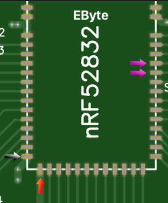
                                Downloaded the example app with three files in one folder (like the post above this one)

                                • Main file
                                • MyBoardNRF5.h
                                • MyBoardNRF5.cpp

                                In Arduino I set things up:

                                • Board: "MyBoardNRF5 NRF52832"
                                • Reset: "don't enable"
                                • Bootloader/SD: "none"
                                • Low frequency clock: "RC Oscilator" (tried others too)
                                • Port: none
                                • Programmer: ST-Link V2

                                Then I try "sketch -> upload via programmer"
                                I tried to 'wipe' the chip by clicking "tools -> burn bootloader"

                                I always get:

                                Open On-Chip Debugger 0.10.0-dev-gdc53227 (2016-04-09-13:45)
                                Licensed under GNU GPL v2
                                For bug reports, read
                                	http://openocd.org/doc/doxygen/bugs.html
                                debug_level: 2
                                0x4000
                                Info : The selected transport took over low-level target control. The results might differ compared to plain JTAG/SWD
                                adapter speed: 10000 kHz
                                Info : Unable to match requested speed 10000 kHz, using 4000 kHz
                                Info : Unable to match requested speed 10000 kHz, using 4000 kHz
                                Info : clock speed 4000 kHz
                                Info : STLINK v2 JTAG v19 API v2 SWIM v4 VID 0x0483 PID 0x3748
                                Info : using stlink api v2
                                Info : Target voltage: 3.242857
                                Info : nrf52.cpu: hardware has 0 breakpoints, 2 watchpoints
                                Error: timed out while waiting for target halted
                                TARGET: nrf52.cpu - Not halted
                                in procedure 'program' 
                                in procedure 'reset' called at file "embedded:startup.tcl", line 478
                                in procedure 'ocd_bouncer'
                                
                                embedded:startup.tcl:454: Error: ** Unable to reset target **
                                in procedure 'program' 
                                in procedure 'program_error' called at file "embedded:startup.tcl", line 479
                                at file "embedded:startup.tcl", line 454
                                the selected serial port at file "embedded:startup.tcl", line 454
                                 does not exist or your board is not connected
                                

                                I found loads of things online and in this thread.

                                • Could it be some kind of security bit that needs to be erased?
                                • I also suspect I have not connected it properly? Does the board have a power / indicator LED that should light up when its connected to power? Nothing lights up currently..
                                • Does the STLink V2 not provide enough power?
                                • I replaced the wires. Same problem.
                                1 Reply Last reply
                                0
                                • NeverDieN Offline
                                  NeverDieN Offline
                                  NeverDie
                                  Hero Member
                                  wrote on last edited by NeverDie
                                  #1516

                                  @alowhum said in nRF5 Bluetooth action!:

                                  STLink V2

                                  I can't comment on the STLink V2, but if using a JTAG, you want to power the module independently from the programmer, because the programmer is meant to sense the voltage there more than to supply it. Maybe worth a try? Looking back, I've often thought it may be the reason why my early attempts with the STlink V2 failed. At least it's something you can look into while you wait for the cavalry to come rescue you.

                                  Also, not sure as to whether running on a Mac is a good idea.

                                  1 Reply Last reply
                                  1
                                  • alowhumA Offline
                                    alowhumA Offline
                                    alowhum
                                    Plugin Developer
                                    wrote on last edited by alowhum
                                    #1517

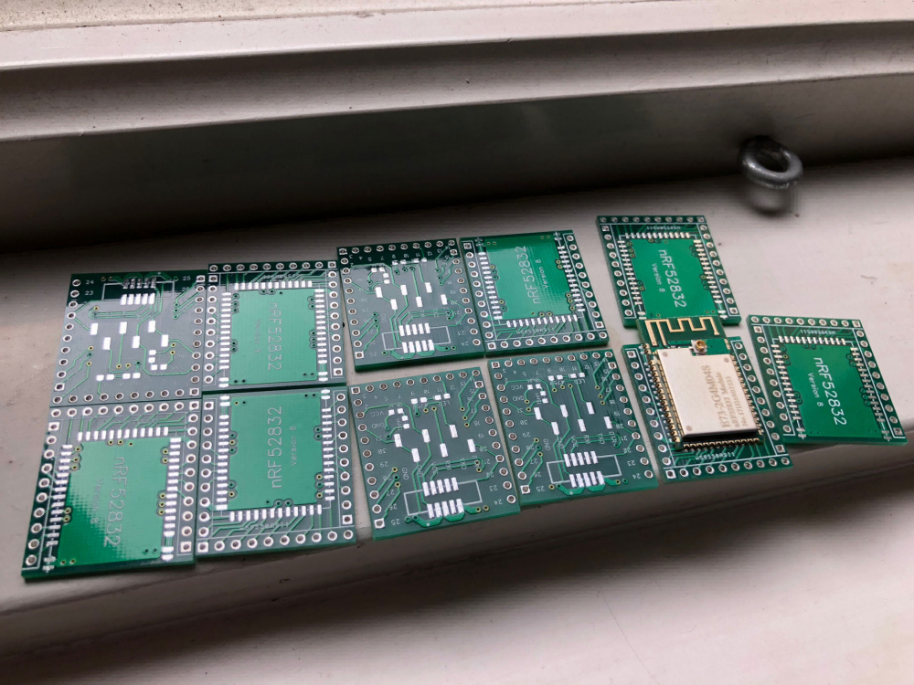
                                    W00t! Hurray! Nevermind. I just tried my other module, and that one worked fine!

                                    Open On-Chip Debugger 0.10.0-dev-gdc53227 (2016-04-09-13:45)
                                    Licensed under GNU GPL v2
                                    For bug reports, read
                                    	http://openocd.org/doc/doxygen/bugs.html
                                    debug_level: 2
                                    0x4000
                                    Info : The selected transport took over low-level target control. The results might differ compared to plain JTAG/SWD
                                    adapter speed: 10000 kHz
                                    Info : Unable to match requested speed 10000 kHz, using 4000 kHz
                                    Info : Unable to match requested speed 10000 kHz, using 4000 kHz
                                    Info : clock speed 4000 kHz
                                    Info : STLINK v2 JTAG v19 API v2 SWIM v4 VID 0x0483 PID 0x3748
                                    Info : using stlink api v2
                                    Info : Target voltage: 3.239128
                                    Info : nrf52.cpu: hardware has 6 breakpoints, 4 watchpoints
                                    nrf52.cpu: target state: halted
                                    target halted due to debug-request, current mode: Thread 
                                    xPSR: 0x01000000 pc: 0xfffffffe msp: 0xfffffffc
                                    ** Programming Started **
                                    auto erase enabled
                                    Info : nRF51822-QFN48(build code: B00) 512kB Flash
                                    Warn : using fast async flash loader. This is currently supported
                                    Warn : only with ST-Link and CMSIS-DAP. If you have issues, add
                                    Warn : "set WORKAREASIZE 0" before sourcing nrf51.cfg to disable it
                                    nrf52.cpu: target state: halted
                                    target halted due to breakpoint, current mode: Thread 
                                    xPSR: 0x61000000 pc: 0x2000001e msp: 0xfffffffc
                                    wrote 4096 bytes from file /var/folders/pg/bjymtmv12dv77vh__zxyvs600000gn/T/arduino_build_362545/MyBoardNRF5.ino.hex in 0.215516s (18.560 KiB/s)
                                    ** Programming Finished **
                                    ** Verify Started **
                                    nrf52.cpu: target state: halted
                                    target halted due to breakpoint, current mode: Thread 
                                    xPSR: 0x61000000 pc: 0x2000002e msp: 0xfffffffc
                                    verified 2768 bytes in 0.065170s (41.478 KiB/s)
                                    ** Verified OK **
                                    ** Resetting Target **
                                    shutdown command invoked
                                    

                                    I had to do "burn bootloader" once to remove the security. And then it worked!

                                    Hmm "reset enable" is still turned on. What does that do exactly?

                                    1 Reply Last reply
                                    1
                                    • NeverDieN Offline
                                      NeverDieN Offline
                                      NeverDie
                                      Hero Member
                                      wrote on last edited by NeverDie
                                      #1518

                                      Glad you found the breakout board useful. I hesitated to post it, thinking it might be too "easy," and it never did get many likes.

                                      mfalkviddM 1 Reply Last reply
                                      0
                                      • alowhumA Offline
                                        alowhumA Offline
                                        alowhum
                                        Plugin Developer
                                        wrote on last edited by
                                        #1519

                                        @neverdie: yes very useful! I was thinking I should buy some, and wanted to explore which ones could be bought without a credit card (Europe..).

                                        Perhaps you can entice some Chinese manuafacturer to put create a lot of them and then sell them on Aliexpress ;-)

                                        1 Reply Last reply
                                        0
                                        • NeverDieN NeverDie

                                          Glad you found the breakout board useful. I hesitated to post it, thinking it might be too "easy," and it never did get many likes.

                                          mfalkviddM Offline
                                          mfalkviddM Offline
                                          mfalkvidd
                                          Mod
                                          wrote on last edited by
                                          #1520

                                          @neverdie I think these are your design? Bought some when I was ordering some other stuff from Pcbway but haven't gotten around to using them yet.
                                          0_1523350311160_IMG_6984.jpg

                                          1 Reply Last reply
                                          0
                                          Reply
                                          • Reply as topic
                                          Log in to reply
                                          • Oldest to Newest
                                          • Newest to Oldest
                                          • Most Votes


                                          18

                                          Online

                                          11.7k

                                          Users

                                          11.2k

                                          Topics

                                          113.0k

                                          Posts


                                          Copyright 2019 TBD   |   Forum Guidelines   |   Privacy Policy   |   Terms of Service
                                          • Login

                                          • Don't have an account? Register

                                          • Login or register to search.
                                          • First post
                                            Last post
                                          0
                                          • OpenHardware.io
                                          • Categories
                                          • Recent
                                          • Tags
                                          • Popular