Livolo firmware mod
-
Hello! I'm trying to talk to Livolo switches (1-gang, 1-way, no RF, EU version) for both sending on/off commands AND getting on/off feedback status. I'm focusing on these versions (most Russian schematics and a lot of work in this forum refers to previous versions of the board).
- VL-C701X-2 (ver C0)
- VL-C702X-2 (ver C1)
I have my progress so far dumped at: https://github.com/jamarju/livolo-firmware
https://www.youtube.com/watch?v=t0wluQbNzUw
My goal is to minimize manipulation of the actual switch by reprogramming the original PIC16F690 with a custom firmware (see github above), and soldering 3 cables to the RF connector, which is an empty through-hole header so it's an easy enough mod.
Unfortunately the Livolo GND is actually referenced to the LIVE wire, so I had to use optocouplers to talk to an FTDI232 module safely.
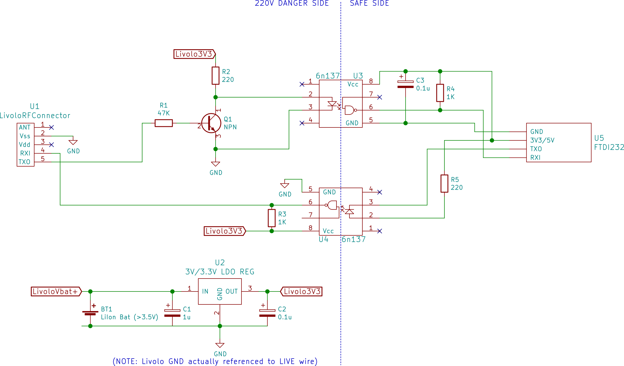
But then I found yet another problem: the optocouplers draw too much current from the Livolo power supply, which is designed to give just enough milliamps for the PIC and the blue/red LEDs, so I had to use a battery to get the extra oomph...
The final goal is to talk to an ESP8266, which I'll use to relay network commands.
Since the battery thing is an absolute no-go, I'm considering powering the ESP8266 externally, make sure the DC side floats, then hooking the PIC's TX, RX and GND directly to the ESP8266 UART, and put it somewhere hidden enough so that it doesn't kill anyone.
Is there a better way to isolate the dangerous side from the "kids friendly" side?
-
@javizzz Great work so far! I was looking at doing similar and using a RFM69 instead. I had taken a few days off next week to get stuck in. I was thinking I might use a small battery LiPo that I could charge from the AC side. Your work is a huge head start. Thanks!
Hello! It looks like you're interested in this conversation, but you don't have an account yet.
Getting fed up of having to scroll through the same posts each visit? When you register for an account, you'll always come back to exactly where you were before, and choose to be notified of new replies (either via email, or push notification). You'll also be able to save bookmarks and upvote posts to show your appreciation to other community members.
With your input, this post could be even better 💗
Register Login