What did you build today (Pictures) ?

-
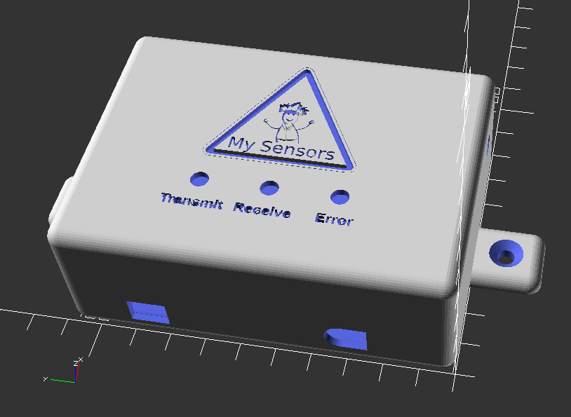
Working on setting up a new work bench in my back room in my basement where my HA equipment rack is. I wanted to build a case for my serial nRF24L01-PA-LNA gateway built on a rev8 Easy Newbie board. I just had the board sitting on a shelf on my rack, and now I want to mount it on my MDF board with all of my other equipment. Here is the design that I came up with for the case.
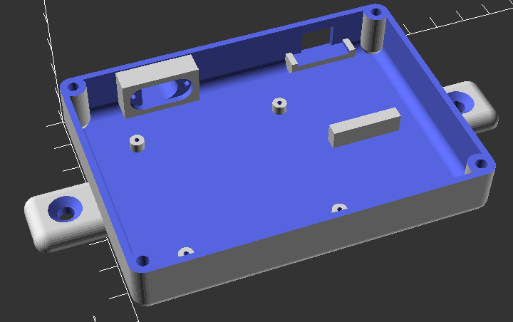
This is the inside bottom of the case:
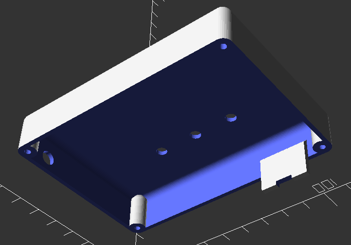
And here is inside the top of the case:
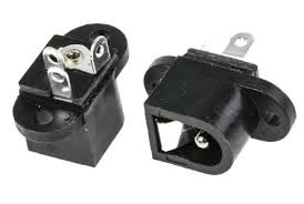
It has a spot for 3 - 5mm LEDs for the transmit, receive and error lights. There is a hole on the right side of the case for the PA-LNA antenna connector. The oval hole on the lower right side of the case is for the DC in jack. I had one of these in my parts bin:
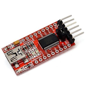
The hole on the bottom right is for the FTDI adapter connection. I am using one of these adapters that has a mini-USB connector:
I have the case running on the printer now. I will post pics when it is done.
-
For anyone interested, here is an OpenSCAD rendering of the MySensors logo:
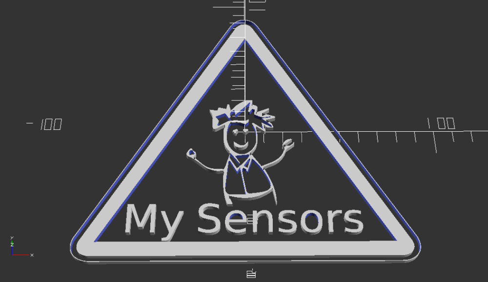
I tried posting the OpenScad code for this, but it is too long to add to a normal post. So here is a link to the OpenSCAD file.
MySensors_logo.scadSpecial thanks to @hek for giving me the .svg file that allowed me to create this. I would be curious to see peoples uses for this.
-
Working on setting up a new work bench in my back room in my basement where my HA equipment rack is. I wanted to build a case for my serial nRF24L01-PA-LNA gateway built on a rev8 Easy Newbie board. I just had the board sitting on a shelf on my rack, and now I want to mount it on my MDF board with all of my other equipment. Here is the design that I came up with for the case.
This is the inside bottom of the case:
And here is inside the top of the case:
It has a spot for 3 - 5mm LEDs for the transmit, receive and error lights. There is a hole on the right side of the case for the PA-LNA antenna connector. The oval hole on the lower right side of the case is for the DC in jack. I had one of these in my parts bin:
The hole on the bottom right is for the FTDI adapter connection. I am using one of these adapters that has a mini-USB connector:
I have the case running on the printer now. I will post pics when it is done.
So I tried printing the cover for this with my original design using Cura as my slicer, and I couldn't get the logo to print right, plus the text under the LEDs was a bit too small. I then modified the design a bit and made the logo and text a bit bigger. I again tried printing it using Cura, but the logo still was missing some lines in the body. I then thought that part of the problem was the slicer I was using, so I tried it using Slic3r and I have to say, the logo came out MUCH better.
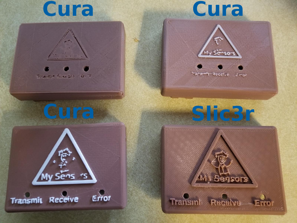
I ended up losing the Y in "My" Sensors and the ending "t" in "Transmit", but I am going to use the case the way I currently have it. Now I just have to assemble the new gateway. I am planning on making a whole new gateway and trying out the new 2.2.0 library. Hopefully my older 2.0.0 nodes will not have any issues with it, but that is why I plan on keeping my pro mini from my 2.0.0 gateway so I can revert back to that if I have to.
-
Built case for soldering tools, to easily move them out of the way.
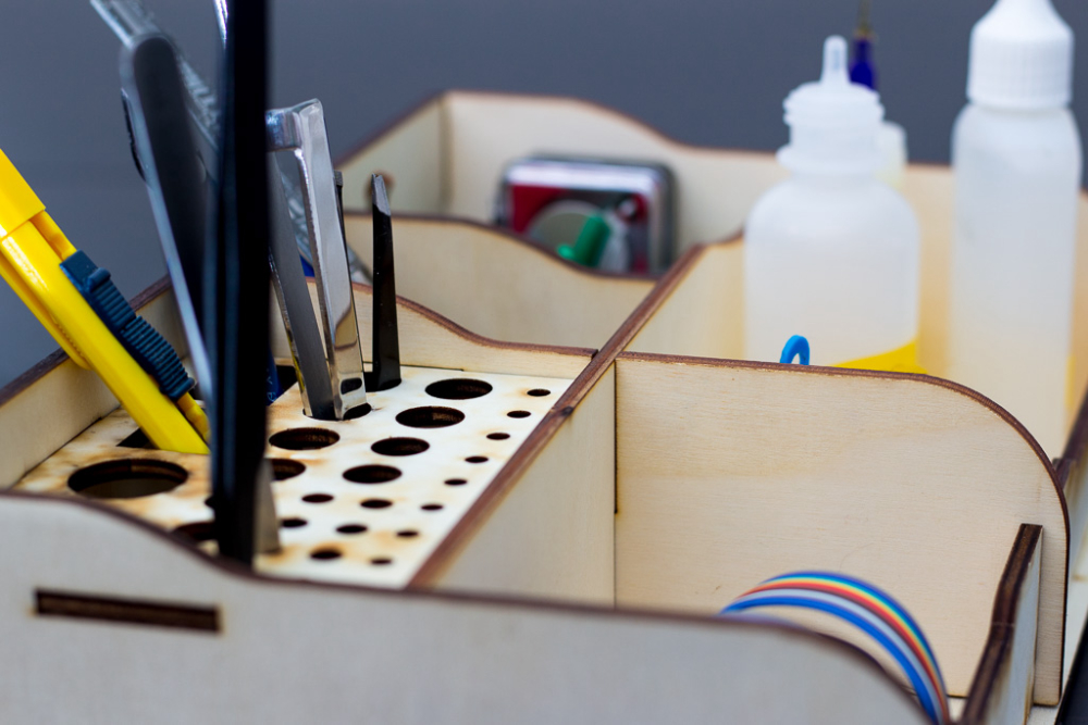
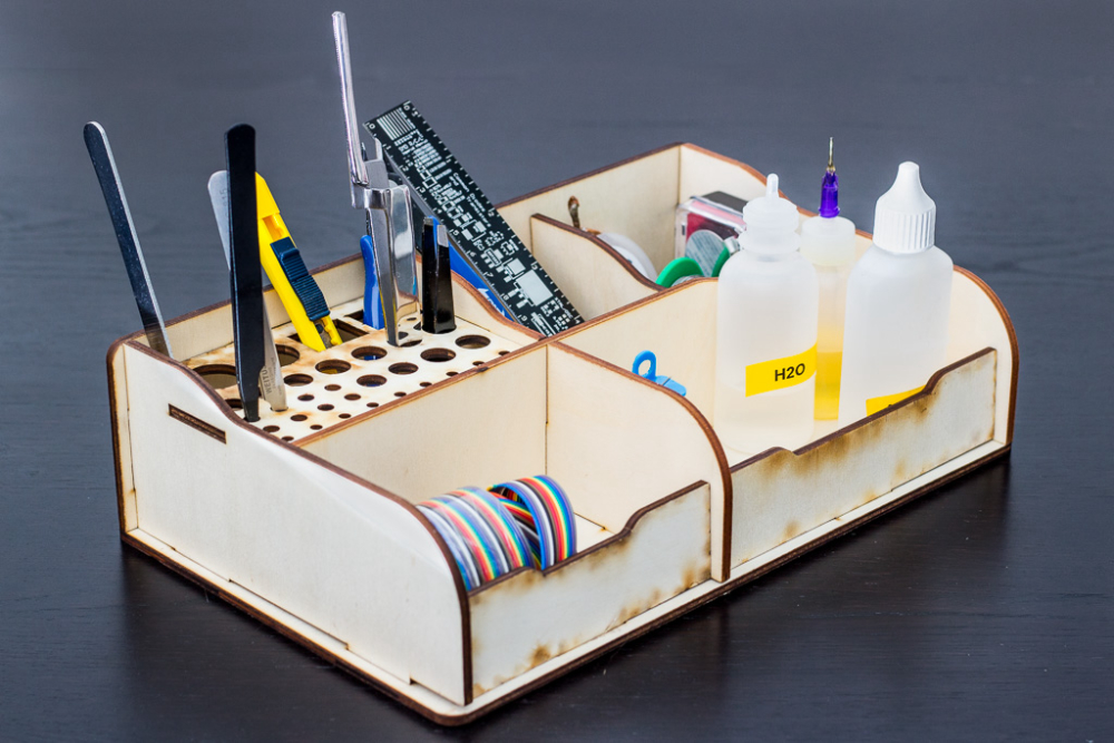
Not really, bought it on banggood and asked wife to assemble it (she likes those type of projects, especially if the office might look a tiny bit cleaner) https://www.banggood.com/DIY-Self-assemble-RC-Model-Tools-Case-Screwdriver-Box-Gripper-Package-Plier-Stand-Retro-Style-p-1257252.html?cur_warehouse=CN
Laser cut plywood(or something), looks quite nice I think. I will order few more when they appear in stock.
-
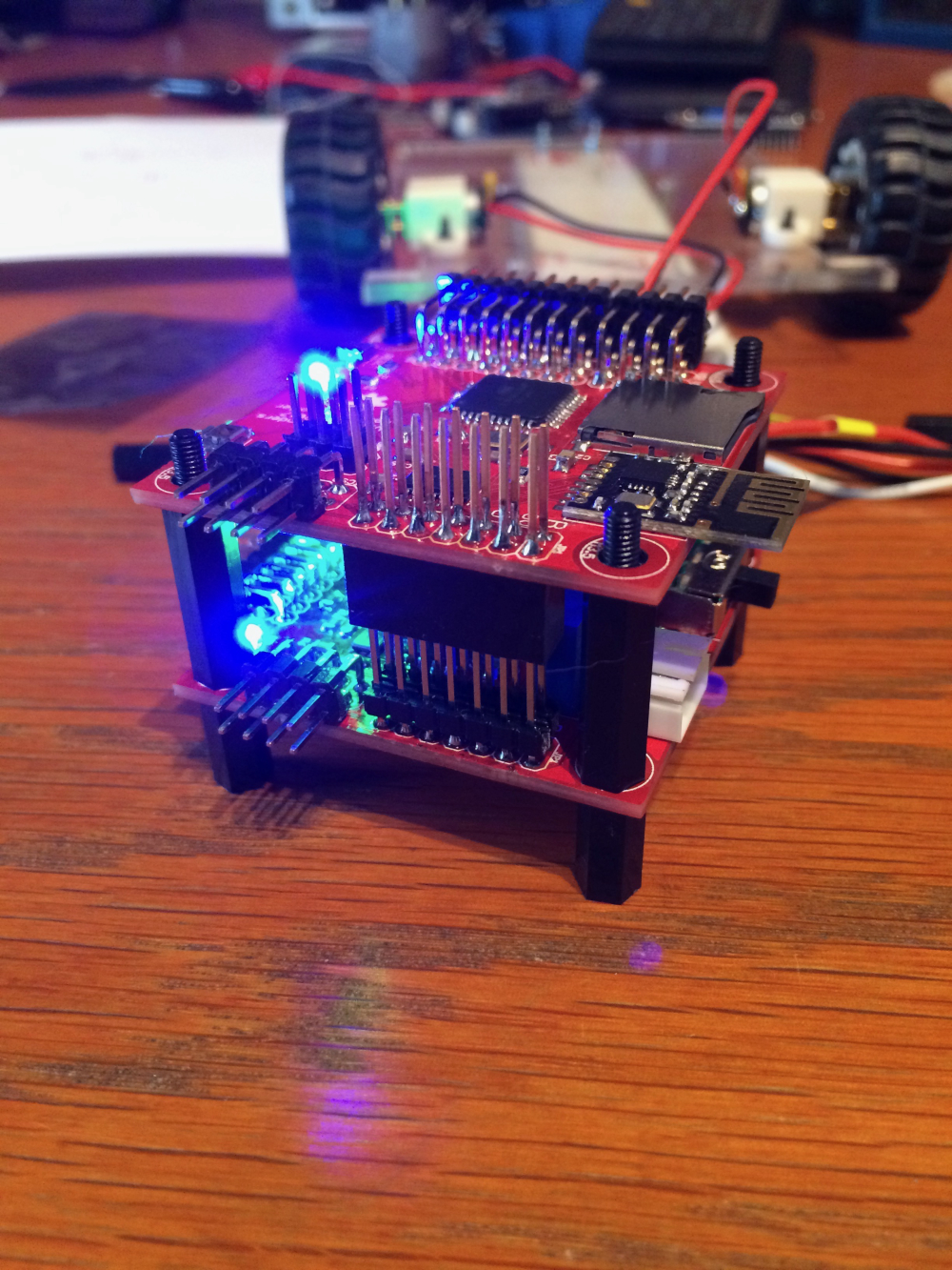
So here is my contribution to this tread: a differential drive "brain". A work in progress:
-
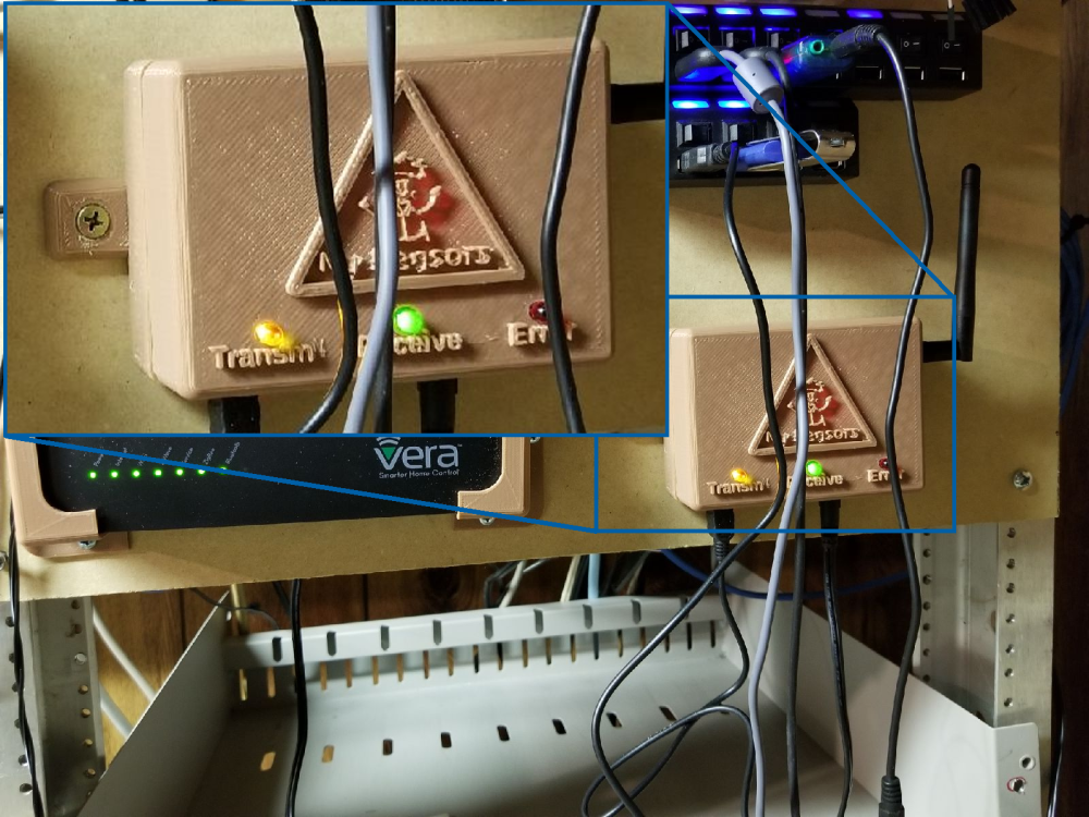
Finally finished my 2.2.0 gateway and have it mounted in the new enclosure. It appears to be talking to my 2.0.0 sensors just fine.!
-
Another motion and led strip node.
-
...and deployed.
Controller: Proxmox VM - Home Assistant
MySensors GW: Arduino Uno - W5100 Ethernet, Gw Shield Nrf24l01+ 2,4Ghz
MySensors GW: Arduino Uno - Gw Shield RFM69, 433mhz
RFLink GW - Arduino Mega + RFLink Shield, 433mhz -
...and deployed.
-
So here is my contribution to this tread: a differential drive "brain". A work in progress:
@gertsanders what is that?
-
...and deployed.
-
@sundberg84 Nice. I was wondering if I had an use for these. Now I want them everywhere!
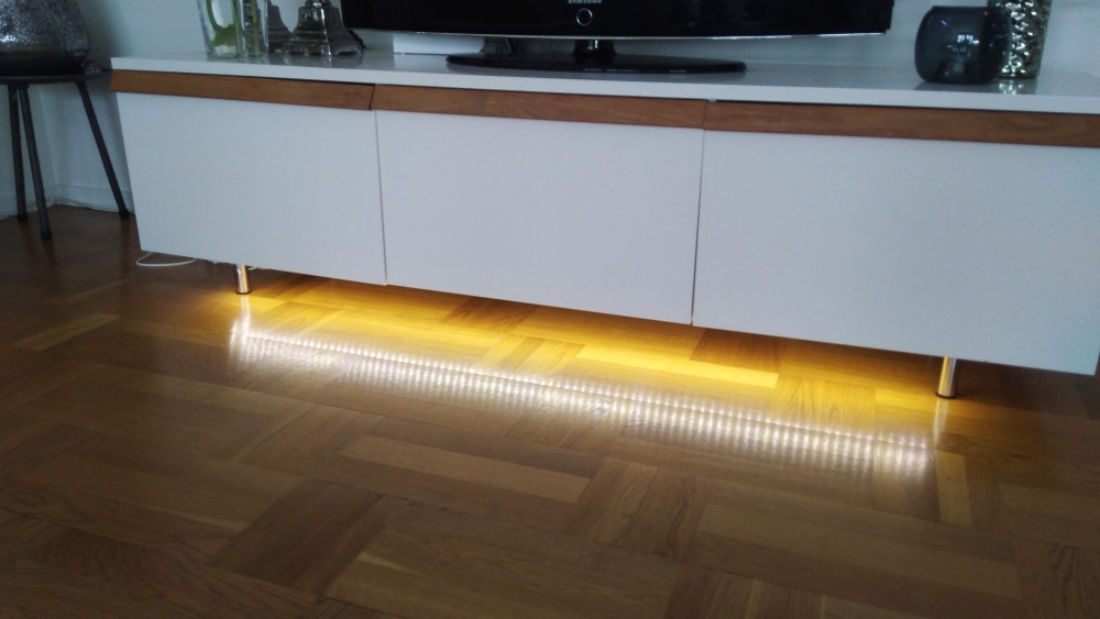
@nagelc - easy to hide, looks good and awsome as night-lights for the kids. Its also a bit woav factor connecting them to a motion detector so they lights up when someone walks by.
-
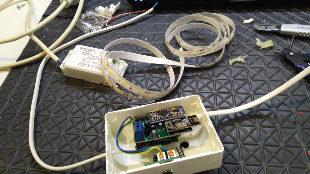
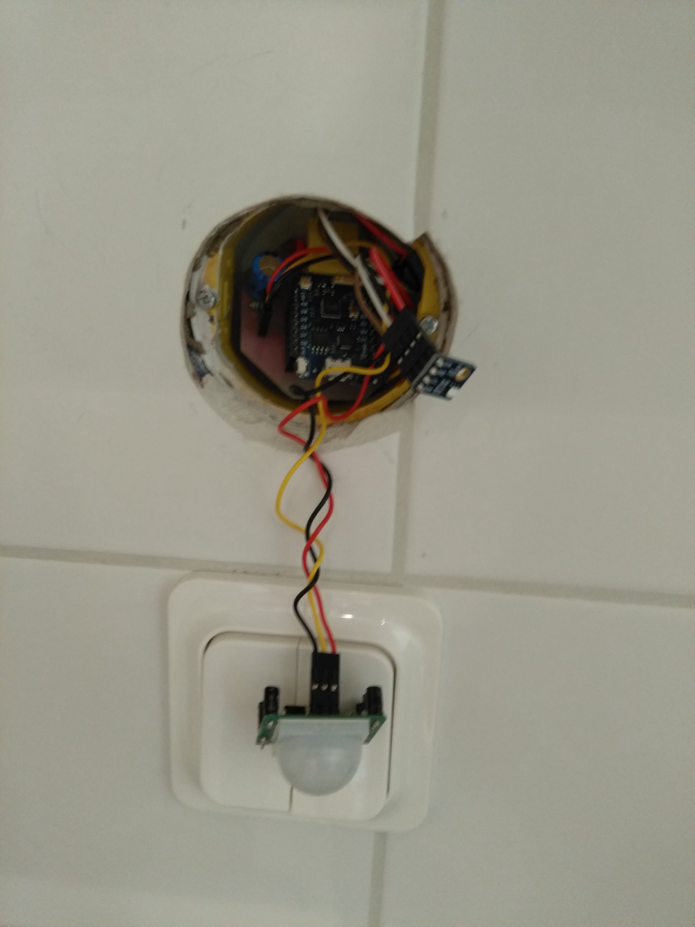
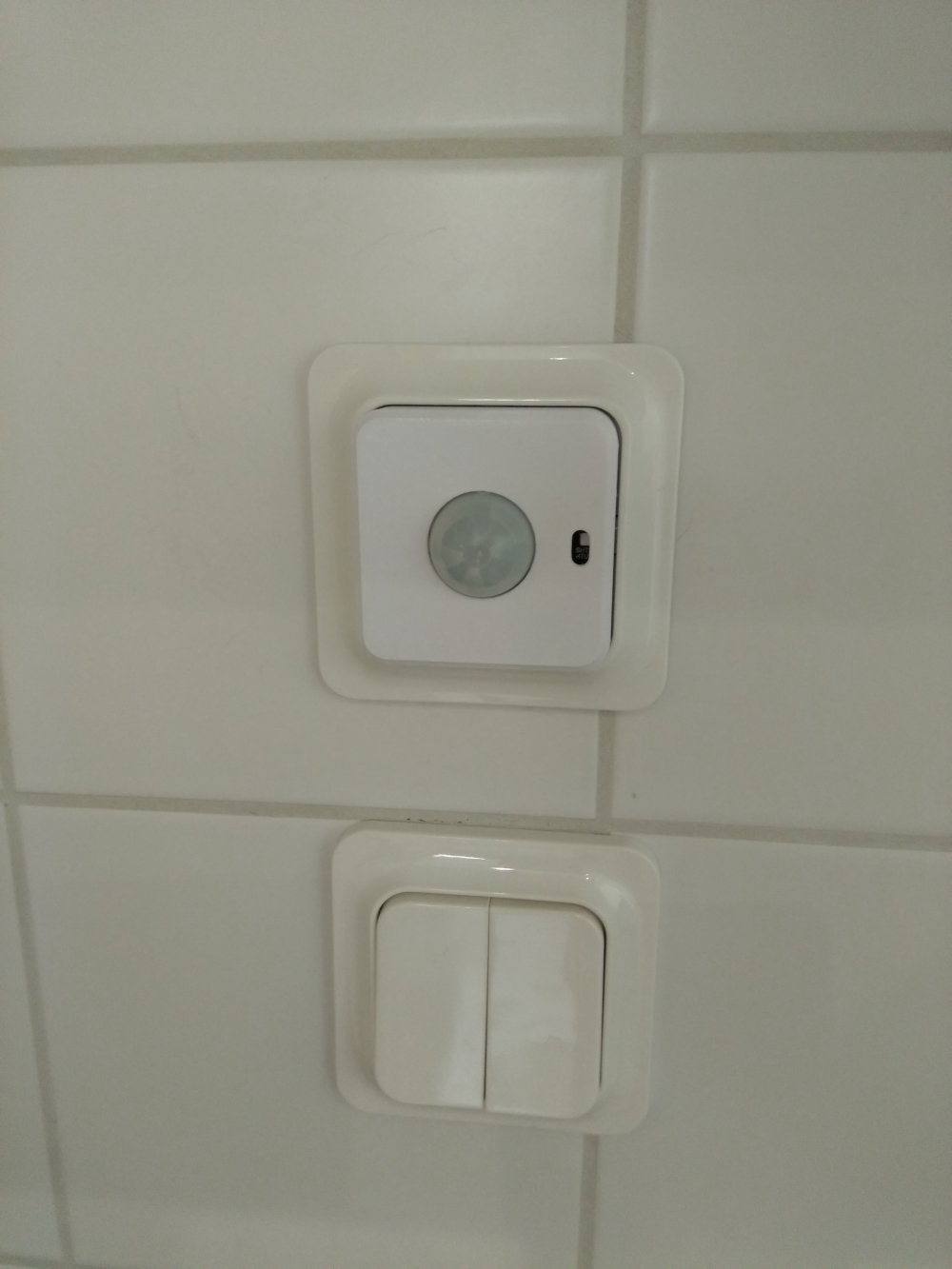
Bathroom controller. It consist of a relaybox with a HLK 5v power source, it's hidden in the closet. Then I have realy to light, nightlight, mirrorheat, and extraction fan
And then the controller it self it's a Wemos D1 Mini Pro, Si7021 Temp/Hum, sensor and a PIR HC-SR501
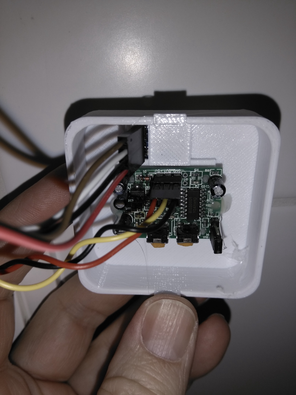
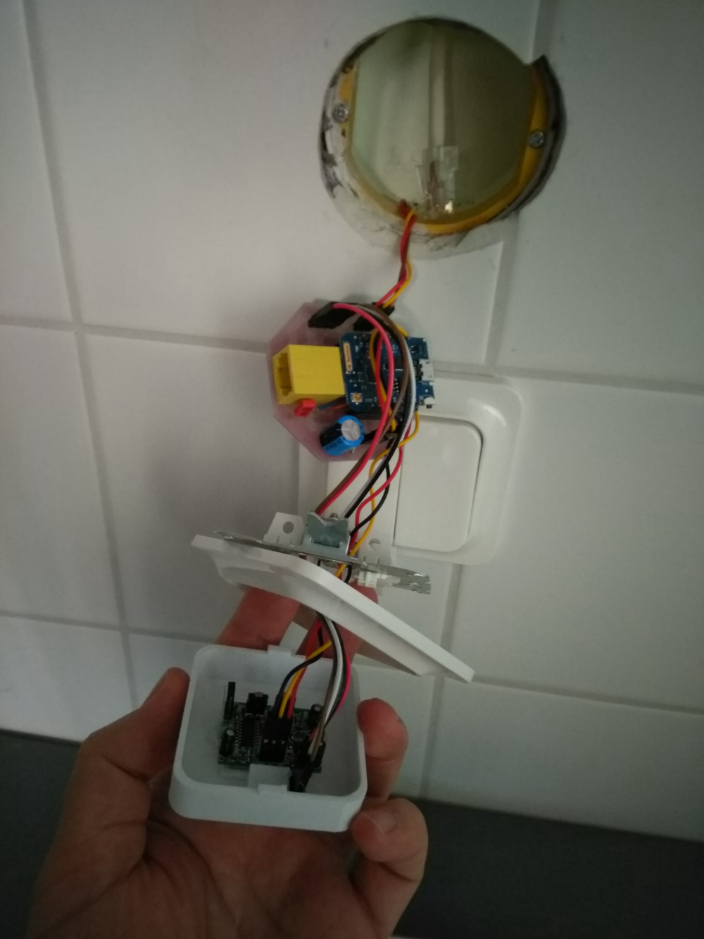
3D file is created with Freecad, STL files are available here:
https://www.thingiverse.com/thing:2890456 -
Bathroom controller. It consist of a relaybox with a HLK 5v power source, it's hidden in the closet. Then I have realy to light, nightlight, mirrorheat, and extraction fan
And then the controller it self it's a Wemos D1 Mini Pro, Si7021 Temp/Hum, sensor and a PIR HC-SR501
3D file is created with Freecad, STL files are available here:
https://www.thingiverse.com/thing:2890456@bjacobse Nice project. I like the 3D printed wall box. have you given any thought of having separate control of the lights and extraction fan? The reason I ask is that it may be beneficial to use the temp/humidity sensor to determine when the fan runs or gets shut off based on room humidity. This would be useful to reduce the chance of mold brought on by excess humidity.
-
Bathroom controller. It consist of a relaybox with a HLK 5v power source, it's hidden in the closet. Then I have realy to light, nightlight, mirrorheat, and extraction fan
And then the controller it self it's a Wemos D1 Mini Pro, Si7021 Temp/Hum, sensor and a PIR HC-SR501
3D file is created with Freecad, STL files are available here:
https://www.thingiverse.com/thing:2890456 -
@bjacobse Nice project. I like the 3D printed wall box. have you given any thought of having separate control of the lights and extraction fan? The reason I ask is that it may be beneficial to use the temp/humidity sensor to determine when the fan runs or gets shut off based on room humidity. This would be useful to reduce the chance of mold brought on by excess humidity.
@dbemowsk Thank you
For now as it's in early stage, I use the left switch to switch on (when I goto shower)on manually the fan, mirror heat, fan, and light and nightlight for 10min.
the right switch is only to start the fan for 5 min
I have not yet added humidity to start extraction fan automatically, but yes I will add this to the ESPEASY, rules -
@gohan
No, I have a fairly large electrolyte cap on power supply on the controller PCB, to stabilize the PIR/Wemod/si7021 power source.Actually when the bathroom door is open, and someone walk by the bathroom, the PIR will detect this and switch ON the light. I could consider to update 3D print to add a "wall" to block PIR.
The idea is that this PIR potentially can be used to connect to burglaralarm (but again I need to verify that I dont get false PIR reading due to sunlight) -
-
I was asking because quite some people had issues with the PIR being too close to the antenna as the antenna during transmission was inducing some noise that triggered the sensor so they needed to move them apart to solve the issue