What did you build today (Pictures) ?

-
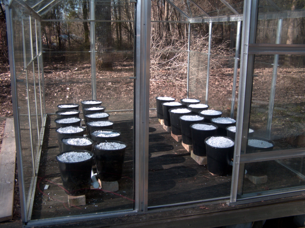
@kalina
And then once connected to the Raspy ?? What are you doing?? And a new thing for me !!@sindrome73 said in What did you build today (Pictures) ?:
@kalina
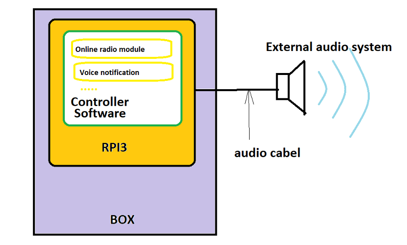
And then once connected to the Raspy ?? What are you doing?? And a new thing for me !!Maybe this picture will explain my intentions :grinning:
-
Ok, now it's clearer :+1:
-
Today's work:
- Fixed https://github.com/mysensors/MySensors/issues/1096 (PR in progress)
- Fixed 60+ spelling mistakes in the example sketches https://github.com/mfalkvidd/MySensors/commit/6e7ee6ab30d503a6f288553689fdfbe645c931e6 (will submit PR when above PR is done)
-
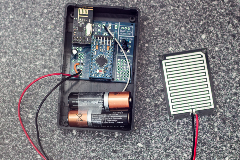
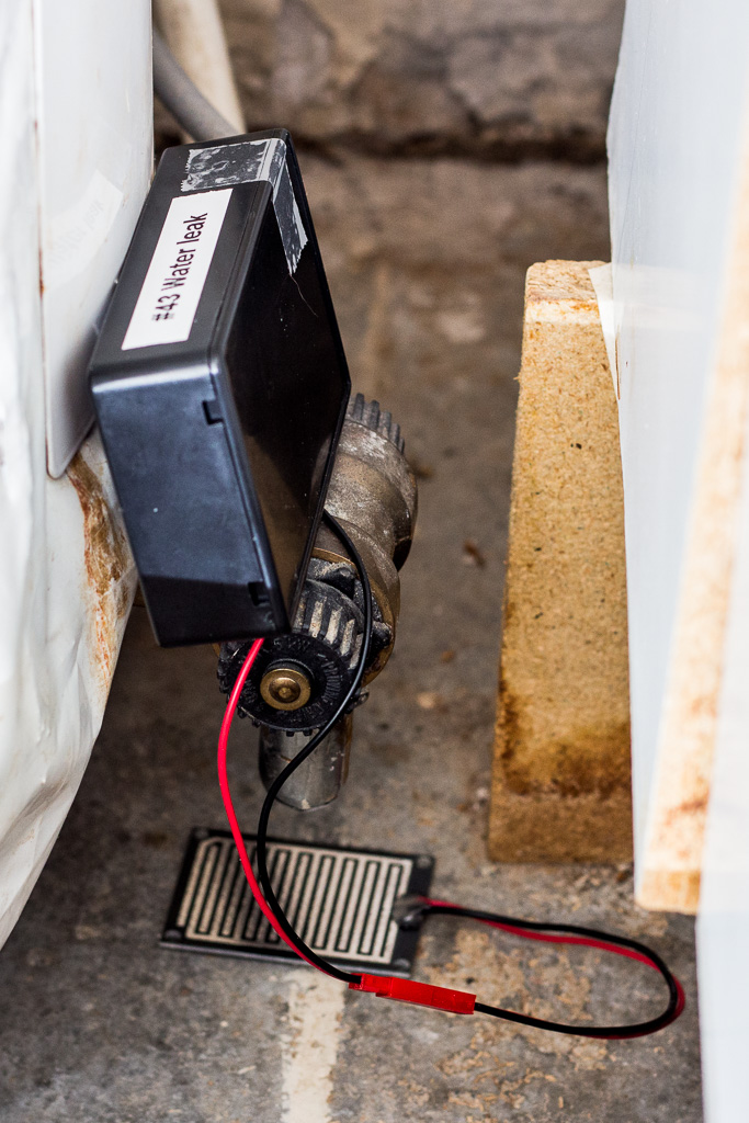
My friend had a leakage from the water heater, luckily he was around (and renting) so not much damage was made, so inspired by the incident I made another water leakage sensor for water heater (reusing the code from my previous "ribbon cable sensor" )
Then I have an "alarm" flow in node-red (via openhab) which blinks all lights in the house, sends notification to mobile phones with high priority etc. Which brings me a lot of joy when all works fine (and annoys my wife, as usual)...
They are so easy to made that I might as well make a few of them just for convenience and "feeling rich with sensors" if you guys know what I mean :)
-
My friend had a leakage from the water heater, luckily he was around (and renting) so not much damage was made, so inspired by the incident I made another water leakage sensor for water heater (reusing the code from my previous "ribbon cable sensor" )
Then I have an "alarm" flow in node-red (via openhab) which blinks all lights in the house, sends notification to mobile phones with high priority etc. Which brings me a lot of joy when all works fine (and annoys my wife, as usual)...
They are so easy to made that I might as well make a few of them just for convenience and "feeling rich with sensors" if you guys know what I mean :)
@dakipro what kind of setup do you end up with regarding bootloader / bod? What do you use to reprogram the pro minis bootloader?
-
@sundberg84 these run great on 1.8v BOD with some bootloader I found on the web (linked in the last post here ).
I use uno to flash the bootloader (tried with some IVRs but never got it to work, so just dedicated one uno prototyping hat for flashing) and then upload the sketch with IDE.
They are reporting battery from 2v to 3v (0-100%), and previous linked node is now reporting 51% of battery after 6 months, with sensor check every 2min and hearth beat every 4h.
-
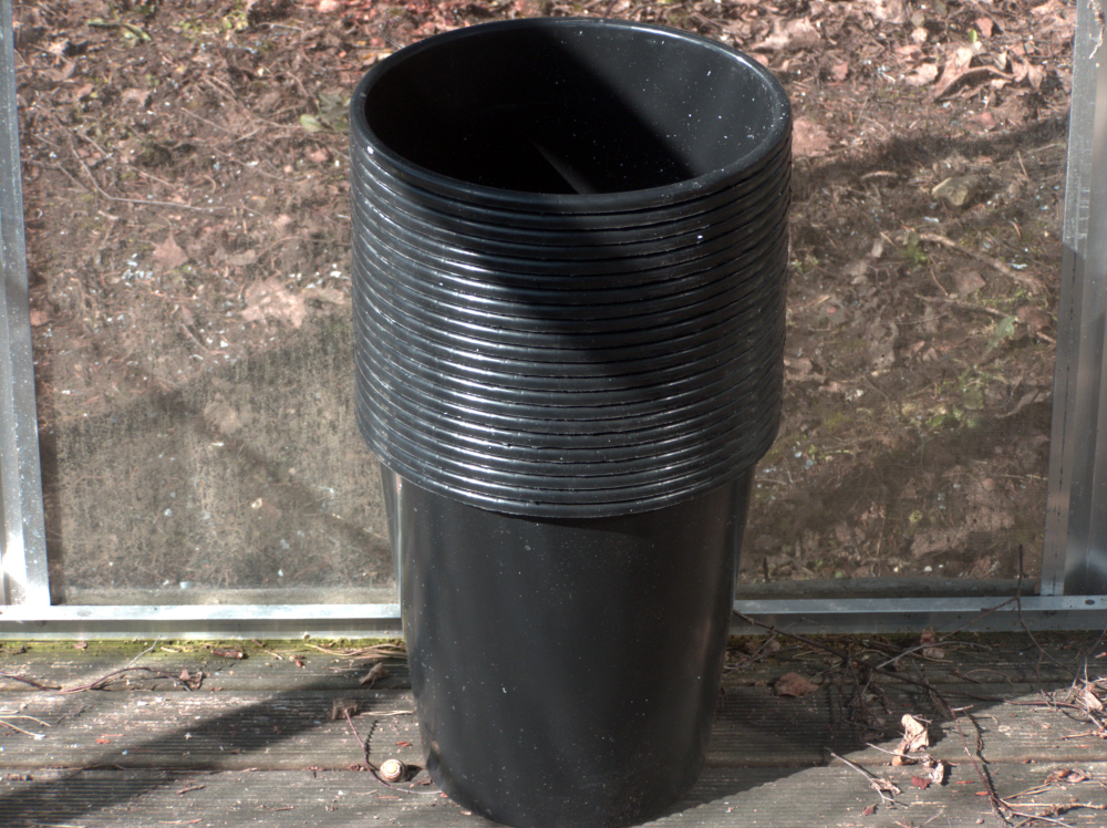
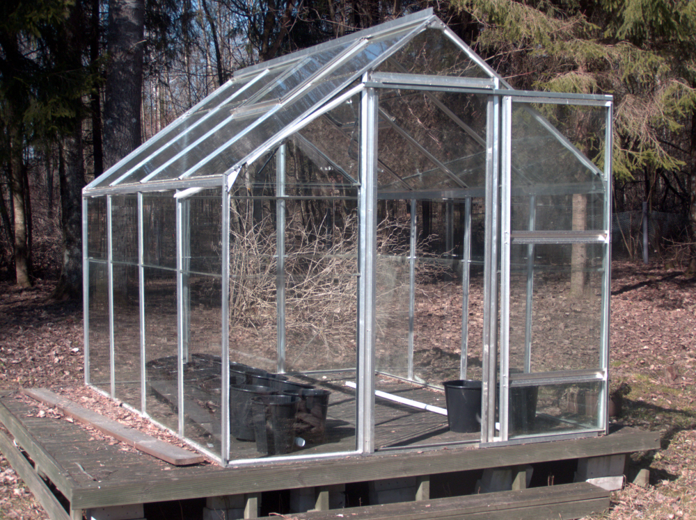
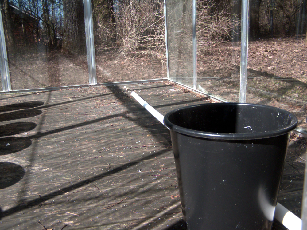
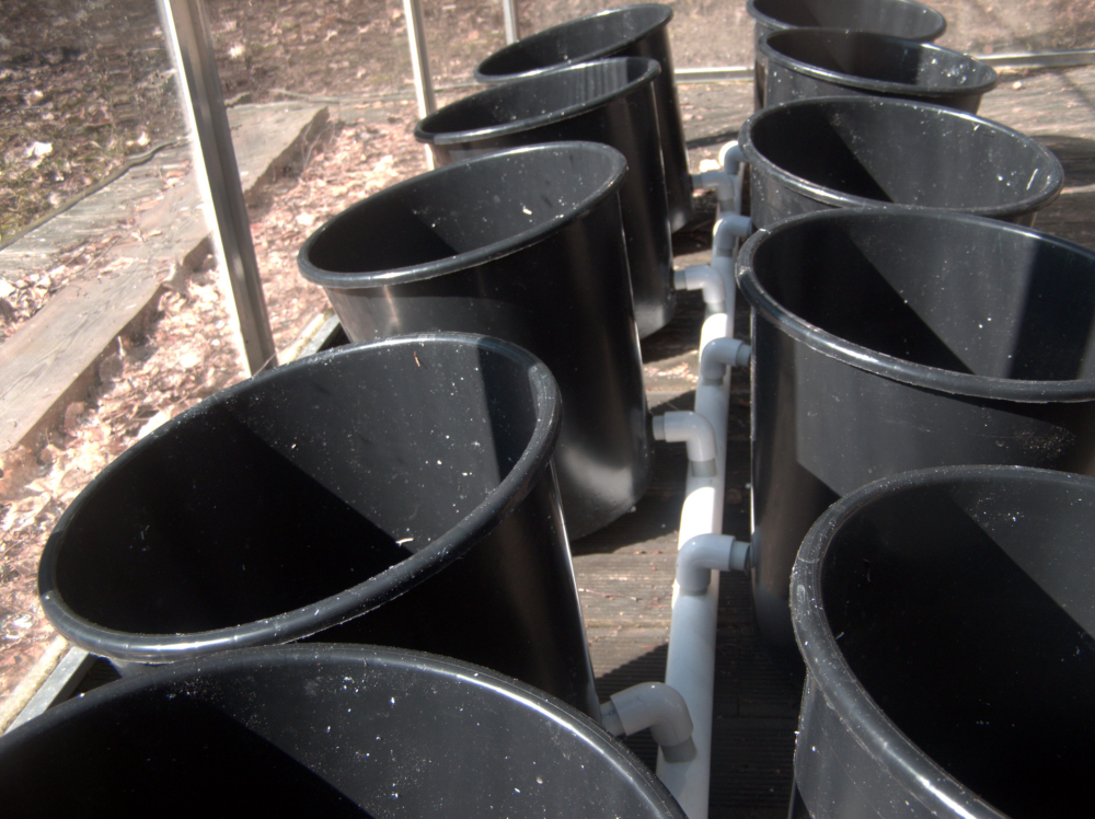
Installed z-wave roller blinds (discussed on this topic) from Swedish company m.nu .
If all is great, I will order three more motors (and two knobs/switches) for living room and terrace doors (which should also automatically keep the shades open if doors er open, to prevent damage).
Made a basic node-red flow that uses xiaomi lux sensor to get them down, but ultimate goal is to have them understand when the light is very bright and when it is "cozy", perhaps even knowing to get the blinds just low enough. Found one good explanation on the internet, will check it out (perhaps use multiple lux sensors strategically placed around the room to determine sun position and strength). Any tips and tricks?
(gif of the action, cannot upload gif to the forum https://media.giphy.com/media/5aY6vSwVn1hsdYC6nd/giphy.gif )
-
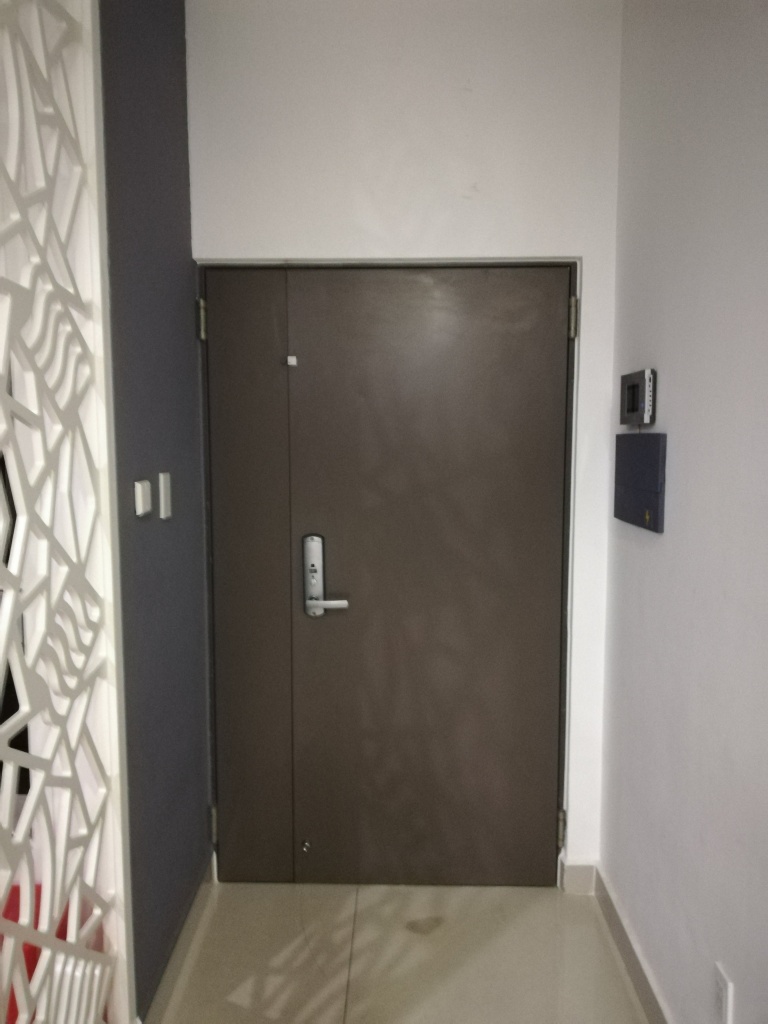
I printed a small box and put my first "22" board in action on my entrance door. So far so good it's reporting the status reliably, and looking really tiny. A big difference with my first sensor 2 years ago in a big generic project box.
Just need to clean the glue left from previous sensor now :)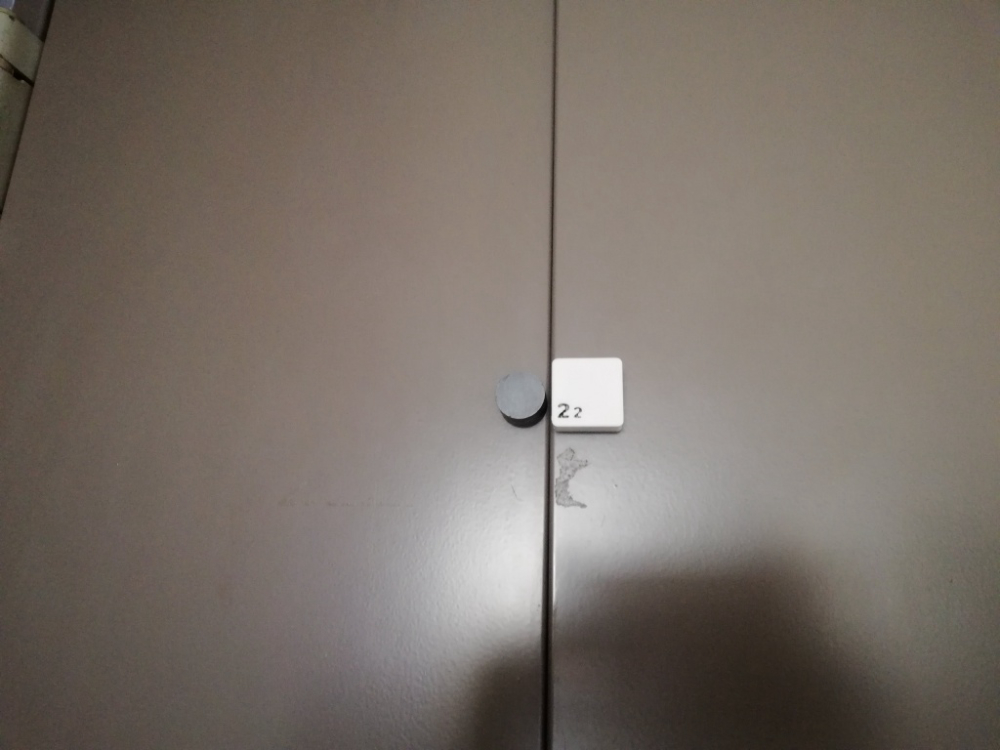
-
I printed a small box and put my first "22" board in action on my entrance door. So far so good it's reporting the status reliably, and looking really tiny. A big difference with my first sensor 2 years ago in a big generic project box.
Just need to clean the glue left from previous sensor now :) -
I've continued my quest to get all MySensors defines documented, by creating some pull requests
https://github.com/mysensors/MySensors/pull/1111
https://github.com/mysensors/MySensors/pull/1108
https://github.com/mysensors/MySensors/pull/1106
https://github.com/mysensors/MySensors/pull/1105The only keywords left new are ones that I don't understand good enough to document. These are tracked in
https://github.com/mysensors/MySensors/issues/1107 and https://github.com/mysensors/MySensors/issues/1090 -
I also added buy links for a shielded PA+LNA module and a more reliable source for regular nrf24l01+, on request by @gohan who managed to dig up good Aliexpress buying sources. Thanks gohan!
The buying links are available at https://www.mysensors.org/build/connect_radio and https://www.mysensors.org/store/radio -
@nca78 said in What did you build today (Pictures) ?:
"22" board
Looks great, can we get more info about it/link?@dakipro said in What did you build today (Pictures) ?:
Looks great, can we get more info about it/link?
Not really, I posted about it long ago here (https://forum.mysensors.org/topic/7836/what-did-you-build-today-pictures/136) It's just made for me to play by making a sensor as small as possible, but it's pretty hard to solder and with CR1632 and nrf22 the battery life won't be that good (around 1 year) so I don't think I'll publish it.
-
These arrived today...
New gateway and nodes with signing is first on my list.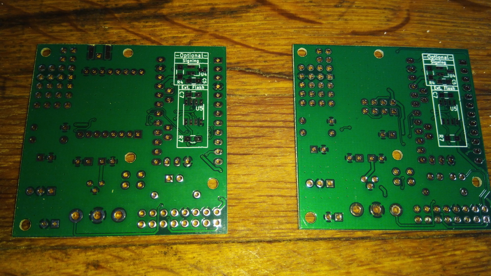
-
Working on setting up a new work bench in my back room in my basement where my HA equipment rack is. I wanted to build a case for my serial nRF24L01-PA-LNA gateway built on a rev8 Easy Newbie board. I just had the board sitting on a shelf on my rack, and now I want to mount it on my MDF board with all of my other equipment. Here is the design that I came up with for the case.
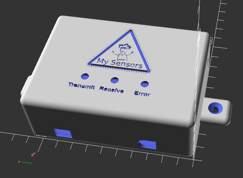
This is the inside bottom of the case:
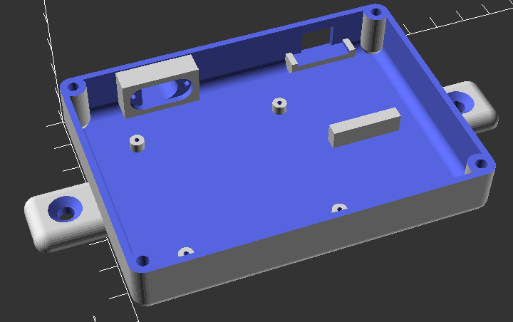
And here is inside the top of the case:
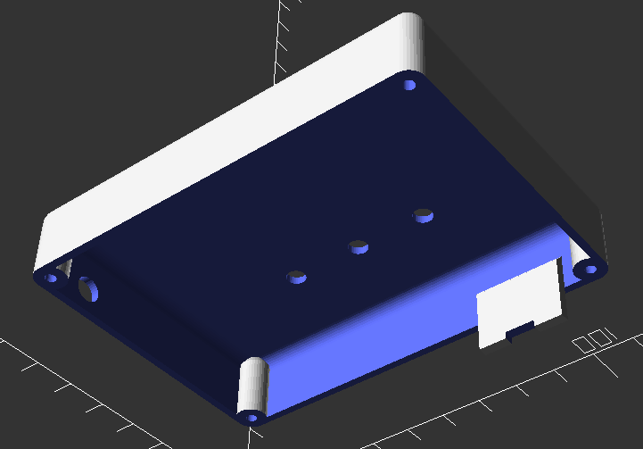
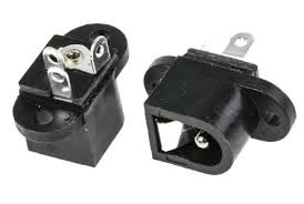
It has a spot for 3 - 5mm LEDs for the transmit, receive and error lights. There is a hole on the right side of the case for the PA-LNA antenna connector. The oval hole on the lower right side of the case is for the DC in jack. I had one of these in my parts bin:
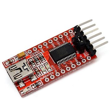
The hole on the bottom right is for the FTDI adapter connection. I am using one of these adapters that has a mini-USB connector:
I have the case running on the printer now. I will post pics when it is done.
-
Working on setting up a new work bench in my back room in my basement where my HA equipment rack is. I wanted to build a case for my serial nRF24L01-PA-LNA gateway built on a rev8 Easy Newbie board. I just had the board sitting on a shelf on my rack, and now I want to mount it on my MDF board with all of my other equipment. Here is the design that I came up with for the case.
This is the inside bottom of the case:
And here is inside the top of the case:
It has a spot for 3 - 5mm LEDs for the transmit, receive and error lights. There is a hole on the right side of the case for the PA-LNA antenna connector. The oval hole on the lower right side of the case is for the DC in jack. I had one of these in my parts bin:
The hole on the bottom right is for the FTDI adapter connection. I am using one of these adapters that has a mini-USB connector:
I have the case running on the printer now. I will post pics when it is done.
-
For anyone interested, here is an OpenSCAD rendering of the MySensors logo:
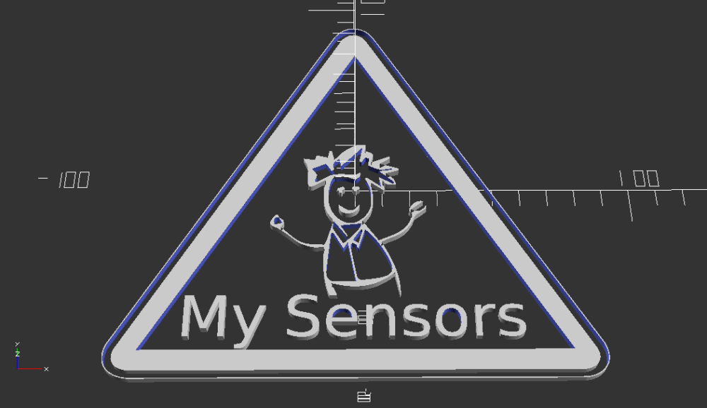
I tried posting the OpenScad code for this, but it is too long to add to a normal post. So here is a link to the OpenSCAD file.
MySensors_logo.scadSpecial thanks to @hek for giving me the .svg file that allowed me to create this. I would be curious to see peoples uses for this.
-
Working on setting up a new work bench in my back room in my basement where my HA equipment rack is. I wanted to build a case for my serial nRF24L01-PA-LNA gateway built on a rev8 Easy Newbie board. I just had the board sitting on a shelf on my rack, and now I want to mount it on my MDF board with all of my other equipment. Here is the design that I came up with for the case.
This is the inside bottom of the case:
And here is inside the top of the case:
It has a spot for 3 - 5mm LEDs for the transmit, receive and error lights. There is a hole on the right side of the case for the PA-LNA antenna connector. The oval hole on the lower right side of the case is for the DC in jack. I had one of these in my parts bin:
The hole on the bottom right is for the FTDI adapter connection. I am using one of these adapters that has a mini-USB connector:
I have the case running on the printer now. I will post pics when it is done.
So I tried printing the cover for this with my original design using Cura as my slicer, and I couldn't get the logo to print right, plus the text under the LEDs was a bit too small. I then modified the design a bit and made the logo and text a bit bigger. I again tried printing it using Cura, but the logo still was missing some lines in the body. I then thought that part of the problem was the slicer I was using, so I tried it using Slic3r and I have to say, the logo came out MUCH better.
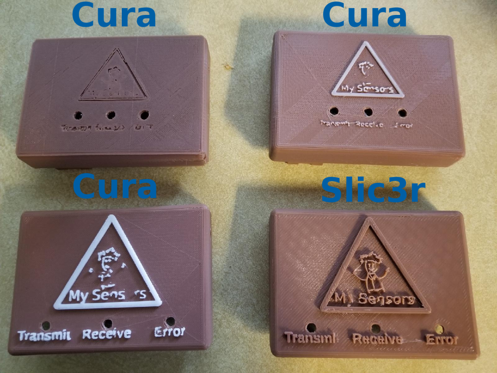
I ended up losing the Y in "My" Sensors and the ending "t" in "Transmit", but I am going to use the case the way I currently have it. Now I just have to assemble the new gateway. I am planning on making a whole new gateway and trying out the new 2.2.0 library. Hopefully my older 2.0.0 nodes will not have any issues with it, but that is why I plan on keeping my pro mini from my 2.0.0 gateway so I can revert back to that if I have to.
-
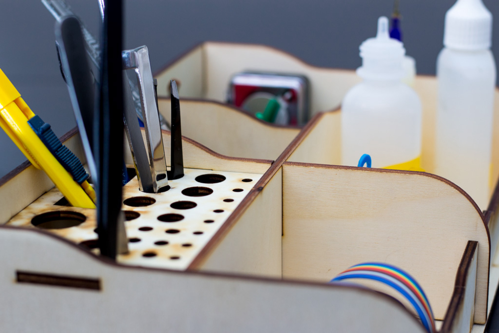
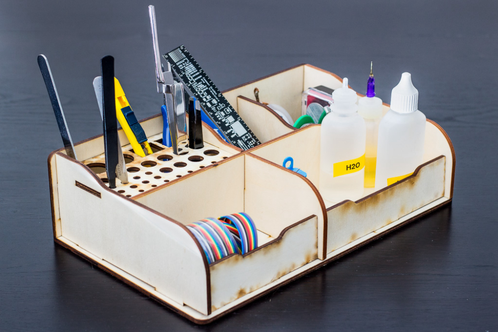
Built case for soldering tools, to easily move them out of the way.
Not really, bought it on banggood and asked wife to assemble it (she likes those type of projects, especially if the office might look a tiny bit cleaner) https://www.banggood.com/DIY-Self-assemble-RC-Model-Tools-Case-Screwdriver-Box-Gripper-Package-Plier-Stand-Retro-Style-p-1257252.html?cur_warehouse=CN
Laser cut plywood(or something), looks quite nice I think. I will order few more when they appear in stock.
-
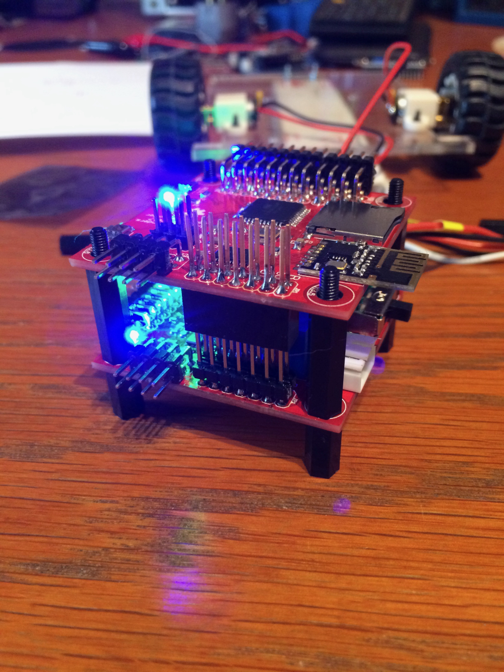
So here is my contribution to this tread: a differential drive "brain". A work in progress:
Hello! It looks like you're interested in this conversation, but you don't have an account yet.
Getting fed up of having to scroll through the same posts each visit? When you register for an account, you'll always come back to exactly where you were before, and choose to be notified of new replies (either via email, or push notification). You'll also be able to save bookmarks and upvote posts to show your appreciation to other community members.
With your input, this post could be even better 💗
Register Login